

Introduction: A Morrow Project


The Morrow Project CBR and Medkit; a collection of tricks towards creating a one-off practical prop.
Step 1: Brief

As with all good prop projects, this one started with a brief:
To re-create two props from the RPG The Morrow Project, to wit, the CBR and the Medkit. The CBR should fit within an existing ammo pouch, and both props should represent the style of 1980's period military electronics.
To make the project interesting to me, I expanded the brief in one important way; the props should have functional electronics.


Step 2: Planning


Development of the look of the props went on for several weeks. There was some indication in the game books and ancillary literature that the CBR had two lights that would light up to indicate two different classes of threat; chemical/biological, and radiological. Also, it appeared the CBR at least had some kind of curve on its body.
We were largely constrained not by what was plausible (there was an in-game excuse for practically any technology) but what could be communicated to the players. In the end, the prop had a very simplified interface capable of doing a couple of tricks but not really a good representation of what a practical device might be.
I was already familiar with period military radios and similar gear (mine detectors and so forth), so I had some idea of the kinds of shapes and details I wanted to see. The "two threat" nature led to the design of a two-level faceplate for the CBR, grouping the controls in two rough groups. In the end that, too, fell on the lack of development time to do something really interesting, the availability of hardware, and what was in reality a very small footprint to work in.
Sure, we read up on the science involved, on what were real-world plausible threats and what might be strategies to communicate that data to the operator. But this was overshadowed by the need to make something relatively intuitive and, even more importantly, appropriate in period and style.
An early discovery was a pair of Dialights; military cockpit indicator lamp housings with an adjustment to partially black out the light. More time was spent trying to find an appropriate display. I cut up little scraps of paper into scale representations of every display and other faceplate component I was considering, and played paper dolls with them for a few days.
Although I really wanted 7-segment or alpha-numeric LED displays, the small period LEDs are very hard to find these days. What I found instead was vintage Vacuum fluorescent displays.
With that, and the Dialights, I had enough to move on to the next stage of planning and development.
Step 3: Virtual Modeling


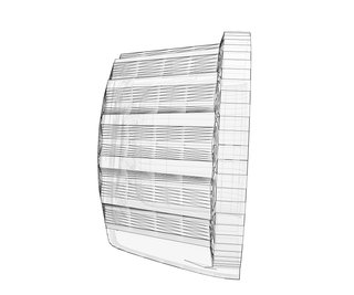
The next step was building a fairly detailed model, in scale, in my current 3d application.
Some of these parts were sent out to Shapeways to be 3d printed. The rest was built a little less detailed, as it was there to keep everything in proper scale, ensure it all fit together, and get an idea of what it would like like when completed.
I am all in favor of building complete 3d models. The one thing I wish is that I owned/was familiar with a proper CAD program, so I could work in a scaled and parametric formal that allowed easy generation of working drawings from the model.
Step 4: Physical Modeling


The faceplate to the first of the two props was printed. The body was created from scratch. Unfortunately I did not take any decent photographs during that modeling.
The body of the CBR began as a block of high-density carving foam. I rough-shaped with a Japanese wood saw, then used full sheets of sandpaper lying flat on a table to try to square it off properly.
To get the sides properly flat, I cut pieces of sheet styrene and glued them on. Then filled the gaps and rounded the corners with spackle. There was a long round of priming, sanding, more spackle, more priming, etc.
A little late in the day, I came back to cut in some extra details, such as the battery compartment door. But this build really suffers from not having enough interesting surface details. There really should have been construction seams, and more steps and other areas of interest.
Step 5: Casting


In order to be strong enough to be handled, it had to be molded and cast. In order to have any space for the electronics, it needed to be slush cast.
Unfortunately this was my first big mold, and my first attempt at a slush cast.
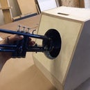
It was molded as a single-piece mold in Oomoo-30. I fixed the finished master to a board with clay, then built a small box around it with thin sheets of plywood and glue. Unfortunately the box was a little small, and worse yet, the master came free of the base piece when I poured in the silicone. I shoved it back in place, but the resulting mold was way too thin and not straight, either.
I slush-cast in Smooth-Cast, but moved the mold too vigorously at the moment the cast was settling. So instead of a smooth shell of plastic, I got a crazy, twisty, heavy mass of plastic. It took a couple of days with a Dremel to try to open up the clogged interior enough to be able to stuff the electronics in.
Step 6: The Second Housing


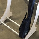
The Medkit also needed a box. The inspiration came to fit it to the existing pouch used to carry the old Army First-Aid kit. And that made it only logical to take apart one of the plastic First-Aid kit boxes and modify it for the housing.
Basically, I hacked off the top, then cut a rectangle out of the outer corner. I replaced the latter with a curved piece of styrene, and the former was filled with a roughly-shaped block of balsa wood.
Then lots of sanding, lots of Bondo. The flexible plastic of the original box insisted on flexing, popping free anything I glued to it, and balling up when I attempted to sand or file it, and basically I would have saved time by starting from scratch.
Especially when it came time to cut details like the battery compartment door. Not even my new panel line tool (bought at the model department of Ace Hardware) could make this a calming experience.
Step 7: Tricorder


The "inspiration" for the top of the Medkit was the Medical Tricorder from TOS. Basically, a raised screen with 5x7 proportions, and three buttons or other controls. The in-game nature of this prop -- what it was supposed to do -- was basically impossible to try to make into any realistic set of controls, so unlike the CBR, this is just three arbitrary buttons and a display that reads "something."
The basic shape was made from several thicknesses of balsa wood. The details of the "hood" and the smooth inside radius of the curve were built up with Apoxie Sculpt. And as usual, there were multiple rounds of Filler Primer, sanding, spot putty, more primer, etc.
In the end this, too, would have looked better 3d printed. Especially since -- well after this project -- I more thoroughly explored the much cheaper "White Soft Flexible" material at Shapeways.
Step 8: Test Fit


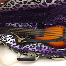
Always a sanity check; both models are placed together to see if they seem to be roughly in scale with each other and belong in the same universe.
And, no, they didn't. The Medkit sucks. But it is done, and for this project it is close enough. The CBR is the star of this particular build, and the reason for that will soon become apparent.
Step 9: Clean-Up


The masters were cleaned, and painted with a gloss coat, and prepped for molding.
For the Medkit lid I experimented with a two-piece mold; I molded the outside faces, then carefully hand-rolled strips of clay to get a uniform thickness and packed those inside. Then I added the top piece of silicone. The theory may have been sound, but the execution suffered; the resulting cast was much thicker than intended.
The Medkit body was another one-piece mold; simply poured open from the top. I think box molds are a better solution even for open-ended structures like this. At least the slush cast was much more successful. By pouring only a cup of Smooth-Cast at a time I was able to let it coat two surfaces at a time to fairly uniform depth.
Alas, I'd added some detail to the battery compartment just before molding, and I had to go back and add that same detail to the finished cast on the CBR. I also had some ideas about how to achieve incised letters, but hadn't worked out the details. So instead I carved into the finished cast to make hand-formed letters. Which all leads to a somewhat amateurish look to the props.
Step 10: Glowy Things


The Dialights were easy to work with.
I stripped out the original lamp base, pre-wired a high-intensity LED with ballast resistor, and glued it inside the indicator bezel with hot glue.
Step 11: Fancy Glowing Things


The heart of the CBR is the VFD -- Vacuum Fluorescent Display. These are a high-voltage, cold-anode display that glows a cool blue-green. They had their highlight in POS registers and VCRs in the 80's, and automobile dashes up through the early 90s. The one I used was old Soviet stock (or perhaps a modern remake -- in any case, found on eBay and shipped from the former Union).
It is relatively easy to make a light in them. You need a trickle of current across the heater; I found a limiting resistor through trial-and-error for this. And then you need from 9 to 70 volts to drive the anode and grid.
The display is of course multiplexed. If you tie a bunch of the leads together, you can make a static display of the same number repeated as many times as you like, and that will drive off a single 9V battery. That's what I did for the Medkit. It displays "0000" when the appropriate button is pressed. (It also had a cheap greeting-card type sound chip in it that played a sample of, of al things, a SCUBA diver. Played out the tiny speaker, buried inside the plastic case, it sounded appropriately medical-technology-ish.)
To really play with the display, though, requires a little more machine intelligence...
Step 12: Minimal Arduino


The VFD for the CBR is driven from a Supertex HV5812; it is basically a high-voltage latching shift register. I found mine at Mouser electronics. But to handle that chip, plus the two Dialights, and the selector knob, and two more lights, and sounds, and so forth, I needed a little more computing power.
These days I'd probably spend on an Arduino micro or nano or one of the similar off-shoots. For this project, with the very limited space I had for the circuit board anyhow, I built a minimum-parts Arduino compatible on perf board and soldered the other components around it.
Since I own an Adafruit "tinyISP" programmer, all I needed was the standard 6-pin header and I could program via the Arduino IDE. Which is a bit simpler than wading through raw C for the AVR (which I've done in the past).
Step 13: Bells and Whistles


For controls, the CBR uses a miniature multi-position rotary switch, and a single button. Because I was already pushing the available pins on the Arduino, the rotary switch is wired into a resistor ladder and sent to an analog pin.
In addition, there is a capacitance sensor wired to the "antidote injector port" on the bottom curve of the housing. This uses two Arduino pins and gives it the ability to sense flesh contact with the sensor.
Finally, using the Tone library for the Arduino, I was able to create two different siren noises, and a Geiger-counter-like clicking sound. Plus a couple of chirps for one of the test modes. These tones were amplified just slightly by running them through a power darlington that switched the full power of the 9v battery.
All of the components were dressed on the bench with wire harnesses using scraps of ribbon cable, then everything was led back to the circuit board. The whole mess was hot-glued to the faceplate, so it was just barely possible to open and close the case to swap batteries...or continue programming.
Step 14: The Circuit

The circuit below isn't too silly, but it is complicated enough to try to put on perf if I ever did another of these things, I'd have a PCB printed for it.
There are also at least two things I'd change. One is to use an LM386 or similar as a speaker amplifier. The other, and more important, would be to use a custom-made boost power converter instead of the 24v DC-DC. You can build one with as little as a fast switching diode and an inductor -- especially if you use the microcomputer itself as the pulse generator.
Step 15: Pergramin...porgammin...pregram...CODING

The actual code is also incredibly messy stuff.
The main issue is that I was trying to simulate analog-era electronics. There are all sorts of sequences where it wants to fade up a light, or flash twice then pause, or so something else that requires elaborate timing.
And multiple "delay()" calls won't do it. Especially since the VFD needs to be continually refreshed in order to actually display words and numbers. (Plus, there is a level of interaction -- the user needs to be able to hit buttons or switches at any time -- that precludes the software sitting in a closed loop or delay() for multiple clock cycles).
The answer is a primitive sort of RTOS -- Real Time Operating System. In essentials, I had counters running constantly in the background, thus was able to cycle through the entire main() loop continuously. Events would take place when various counter values were reached, and flags were tripped.
As it is presented to the user, the CBR has five settings;
OFF
Test Mode
ON
ON (silent alarm)
Treat
In the "Treat" setting, the capacitance sensor was active. If the user brushed the treatment port (actually, a blue LED in a nifty chromed bezel I found at AllElectronics) a vibration motor would run briefly, the light would flash, and the display would change to read the number of doses left before refill would be necessary.
In the "Test" setting, pressing the all-purpose button would flash all the lights twice while playing a short "chirp." If the user left it in "Test" for about fifteen seconds, it would automatically enter what was displayed as "Self Test." It would display various random-generated numbers with cryptic alpha prefixes, and then conclude in about two minutes by flashing "Test Good."
(Or, rather, by displaying something like "7E57 g00d" -- this was a seven-segment display, after all!)
Step 16: Final Detailing


The entire thing is primed, painted in olive drab, then washed with acrylics to bring out the detail. It probably would have been smart to hit it with a couple of coats of gloss-coat to seal it before the acrylic stage, however. It looks more plastic than it should, and feels slightly oily to the touch.
A few last little details finish it up. Such as the dataplates; these were printed on water-slide decal paper, slipped onto tiny bits of trimmed sheet metal, then glued down and sprayed over. Again, if I had looked further forward, I would have designed in an inset dataplate space in the castings, and these would have looked nicer.
The final knobs arrived from the 3d printer. I shined them up, and hacked up a couple of cheap knobs for the brass insert, which got epoxied inside the new ones. The print had been designed for white plastic inserts, but in the end white paint was used instead. Oh; and the letters on the Medkit were done with small styrene letters (used by model railroad builders) but the lettering on the CBR faceplate is part of the 3d print.


