

Introduction: A Simple 3D Printed Robot


Allow me to date myself. I grew up with erector sets and then LEGO. Later in life, I used 8020 to build prototypes types of systems I designed. There were usually scrap pieces around the house that my children used as their version of an erector set. The greatest thing about both of those building systems was that they were highly reusable. By breaking apart bricks or unscrewing some bolts, you could be off building somthing new in a couple of minutes.
When my children started to build robot kits, I noticed somthing sad, our robot graveyard was getting larger by the year. The kids would build a kit, learn the lession and be done with the robot. They would occasionally scavenge the graveyard for parts, but for the most part the bulks of the kits just sat. It became obvious that the kits were good at teaching a single task, but you could not easily break the kit down and reconfigure it to a new or different task.
There a a lot of simple robot designs out there. This one is mostly 3D printed and used a raspberry pi.
The idea is to produce a rapid prototype of a robot.
Supplies
An 8020 Series 10 bumper for the Raspberry Pi 4 with a proto board
http://www.thingiverse.com/thing:3744587
Prototype Smooth Beams Large Holes http://www.thingiverse.com/thing:3589546
TT Motor mount for 8020 Series 10 extrusions http://www.thingiverse.com/thing:3752572
Adafruit CRICKIT HAT for Raspberry Pi
https://www.adafruit.com/product/3957
DC Gearbox Motor - "TT Motor"
https://www.adafruit.com/product/3777
Orange and Clear TT Motor Wheel for TT DC Gearbox Motor
Step 1: The Design


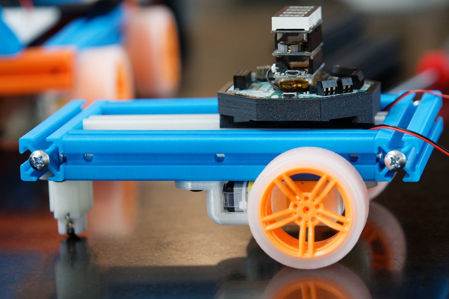
The basic design presented is for a differential wheeled robot. (https://en.wikipedia.org/wiki/Differential_wheeled...) It incorporates two drive wheels, one on each side of the robot.
The basic design presented is comprised of a platform made from 5 printed beams (2x 4in, 3x 5in), two covers for TT geared motors and a printed stand for a castor. You will also want to print a holder for the microcontroller of your choice.
The example presented is built around Adafruits Crickit, but any Arduino, Feather, or Raspberry Pi that supports a motor driver board can be used.
Step 2: Hardware Needed Outside of Printed Parts
Some type of micro controller with Motor control
This is the heart of the project. There are many different choices available.
Machine Screws 1/4-20 x 1/2
Available at your local hardware store
T-Nuts and screws
1/4-20 Slide-in Economy T-Nut - Centered Thread 0.21 https://8020.net/shop/3382.html
1/4-20 x .500" Flanged Button Head Socket Cap Screw (FBHSCS) 0.30 https://8020.net/3342.html https://8020.net/3342.html https://www.amazon.com/80-20-Inc-Assembly-Slide/d...
Two TT Gear Motors
https://www.adafruit.com/product/3777
https://www.servocity.com/right-angle-gearmotor
Two Wheels
Adafruit Orange wheel : https://www.adafruit.com/product/3766
Actobotics 2.55" Press Fit Wheel: https://www.servocity.com/2-55-press-fit-wheels
Actobotics 3.10" Press Fit Wheel: https://www.servocity.com/3-10-press-fit-wheels
A ball castor
https://www.adafruit.com/product/3949
A battery case or system
4 x AA Battery Packs for NiMH ONLY
https://www.adafruit.com/product/3788
3 x AA Battery Packs for Alkaline ONLY
https://www.adafruit.com/product/3842
For higher current projects I tipicaly use a Battery Elimination Circuit (BEC) from a Radio control vendor. This is beond the scope of this project and if there is intrist can be covered in a seperate insturctable.
Some type of micro controller
Step 3: Print the Parts


The files can be found on Thingaverse
The simplest design will require:
https://www.thingiverse.com/thing:3589546
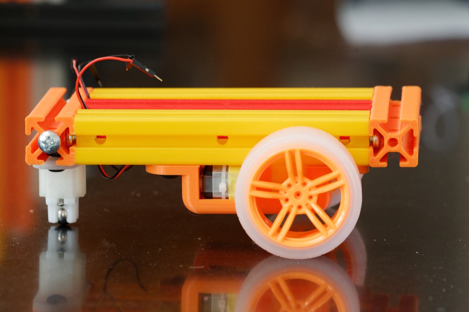
Three long beams - for this example 6in printed in yellow and red
Two short beams - for this example 4in printed in orange
Two motor covers https://www.thingiverse.com/thing:3752572
One castor mount https://www.thingiverse.com/thing:3801804
One controller housing
If you are using a Feather or a Circuit based cricket, then
https://www.thingiverse.com/thing:3763330
If you are using a Raspberry pi based cricket, then
Step 4: Assemble the TT Motors and Wheels


Opening
- Insert the screws into the holes on the printed motor bracket.
- Place a t-nut on the end of each screw
- Insert the motor into the bracket. The top of the moter has a plastic rectangular tab. The bottom of the motor may have a shaft that extends beyond the end of the motor case.The bracket has a rectangular slot at the top, and a V-shaped slot at the bottom.
- Attach the wheel of your choice to the shaft on the side of the motor. (This step may be done after you have mounted the TT motor and cover to the beam in the next step).
Step 5: Assemble the Frame


Intro
- Place a 1/4-20 x 1/2in screw in each end of the long beam.
- Slide the ends of the screws in the three long beams into a channel on the short beam.
- Lay the assembly flat on a table. Spread the three long beams out so that the head of screw on each of the long beams is visible in a hole on the short beam. Tighen the screws.
- Slide the TT motor and covers on to the outside beams.
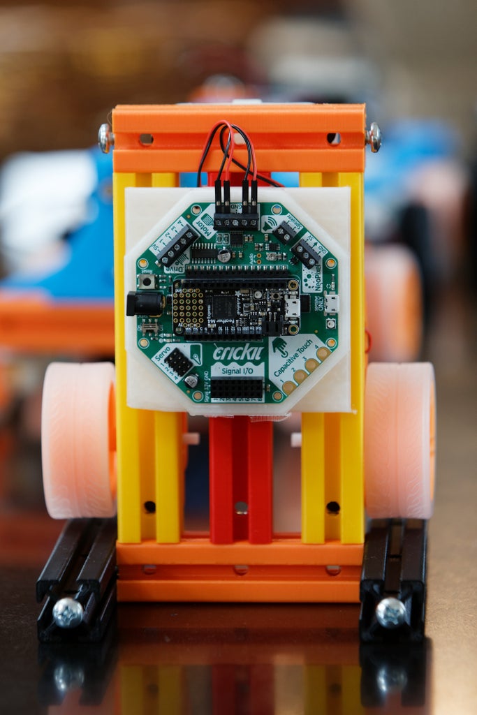
Step 6: Mount the Controller and Battery Pack


Step 7: Tips and Tricks 1 - the Test Stand


One of the nice thing about a scratch built project is it is quick and easy to modify. A great modification while you test code is a way of positioning your robot so that it does not run around on your desk. By printing two additional beams (6in is the case of the example) you can make a stand for the robot.
Step 8: Load Some Test Code and Test It Out
Step 9: Tips and Tricks 2 - Wire Routing


If you are careful it is possible to route the wires from the motor under the wire nut.
Step 10: Tips and Tricks 3 - Wheel Alignment


The pictures above can be followed to make the adjusts the wheel alignment.
Step 11: You Are Done and Some Ideas for the Future


There are a lot of ways that the project can modified. It can be easly turned into a larger, faster, robot by printing some longer beams and adding more motors. There are a number of 8020 series 10 sensor holders available. Servos can be added. Or the whole idea af a robot can be scraped and the project can be turned into a paper airplane launcher. You get the idea.


![Tim's Mechanical Spider Leg [LU9685-20CU]](https://content.instructables.com/FFB/5R4I/LVKZ6G6R/FFB5R4ILVKZ6G6R.png?auto=webp&crop=1.2%3A1&frame=1&width=306)


