

Introduction: Analog Output


Now that you have finished the Hi-5 Collector and put a digital input and output to use, it is time to expand on your Arduino knowledge and learn the basics of an analog signal.
Analog output pins on your LilyPad USB make it so you can control devices with a varying output value. For example, instead of turning an LED on/off, you can fade it on and off or turn it on at a specific level of brightness.
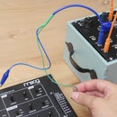
In this lesson, you will work with a sewable LED circuit and be introduced to a new component: the vibe board!
You will learn how to:
+ fade an LED
+ work with the vibe board
Step 1: Materials

Download the attached lesson sketches.
+ microcontroller
+ USB cable
+ alligator leads
+ 1 x sewable LED
+ vibe board
+ handmade snap switch
Attachments

Step 2: Circuit

Clip the LED onto the LilyPad making these connections:
power (+) LED --> pin 3 LilyPad
ground (-) LED --> ground (-) LilyPad
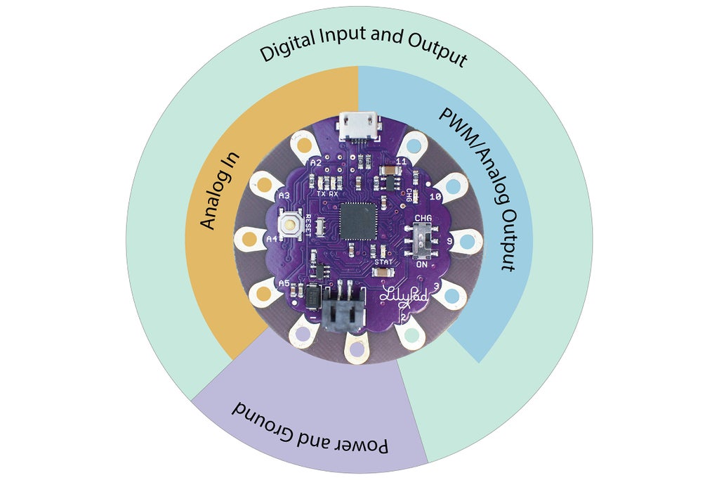
Remember that some pins on your microcontroller are able to output a PWM signal and some are not. A PWM signal is what makes your LilyPad able to output a seemingly analog signal. In order for the LED to be able to fade you need to connect it to pins 3 - 11 of the LilyPad USB. If you need a refresher on what PWM means, take a moment to revisit the Introducing the Microcontroller lesson.
Step 3: Open Sketch

In Arduino navigate to:
File > Examples > Analog > Fading
Copy and paste the example sketch in a new window and save as FadingDemo.
Change the lenPin value from 9 to 3.
int ledPin = 3;
Step 4: Upload

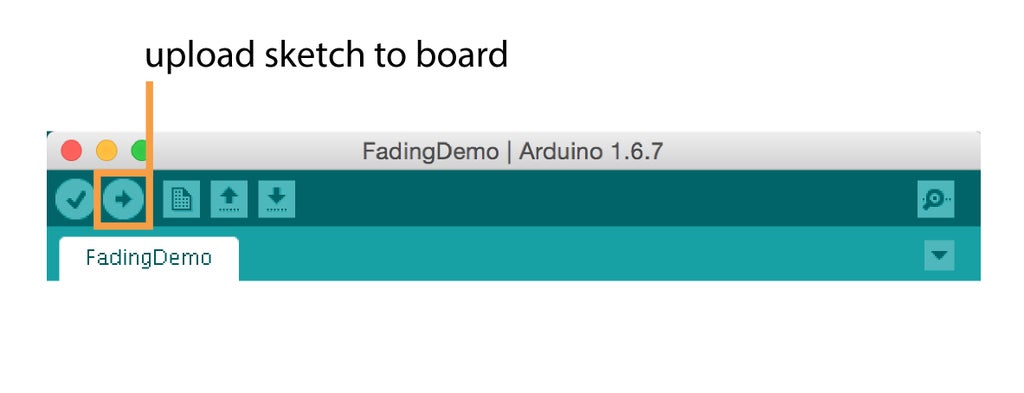
Turn the board on if it isn't already. Check your board, port and LED pin. When all looks good hit upload. The LED will start fading in and out. Snap a photo so you can share your circuit at the end of the lesson!
Step 5: The Code

There are a couple new things being implemented in this sketch. Let's first review some things that should start to look familiar.
Create and declare a variable for the pin number the LED is clipped to.
int ledPin = 3;
When outputting analog values with analogWrite(), you do not need to call pinMode() like you did in your previous sketches, so nothing happens here.
void setup() {
  // nothing happens in setup
}
For statement
Here is something new, this sketch uses a for statement. The for statement is useful for any repetitive operation, such as incrementing a value. The for statement is made up of 3 operations: create a variable, the condition, and then increment (or decrement). The code that is between the curly brackets and the increment executes if the condition is true. Let's take a closer look at what each of these operations do. Here is the for statement in its entirety:
  for (int fadeValue = 0 ; fadeValue <= 255; fadeValue += 5) {
    analogWrite(ledPin, fadeValue);
    delay(30);
  }
Operation 1: Variable
Declare a variable called fadeValue with the value of 0.
int fadeValue = 0 ;
Operation 2: Condition
Remember a variable holds a piece of data, in the first operation, you tell it to hold 0. This second operation compares the variable, which is equal to 0 now with 255. If it's less than or equal to 255, the code between the curly brackets and the increment gets executed. The "equal to 255" is put there so you make sure it goes all the way to 255 and doesn't stop at 254. Once the value reaches 256 by incrementation, the condition is no longer true. The for loop is exited and the board moves on to the next block of code.
fadeValue <= 255;
Operation 3: Increment and Execute
This is where the value gets incremented (or decremented). The combination of += is shorthand for fadeValue = fadeValue + 5. This adds 5 to the value that is being held in the fadeValue variable every time fadeValue is less than or equal to 255.
fadeValue += 5
If the condition is true, not only does the incrementation happen the code between the for statement's curly brackets gets executed.
    analogWrite(ledPin, fadeValue);
    delay(30);
The first time the for statement is executed fadeValue is set to 0. The second time it is 5, the third equals 10, fourth, 15 and so. This number correlates to the brightness of the LED which can be set 0 - 255. 0 being off and 255 being the brightest.
AnalogWrite()
AnalogWrite() is the function you call to write a PWM wave to an analog output pin. It takes two parameters (pin number, value). In this sketch it is saying, write to the pin your LED is connected to and use the value that is in our fadeValue variable (which is being incremented until it hits 255) to declare its brightness. This is how the brightness is notched up from each pass through the forstatement.
analogWrite(ledPin, fadeValue);
The delay here is delaying the next loop through the forstatement, slowing down the fading effect. At 30 milliseconds it happens so fast the fade appears smooth.
delay(30);
Step 6: Experiment

Cool, so now what? The code explanations may seem foreign and fuzzy so let's change some code to see it action!
Change the increment from 5 to 10 and see what happens.
for (int fadeValue = 0 ; fadeValue <= 255; fadeValue += 10) {
    analogWrite(ledPin, fadeValue);
    // wait for 30 milliseconds to see the dimming effect
    delay(30);
  }
Change the 30 in the delay() function to 200 and see what happens.
for (int fadeValue = 0 ; fadeValue <= 255; fadeValue += 10) {
    analogWrite(ledPin, fadeValue);
    // wait for 30 milliseconds to see the dimming effect
    delay(200);
  }
Step 7: Add Digital Input

Keep the LED on pin 3. Grab your snap switch, some alligator leads and make these connections:
switch --> pin 2
switch --> ground (-) LilyPad
Step 8: Upload

Open the FadeInputDemo sketch you downloaded at the beginning of this lesson and upload.
Open the serial monitor to watch the switch state print out. Snap the switch closed and the LED fades on and off. When the switch is open the LED stays off.


Step 9: The Vibe Board

By blinking and fading, you have now learned the basics of outputting a digital and analog signal to an LED.
Let's try outputting to something new like the vibe board. The vibe board has a tiny motor that vibrates when voltage is applied. It's great for haptic feedback and giving the wearer a notification that no one else will be aware of. Just like the LED, you can send varying voltage levels to it, but instead of getting brighter, a vibe board shakes at different intensities.
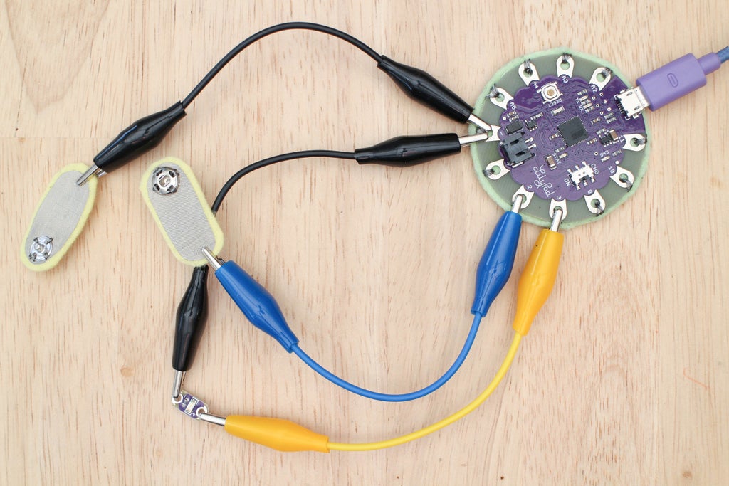
Step 10: Build Circuit

Make these connections:
switch --> pin 2
switch --> ground (-)
LED power (+) --> pin 3
LED ground (-) --> ground (-)
vibe board power (+) --> pin 9
vibe board ground (-) --> ground (-)

Step 11: Add Code to FadeInputDemo Sketch to Finalize

Copy and paste the FadeInputDemo sketch into a new window and save it as FadeInput2Outputs. Add the additional lines of code below to add the vibe board as a second output.
Create a variable for the vibe board's pin number. Put this with your other variables at the top of the sketch.
int vibePin = 9;
Call analogWrite() in the if/else statementand send the vibe board a value between 0 - 255. The vibe board needs a certain amount of voltage, so make sure the value you send it is 140 or above. Check out the image below to see where to put these two lines. They are highlighted so it's easier to see where they belong in the sketch. Double check to see where the curly brackets are!
analogWrite(vibePin, 140);
analogWrite(vibePin, 255);

Add line in between curly brackets of if portion of if/else statement.
 Add line in between curly brackets of else portion of if/else statement.
Step 12: Upload

Upload the sketch. The LED will fade on and off when the switch is closed and the vibe board turns on at its lowest intensity. When the switch is open, the LED is off and the vibe board turns on at its highest intensity.

Step 13: The Code
Let's do another quick review of what the code is doing since we added the vibe board.
Variables are declared and initialized with the PWM pin numbers the LED and vibe board are connected to.
int ledPin = 3;
int vibePin = 9;
The switch is connected to digital pin two.
int buttonPin = 2;
Create a variable to hold the switch's state.
int buttonState = 0;
Open the serial port at the rate of 9600 baud.
Serial.begin(9600);
Set the switch pin to an input and enable the internal pull-up resistor.
pinMode(buttonPin, INPUT_PULLUP);
Read whether the switch is open or closed and put the value in a variable called buttonState.
buttonState = digitalRead(buttonPin);
Print the switch's state in the serial monitor.
Serial.println(buttonState);
If the switch is closed, fade on and off LED and turn vibe board on at low intensity
if (buttonState == LOW) {
    for (int fadeValue = 0 ; fadeValue <= 255; fadeValue += 5) {
    analogWrite(ledPin, fadeValue);
    delay(30);
  }
    for (int fadeValue = 255 ; fadeValue >= 0; fadeValue -= 5) {
    analogWrite(ledPin, fadeValue);
    delay(30);
  }
  analogWrite(vibePin, 140);
}
Otherwise, if the switch is open dim the LED and turn vibe board on at high intensity.
else {
  analogWrite(ledPin, 100);
  analogWrite(vibePin, 255);
}
Step 14: Test Your Knowledge
{
    "id": "quiz-1",
    "question": "To fade an LED, what kind of pin does the LED need to be connected to?",
    "answers": [
        {
            "title": "digital",
            "correct": false
        },
        {
            "title": "PWM",
            "correct": true
        },
        {
            "title": "open",
            "correct": false
        }
    ],
    "correctNotice": "That's correct",
    "incorrectNotice": "That's incorrect"
}
{
    "id": "quiz-2",
    "question": "The code block in between the curly brackets of a for statement executes when the condition is...",
    "answers": [
        {
            "title": "false",
            "correct": false
        },
        {
            "title": "true",
            "correct": true
        }
    ],
    "correctNotice": "That's correct",
    "incorrectNotice": "That's incorrect"
}
Step 15:
Show any progress along with your final circuit using the FadeInput2Outputs sketch below! If you have any trouble comment below and we will work it out.


![Tim's Mechanical Spider Leg [LU9685-20CU]](https://content.instructables.com/FFB/5R4I/LVKZ6G6R/FFB5R4ILVKZ6G6R.png?auto=webp&crop=1.2%3A1&frame=1&width=306)


