

Introduction: Auto LED Switch


I had a requirement to control the operation of a couple of UV LED's in another project independent of a microcontroller.
Operation would be controlled by the light level and an LDR (Light Dependant Resistor), would be the sensor.
Only a handful of components are required which can be mounted on stripboard although I also created a PCB.
How does it work, well read on to find out.
Supplies
BS270 NFET
ZTX751 PNP
LDR (Light Dependent Resistor)
5k potentiometer through hole 3310C-001-502L
UV LED 3mm through hole - Qty 2
Pin headers - Straight through hole single row
Stripboard
For a PCB use SMD 1206 types for Stripboard use through hole components.
12K resistor
1K2 resistor - Qty 2
47R resistor - Qty 2
10n capacitor
22 SWG (21 AWG/0.71mm), Tinned copper wire (TCW).
May prove more cost effective to buy a range of values rather than individual values unless you already have them available. Some components may also have a MOL greater than the quantity specified in the component list.
No affiliation to any of the suppliers, feel free to obtain the supplies from your preferred supplier if applicatble.
Links valid at the time of publication.
Tools
Saw
Needle files
Sanding paper
Craft knife
Soldering Iron
Solder
Wire cutters/strippers.
Long nose Pliers
Track cutter and/or 3mm drill bit.
Marker
Magnifier
Stiff short bristle brush
Know your tools and follow the recommended operational procedures and be sure to wear the appropriate PPE.
Step 1: The Schematic

The light sensor is an LDR (light dependant resistor), which is connected as the lower end of a series circuit with a series resistor and potentiometer at the upper end to form a potential divider with the tap point at the top of the LDR.
A potential divider is a circuit whose output voltage is fraction of the input. In this case its composed of 3 series resistors supplied with 5V.
The variation in the light level changes the resistance of the LDR, more light the lower resistance and less light the higher the resistance. For this LDR used the resistance ranges from ~39R to ~350kR subject to lighting conditions.
The light detection threshold that determines at what level of brightness the LED's illuminate is adjusted by the potentiometer in the potential divider.
We can calculate the voltage at the tap point with the following equation:
Vtap = Vin * Rldr/(Rldr+Rs+Rpot)
We can apply typical values for the LDR and the potentiometer at min/max ranges not including component tolerance which will add some variation. The tighter the tolerance the smaller the component variation from its nominal value.
Vtap min = 5V * 39R/(39R+1k2+0R) = 157mV (LDR and potentiometer at min values)
Vtap max = 5V * 350k/(350k+1k2+5k) = 4.913V (LDR and potentiometer at max values)
The tap point of the potentiometer is connected to the NFET (BS270) which has a typical gate threshold (Vgsth), of 2.1V (1V min, 2.5V max).
Setting the potentiometer at its midpoint of 2.5K, (allowing manual adjustment either side of this value). If the LDR resistance varies from 1K to 4K then this variation will result in a voltage range of 1V to 2.6V, which will switch on the NFET. The exact switch on point will be subject to the Vgsth of the particular NFET.
The drain of the NFET is connected to a 12k resistor which acts as a pull up.
When the NFET is switched off (Vgsth < 1V), the base of the PNP transistor is pulled high by the 12k + 1.2k resistors thus reverse biased and switched off and the LED's are also off.
When the NFET is switched on (Vgsth between 1V to 2.5V), the midpoint of the 12k & 1.2k resistors are pulled low switching on the PNP transistor and the LED's.
The series resistor for the LED's (Rled), is calculated from the voltage drop of the other components.
Vled = 3.1V, Vcesat = ~1V therefore Vresistor = 5V - (Vled + Vcesat) = 5 - 4.1 = 900mV.
The transistor is not in full saturation due to the 1k base resistor limiting the base current to < 200uA.
The maximum recommended LED current (Ifmax), is 20mA, therefore Rled = Vresistor/Ifmax = 900mV/20mA = 45R
45R is not a standard value and the next value that maintains the current under 20mA is 47R (E6 or E12 series).
Step 2: Breadboarding

Prior to making a permanent circuit I would build it on a solderless breadboard which is excellent for assessing the idea and making any changes quickly.
Once I am happy with the circuit I would transfer it to a stripboard circuit.
Step 3: Stripboard


The circuit can be mounted on stripboard as an alternative to a PCB using through hole passive components.
All being well the circuit should work first time if a methodical and careful build is carried out, however, in the event that it fails to function refer to the schematic and troubleshooting tips.
With a track cutter cut the required points on the tracks and verify isolation with a DMM on continuity/resistance mode.
Using TCW solder the wires between the required points on the board and verify continuity with a DMM on continuity/resistance mode.
If unexpected shorts are identified visually check with a magnifier for incomplete cuts, copper slithers or solder bridges and remove with a scralpel or short bristle brush.
Mount the passive components.
Mount the pin headers.
Mount the potentiometer.
Visually check with a magnifier and DMM to ensure the correct component values are used.
Check across the potential divider network with a DMM in resistance mode and shorting link across the LDR pins for a resistance of 1k2 to 6k2 when the potentiometer is varied. If there is no variation in the resistance check for an open circuit wiper on the potentiometer.
If all is well set the potentiometer to it's midpoint.
Replace the shorting link with the LDR and verify the resistance of the network with and without light for a resistance of ~1k2 to ~356K. If there is no variation in the resistance check for an open circuit in the LDR connection.
Mount the transistors, ensuring they are correctly orientated.
Fit the LED's (ensure correct orientation), and LDR either on sockets, pins or board subject to requirements.
Without power check across the supply pins with a DMM on resistance to ensure no shorts exist.
Find and eliminate any shorts identified.
Apply power ensuring the correct voltage (5V), and polarity.
Expose the LDR to a bright light if not already done so, the LED's should be off.
Sheild the LDR from the light if not already in this state, the LED's will come on.
Step 4: Troubleshooting
In the event of an issue check both visually with a magnifier and electrically with a DMM initially in continuity/resistance mode without powering the circuit.
Using the schematic as a guide check for any opens and shorts with a DMM and ensure the active components are correctly orientated.
Once powered.
If the LED's do not behave as expected check the following:
Check that the voltage on the gate of the NFET is >Vgsth (~3V), when the LDR is covered and <<Vgsth (~0.3V) when exposed to a bright light.
If Vdrain =~0V under all conditions check for a Drain/Source short circuit.
If Vdrain =~5V under all conditions check for an open Drain.
If the conditions on the inputs and outputs of the NFET behave as expected check if there is an open circuit to the base of the PNP transistor.
It's always possible that a faulty component could exist rather than a build fault, if in doubt double check.
Step 5: PCB
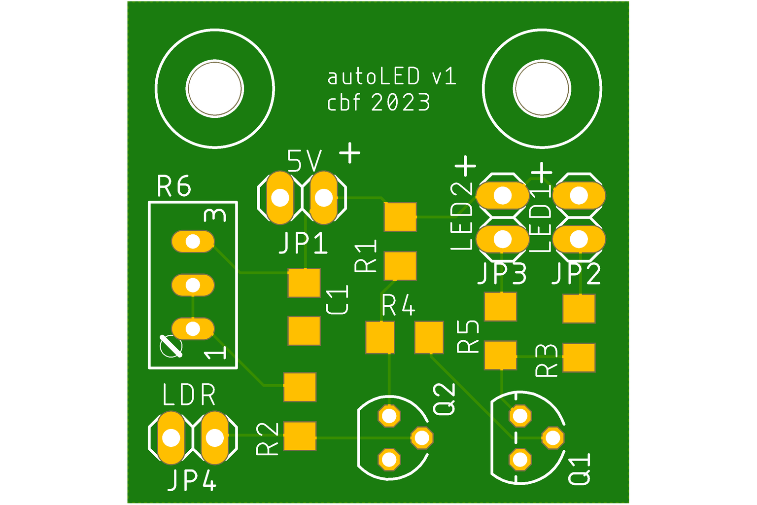


The PCB was designed using EagleCAD and the PCB was fabricated by OSHpark.
The majority of the passive (resistors/capacitor), components are SMD 1206 type with the exception of the LDR and potentiometer.
The active components (transistors), are through hole mounted.
As the LDR and the LED's in the application are located remotely from the circuit the PCB has the provision to mount pin headers for ease of assembly.
All components were manually soldered.
Mount the passive components.
Mount the pin headers.
Mount the potentiometer.
Mount the transistors, ensuring they are correctly orientated.
Fit the LED's (ensure correct orientation), and LDR either on sockets or direct the pins or board subject to requirements.
M3 mounting holes are included.
If there are any issues with operation check that the components are correctly positioned and orientated and that there are no unexpected open or shorts circuits. Both by visual inspection with a magnifier and electrically with a DMM.
Step 6: Finally
As a standalone or part of a larger project.
Hope you found this of interest.
That's all for now.

![Tim's Mechanical Spider Leg [LU9685-20CU]](https://content.instructables.com/FFB/5R4I/LVKZ6G6R/FFB5R4ILVKZ6G6R.png?auto=webp&crop=1.2%3A1&frame=1&width=306)


