

Introduction: Build Your Own "Weasley" Location Clock!


Ever since I was 8 years old, I've loved Harry Potter, and the world that JK Rowling built with her books. I always felt like I related to Harry's friend in the book, Ron Weasley, and I especially loved that Rowling tied the wizarding world into the real world.
I wanted to try and bring a piece of that world in to my own (while also geeking out with raspberry pi's and GPS!), which led me to starting this project of recreating a prop in the book.
This project is an Internet of Things Location Clock (or Whereabouts Clock or Weasley Clock). Rather than having 2 hands that give you the time of day, this clock has a hand for each member of your family or group, and displays the hand over wherever that person is. My clock, for example, has 2 hands (one for me and one for my wife) and shows locations for Home, School, my Parent's house, our favorite bar, the opera house (my wife and I volunteer for the opera), etc.
This Location clock works through a raspberry pi, that subscribes to an MQTT broker that our phone's publish events to. Our phone (running the OwnTracks GPS app) sends a message to the broker anytime we cross into or out of one of our waypoints that we have set up in OwnTracks, which then triggers the raspberry pi to run a servo that moves the clock hand to show our location.
This instructable is my part build journal - part how to on how to make your very own "Weasley" location clock. I put this together using ideas I picked up from allie.fauer with her instructable on a IoT Location Picture Frame, and also from jessyjones with their instructable about their own Weasley Clock.
Let's get started!
Step 1: Tools and Technology

I've seen a couple different approaches to this clock idea, so I took a little bit from several different projects.
I'll get into the software details in the next steps, here are all of the hardware pieces used.
- An old beat up clock, or clock shell.
- 2 Sail Winch Servos (special servos that can turn 360 degrees)
- 1 Raspberry Pi Micro-Computer (I used a Raspberry Pi model 1-B+)
- 1 Adafruit PWM/Servo Pi-Hat (link: https://www.adafruit.com/products/2327)
- 2 Screw mount servo gear hubs (link: https://www.servocity.com/770-clamping-hubs)
- 4 Acetyl 48 pitch hub mount gears. Two of them mount to the servos, two of them are connected to the brass tubes that turn the clock hands. (link: https://www.servocity.com/48p-acetyl-hub-mount-sp...
- 2 K&S Hobby Brass tubes. I used the 1/4 inch and 9/32 inch diameter tubes, since they can fit in to each other.
- 2 #10 1 1/2 inch machine screws with nuts.
- 1 sheet of AlumaMark gold sheeting.
- 1 sheet of 1/8 inch acryllic (make sure to get clear acryllic, because you'll have to see through the sheet to fit the gears together later on).
- 1 1/8 inch rubber grommet (for the top level clock hand)
Step 2: Clock Scavenging


For my Weasley clock, I wanted to give it a more authentic and old-fashioned look (like it's been in the family for a while or something like that). I originally wanted to find an old shell of a grandfather clock, but in our current apartment we don't have room for something quite that big. After searching craigslist for a few weeks, I eventually found a mantle clock someone was selling that had broken down and was beyond repair. A phone call and some tinkering later, I had an old-fashioned clock to use!
Step 3: Designing the Clock Face


The clock face was the one piece to this that I knew exactly how I wanted to look. I admit, my photoshop skills aren't quite up to snuff to make this completely from scratch, so I surfed the interwebs for a while, and eventually found a design pattern I liked.
This design came courtesy of GinnyLovegood1 (link here). I downloaded the jpeg of the picture they had designed, imported it into photoshop, and cut out the face from the rest of the picture. Since it was just a regular old jpeg (and didn't have any layers like a PSD), I had to find the Harry Potter styled font-type, so that I could replace some of the destinations with what I wanted. Some more photoshop magic later, I had my design all set! I then converted the photoshop document to a vector, and made an Adobe Illustrator vector to work with!
I wanted the clock to look as much like an authentic antique as possible, so I decided to etch the design onto metal.
You can take several different approaches in etching this out. The easiest method was to etch the design with a CNC laser engraver. I originally bought a sheet of brass to etch out, but the CNC laser wasn't strong enough to etch solid brass. After looking around online for a little while, I found an alternative metal to use, Alumamark! Alumamark is thin, flexible aluminum sheeting that is designed for etching with CNC lasers! I found some gold colored alumamark metal that was relatively inexpensive (about the same price as the brass sheeting I found earlier) and within a week I had my metal!
Sadly, I don't have a laser engraver, so I took my illustrator file to the Omaha Do Space, and etched it out with their laser CNC cutter.
Lastly, I had to cut the design out from the alumamark sheet. Unfortunately, none of the CNC routers I had access to had the strength to cut through aluminum sheeting, so I had to do this part by hand. To keep the metal stable when cutting this with a jig saw, I clamped the metal on to some scrap wood I had on hand, and cut a rough circle around the whole design. I did a little more detail work with some tin snips, and I had my clock face!
Step 4: Making the Clock Hands


I cut out some rough test versions (see the first two pictures on this step) and after a little bit of sanding and finagling of both the tubes and the hands, had working clock hands (albeit, a little ugly).
The idea I had about these clock hands, is that they would have a circle on one side that would have each user's picture on it, and then the arrow on the other side to point towards wherever the person is. I made a quick Photoshop document with a general design, and then converted it to a CNC-friendly vector graphic in Adobe Illustrator. I attached the illustrator file, photoshop file and png versions of the hands.
Once I had the design for my clock hand put together, I went back to the CNC laser cutter at the Omaha Do Space, to get them cut out! I'm using 1/4" birch plywood cut into 12"X12" pieces to cut into the clock hands.
I admit, this was the first time I ever had anything cut out via CNC (everything prior had just been engraved), so my first couple of passes on the laser cutter were less than ideal. With a little bit of help from the Do Space folks, I had my design set up correctly in the laser cutter software, and had my clock hands cut out! My settings for the laser cutter were a little over the top, so I ended up scorching the wood more than I had wanted to. Since I'm painting these black though, I wasn't too picky about the burn marks!
I ran into a few problems after coming back from the Do Space. I didn't realize that the birch plywood would be as brittle as it actually was, and in my haste to make the design of the clock hands in photoshop/illustrator, didn't make the holes in the original design. Because of this, when I tried to drill the hole for the bottom clock hand, the entire hand broke apart. I tried this with several different hands I had made (all of differing sizes) and unfortunately the hole I needed to drill was just too big.
To work around this, I cut a bit of left over acryllic to the same width as the clock hand, and drilled the hole through that. I then glued the broken clock hands on to the front of the acryllic, painted the whole assembly with black spray paint, and mounted the whole assembly onto the brass tube. With the top clock hand, I didn't have to worry about any of this, so I attached a rubber grommet that was the same diameter as my 1/4" brass tube, and stuck that on top!
With the clock hands painted, I printed out two small pictures of myself and my wife to attach to the clock hands. With a little more gluing and finagling, I had my finished clock hands set up on the clock and ready to rock and roll!
Attachments

Step 5: Software Setup - Static IP on the Raspberry Pi and Node-Red

To drive the Magic Clock, we're going to use a raspberry pi controlling several servo motors. I'm using a Raspberry Pi 1 B+ running raspbian wheezy, but any version Pi should work for this.
After flashing the SD card, and installing raspbian, I wanted to set a static IP address for the clock so that I can easily get to it from an ssh session if I need to make changes. I won't go into detail on how to do that, but you can find fantastic instructions on giving your Pi a static IP address here.
With a static IP address set on my micro-computer, it was time to install the main software app that will be doing the driving on this project, Node-Red. Node-Red is a Node.js package set that makes connecting devices, services, and web APIs a snap! You can find the Raspberry Pi specific install instructions here, though make sure you know what type of Raspberry Pi you are using, and what version of Linux you have running on it!
First step is to log in to your Pi and bring up your Pi's terminal (either via SSH, or plugged directly into the machine). You'll want to install any updates sitting out there for Raspbian with the command:
sudo apt-get update
After installing updates, we want to start the installation process for Node-Red. Since my raspberry pi is the older 1 B+ model, my first command is to navigate to the older debian archive for Raspberry Pi 1 B+.
wget http://node-arm.herokuapp.com/node_archive_armhf....
This starts a download for the debian package, which you can open with this command:
sudo dpkg -i node_archive_armhf.deb
After that, we need to install the rpi version of python to get Node-Red to play nice with our GPIO pins (more important later on in this instructable).
sudo apt-get install build-essential python-dev python-rpi.gpio
Lastly, we can install node-red. Don't worry if this install takes an abnormally long amount of time! Since my Pi wasn't being overclocked or anything, it took almost 20 minutes for the entire install to complete.
sudo npm install -g --unsafe-perm node-red
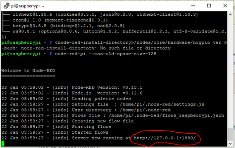
With the version of Node-Red installed that we need, let's fire it up! Because of the constrained memory on the Pi, we need to run Node-Red with the pi-specific "node-red-pi" command. This gives us the ability to add an additional argument that sets at what point Node.js will begin to free up unused memory (that's what this "max-old-space-size" argument is in our next command. Anyways, let's start up Node-Red!
node-red-pi --max-old-space-size=128
After a few moments, your Pi window (or ssh session) should look something like my screenshot with the red circle! The circled URL is important, this tells us where we need to go to access the Node-Red control board! 127.0.0.1 tells us it's the Pi's local IP address (most computers automatically set their own self-referenced address as 127.0.0.1). Go to another computer that is on the same network as your pi, and in a web browser, go to your Pi's URL on port 1880 (so for example, if your router assigns 192.168.x.x IP addresses (like say 192.168.0.100), then you would go to http://192.168.0.100:1880 in the web browser of your other computer. This internal IP should be what you set when you set the Pi to have a static IP address! If everything installed correctly, you should see a window similar to the second screenshot of my web screen!
With Node-Red now installed, we want to set it up as a service on our pi that starts automatically when you boot the machine up. We'll be using the auto-start capability that's in the built in systemd capability. You need to first check to make sure you have systemd configured on your machine.
sudo systemctl daemon-reload
If you receive a message stating that the command systemctl cannot be found, you have to install systemd!
Here's the command for installing systemd.
sudo apt-get install systemd systemd-sysv
Now, you'll download the 3 required service files to their correct locations:
sudo wget https://raw.githubusercontent.com/node-red/raspbian-deb-package/master/resources/nodered.service -O /lib/systemd/system/nodered.service
sudo wget https://raw.githubusercontent.com/node-red/raspbian-deb-package/master/resources/node-red-start -O /usr/bin/node-red-start
sudo wget https://raw.githubusercontent.com/node-red/raspbian-deb-package/master/resources/node-red-stop -O /usr/bin/node-red-stop
Then after downloading those files, we need to make the two scripts executable:
sudo chmod +x /usr/bin/node-red-st*
Lastly, we'll reload the systemd daemon and then enable Node-Red to run automatically!
sudo systemctl daemon-reload
sudo systemctl enable nodered.service
Our pi is now set up with node-red to run automatically on startup!
Step 6: Software Setup - CloudMQTT Broker Setup


With our Raspberry Pi (almost) completely set up, it's time to get MQTT up and running!
MQTT (Message Queuing Telemetry Transport) is a really nice messaging protocol that uses a publisher/subscriber model for sending machine to machine messages on spotty connections (See first image above). The main thing I really like about it is the amount of documentation out there about it, and that's it's very lightweight on data usage. I have it running on my phone 24/7, and it barely takes about 1 megabyte of 4G data per month!
In order to use this messaging protocol, we first have to set up a broker that our phone will publish messages to. You can setup your own MQTT broker on the raspberry pi, but I've found this solution to be a little tougher when it comes to security. The open source software that runs the MQTT broker (Mosquitto) supports SSL and TLS encrypted connections, but setting it up to run as a default was a pain in the butt, and I wanted to keep this setup as simple as possible. Also, I'm using a Raspberry Pi 1-B on this project and running the Mosquitto software through Node-Red was very taxing for my Pi. So for this project, we're actually going to setup a hosted broker through CloudMQTT!
I really like using this site for anything MQTT related. They have several plans to choose from (depending on your amount of usage), and for this particular project, we're able to run the whole thing on their FREE plan with up to 10 connections!
To set up your CloudMQTT plan go to this link, and select the cute cat plan by hitting the "Try now for Free" button. Name your broker instance (I named mine Owntracks, because that's what I'm using it for) and hit create!
That's all for our broker setup, though stay logged in to your cloudMQTT account. We'll need the info from our account for our next step, connecting our phone to the broker!
Step 7: Connecting Android Phones to Our MQTT Broker


For GPS services on this project, I decided to use OwnTracks. It's a free app available for iOS and Android devices, and it's very easy to set up and start your MQTT connections!
Here is how to set up Owntracks on an android phone. If you have an iOS device, skip to the next step to find the iOS instructions.
First, you have to download and install the OwnTracks app from the Google Play Store (link here). After it's installed, open the app, hit the settings bar in the top left corner, and hit the option "preferences" (See slide 2 on this step).
Once you bring up the preferences panel, select the option "Connection" and in the Connection panel change the Mode to "Private MQTT" (slides 3, 4 and 5)
With OwnTracks still up on your phone, open an internet browser window, and log in to the new CloudMQTT account you created in the previous step. Once you log in, go to your control panel and bring up the details on the MQTT instance you created from the previous step (slide 6)
Use all of the login settings on the details page of your CloudMQTT instance to fill in the connection settings in the OwnTracks app. For example, in the host section of the OwnTracks connection settings, put the server listed in the CloudMQTT details (mine is m12.cloudmqtt.com). The port you connect with will be just the standard port listed in the CloudMQTT details (not the ssl port, unless you want to set up an SSL connection between the two).
Here is a quick list of what goes where between CloudMQTT and OwnTracks:
| OwnTracks | CloudMQTT |
|---|---|
| Host | Server |
| Port | Port (standard, not ssl) |
| Use Websockets: | Keep disabled |
| Authentication: | Enabled |
| Username | User |
| Password | Password |
| Device ID: | whatever you want |
| Security Options: | Keep TLS turned off |
Any other settings I didn't list can be set to their default values.
Once you have the correct settings put in, bring up the Websocket UI on your CloudMQTT console. If everything is set up correctly, you should get a new MQTT message when your phone connects to your MQTT broker and updates it's position!
Step 8: Connecting IOS Phones to Our CloudMQTT Broker


Now that we have our CloudMQTT broker set up, lets connect Owntracks on our device to the broker!
If you are using an android device, go back to the previous step where I outline setting up OwnTracks on android devices.
The first thing you need to do is download and install the OwnTracks app from the iOS AppStore. There are a couple of different variations of this app in the AppStore (OwnTracksCTRL for example) but I just downloaded the vanilla copy of OwnTracks for iOS.
Once you open up OwnTracks, it'll have you connected in Public mode by default. Go ahead and select the "i" in the top left hand corner (see first screenshot) and then hit the "Settings" option in the info panel (second screenshot).
This part kind of tripped me up for a bit (to be honest, I'm not a huge fan of the UI design on the iOS version of this app compared to the android version. Personal preference!). You'll want to click/touch right where it says "Mode: Public" (third screenshot), NOT on the little i with the arrow on the right hand side of the Mode selection (pretty intuitive, right?) Once you select that, you should see a little tab on the bottom of the screen, where you can select from "Public", "Private", and "HTTP" (fourth screenshot). Select the option "Private", hit done, and you should see some additional connection options come up in the connection settings window (See fifth screenshot).
With OwnTracks still up on your phone, open an internet browser window, and log in to the new CloudMQTT account you created in the previous step. Once you log in, go to your control panel and bring up the details on the MQTT instance you created from the previous step (slide 6)
Use all of the login settings on the details page of your CloudMQTT instance to fill in the connection settings in the OwnTracks app. For example, in the host section of the OwnTracks connection settings, put the server listed in the CloudMQTT details (mine is m12.cloudmqtt.com). The port you connect with will be just the standard port listed in the CloudMQTT details (not the ssl port, unless you want to set up an SSL connection between the two).
Here is a quick list of what goes where between CloudMQTT and OwnTracks:
| OwnTracks | CloudMQTT |
|---|---|
| Host | Server |
| Port | Port (standard, not ssl) |
| Use Websockets: | Keep disabled |
| Authentication: | Enabled |
| Username | User |
| Password | Password |
| Device ID: | whatever you want |
| Security Options: | Keep TLS turned off |
Any other settings I didn't list can be set to their default values.
Once you have the correct settings put in, bring up the Websocket UI on your CloudMQTT console. If everything is set up correctly, you should get a new MQTT message when your phone connects to your MQTT broker and updates it's position!
Step 9: OwnTracks - Setting Up Regions


Now that I have my connection set up between OwnTracks and my MQTT broker, I want to set up geo-fence areas that will be the trigger points for when the clock hands should turn. This helps minimize the amount of moving pieces my raspberry pi will have. I've seen similar projects where someone grabs the GPS location that's sent to the broker, and then compares it to their own database of coordinates for verification. This is a perfectly valid approach, but it just adds additional steps on the Pi that I don't want to set up. Keep it simple!
On the OwnTracks main app page, hit the menu button on the top left hand side, and select the option "Regions" (On iOS, select the option on the bottom menu pane that says "Regions").
When the region window comes up, hit the plus sign in the top right corner of the screen to add a new region. Give the region any name you'd like, though keep in mind that the name you attach to the region is the name you have to reference when we get to the setup on the raspberry pi, so keep track of it! With newer versions of OwnTracks on android, the application actually links up with google maps, so if you hit the tracking icon in the top right section of the region setup page (see third screenshot), you can put in an exact street address and use that as your latitude and longitude coordinates!
Unfortunately, this functionality isn't on the iOS version that I can see. If you need to add a region, and you aren't currently at that region when adding it, there's a pretty useful way of grabbing Lat and Long values from Google Maps! Bring google maps up on a computer, find whatever location you need to map to a region, and then right click on that area and select "What is here". This should bring up both the address, and the exact Lat and Long coordinates for you to add to a region on your phone manually! I know, it's a little more work than on android, but tough it out!
Once you have your lat and long coordinates, you have to specify the radius of the region (in meters I believe). The region can be as big or small as you want (one of the regions I set up is the entire city of Chicago!)
IMPORTANT: Lastly, at the very bottom of the setup page (middle of the setup page for iOS), make sure you check the option to share! If you don't have this turned on, then if you enter or leave a region, the name of where you are entering or leaving isn't sent in the MQTT update, so your clock won't know where you are!
Step 10: Node-Red Workflow


The node-red flow for this setup was fairly simple in it's finished format, but took me a good while to figure out and have work routinely.
The flow starts with the connection to the MQTT broker with the MQTT node. This node is pretty self explanatory, but make sure your MQTT node is subscribed to the correct topic. For my clock, I wanted the hands to only move to the locations during Owntrack's transition events (right when you enter or leave one of the waypoints). Owntracks creates a separate topic for these events that's always MQTT-topic/event (so for example, mine was owntracks/userID/deviceID/event). As long as you subscribe to that topic with your MQTT node, you should only pick up messages when you enter or leave one of your waypoints.
When the MQTT node is triggered from the broker, a JSON string is sent to node-red with all of the necessary info from your device. JSON (JavaScript Object Notation) is just a data-interchange format that organizes all of your content in a manner that is easy to read both for you and a machine. Here's one of the JSON strings that was sent from my broker:
{"_type":"transition","tid":"at","acc":18.788334,"desc":"Home","event":"enter","lat":00.00000,"lon":00.000000,"tst":1480793788,"wtst":1477007711,"t":"c"}
For my clock, really the only parts of the string that I need are the location and whether I'm entering or leaving. In this JSON string, that's the two sections "desc" (for description) and "event". I can't really do a whole lot with just a string, so I need to convert the string into an array of JavaScript Objects.
To convert this string into objects, use the json function node that comes standard with the node-red-pi installation. This parses through the JSON string for you, and formats each string into a group of objects.
For this setup, the JSON string parser feeds directly into a switch node. This node takes the newly created object msg.payload.event and checks if that object is set to leave or enter. If it's set to enter, then the flow is directed to a second switch node that checks the value of the object msg.payload.desc. The switch node then feeds into whichever location matches up with the desc object value so that it can move the hand. If in the first switch node the msg.payload.event object is set to leave, then the flow immediately moves to setting the hand to "Travel". I then have node-red run a system callout (like if I was calling something from the terminal) that runs a python script, and passes a variable of the msg.payload.desc location. The python script I have (see next steps for python script) that picks up the variable and knows where to move the clock hand based off of that.
When the flow moves the hand to "Travel" a trigger node is also activated that counts for 6 hours. If msg.payload.event hasn't been updated (from when I enter another known location) after 6 hours, then the flow activates the servo to move the hand to "Lost", and then sets another trigger. The second trigger counts for 24 hours while waiting for an updated msg.payload.event. If it doesn't receive an update in that 24 hours, it finally moves the hand to "Mortal Peril". Bit of a gag if I have to go on a trip for work or if I turn my phone off for a few days, but other than that, should be pretty clear!
Step 11: Moving the Hands to the Correct Positions - Part 1


For me, this part was by far the most challenging: how to get the individual clock hands to move freely of their own accord while remaining stacked on top of each other?
I spent a good deal of time looking at previous Weasley clocks that had been designed for inspiration. The majority of the whereabouts clocks I had seen either used display screens to show the clock hands, or light-up displays to show the different locations. I really wanted my clock to have moving pieces though, to give it more of a "real" antique look.
I finally found a design that had been done by two other fellow magic clock makers. This design relies on tubes of varying circumferences stacked within each other and controlled by specialized servos (sail-winch servos, used for rc sailboats) that position the clock hands. The thing I really like about this design, is that you can still add as many hands as you like (provided you have enough space in the clock for the additional servos), so I can add additional hands in the future without much fuss!
For servos, I used 2 - GWS S125 1T 2BB Servos. These servos are perfect for what I need, since I need full 360° rotation (most servos only have a range of about 180°) while still being accurate. GWS unfortunately doesn't offer these servos directly off their site, so I ordered them off of AliExpress.
For the tubes that fit within each other, I used K&S hobby brass tubes. You can find these types of tubes at any hobby store, RC store, or online. For my clock, I used 9/32" and 1/8" diameter K&S tubes.
I cut a mounting block for the servos and tubes out of a scrap piece of 1/2 inch plywood that I had sitting around. Wasn't the greatest looking block, but I was impatient and didn't want to wait 3 weeks for when the CNC cutter was going to be available at the Do Space. The block mounts on to the door on the back of the clock shell, and the servos fit into the slots on the block. I made sure to space the servo openings so that the gears that mount on to the servos can connect to the brass tubes and turn the clock hands.
Step 12: Moving the Hands to the Correct Positions - Part 2


My servos are now connected to the mounting block that's on the door of the back of my clock! Each servo then has a large acetyl gear mounted on to the servo shaft (the big black and white plastic gears in the first picture). The top gear is connected to a spacer hub to stagger the two gears more since they are connecting within the same area.
In the first picture, you can see a hole I cut roughly in the middle of the mounting block. This is where 1 side of the 2 K&S brass tubes (set inside each other) will fit. The other side of these tubes go through a small piece of acrylic for stability, and then through the clock face. On each one of those tubes is a smaller acetyl gear hooked up to a screw-in gear hub. Those hubs then fit onto the K&S tubes, so that when the servo turns, the tube rotates!
Unfortunately, the Raspberry Pi 1 B+ I'm using only has 1 GPIO output pin that can supply a full 5 volts of output, and I need 5V to drive each of these servos. Thankfully, Adafruit makes a Servo Hat that can take care of supplying the additional outputs for the servos, and this one fits right on top of the Raspberry Pi! You can find that servo hat here.
When the Pi-Hat came in the mail, none of the inputs and outputs were soldered on, so I had to break out the soldering iron and try to fit this thing together. I was a little nervous, because I had never had that much success with soldering, but thankfully it all worked out!
The last slide in this step is a quick video, showing how all of the pieces fit together. Enjoy!
Step 13: Moving the Hands to the Correct Positions - Part 3

With the hardware (mostly) setup and ready to go, I had to get the software side to play nice.
The adafruit pi hat I picked up came with it's own python library for driving the servos. If you end up using the same pi hat that I used, there's a really helpful reference section here.
You control servos with Pulse Width Modulation (PWMs). Without getting too much into the nitty gritty, PWMs are signals sent at a steady pulse in whatever frequency you need to control electronics like LED lights and servos. By changing the length of time between the high and low signals that are sent to the servo motor, we can control how far the servo's spline turns, which then points the clock hand wherever needed. The best resource I've seen yet on PWM is this article on sparkfun's learning site. Check it out!
With the python library that's supplied by adafruit, I'll set a bit of python code for each hand position I need, then call them from a system command node in node-red.
The python code treats the PWM instances as their own objects, so every time I need to set a hand's position, I'll create a new PWM object. Before jumping in to the code, here is everything I need done everytime a clock hand position needs to be set.
- Create a new PWM object
- Set the exact frequency of the PWM object
- Set when in each pulse the signal should change from low to high and then back from high to low
- Close the PWM object, so that the clock hand stays in whatever position I need.
I attached a video of the hands moving when I was running a test script. I also attached code for one of the hand movements. I admit, python isn't my best language, so most of this was copied from the example code provided by Adafruit in their drivers for the Pi-Hat.
Attachments
Step 14: All Finished!


With the clock hands set in place, and the python code loaded up, my Weasley location clock is all set!
Please vote for me for the CNC, Remix and Epilog VIII Instructable contests! Depending on the feedback I receive from this, and the other social media sites I post this project too, I might start my own kickstarter or indiegogo drive to sell a version of this clock both in self-assembled kits and finished products to fellow tinkerers and Potter fans!
Hope you enjoyed my instructable, this was a great project to do from start to finish!

Runner Up in the
CNC Contest 2016

Participated in the
Remix Contest 2016

Participated in the
Epilog Contest 8


