

Introduction: Build a One-Handed Soldering Tool | Effortless Soldering With Only One Hand (How To)


In this project, I will walk you through how to build a neat soldering iron attachment that allows you to effortlessly bond wires while only utilizing one hand for both the solder and soldering iron.
For the best quality read, check out this article on my homepage here. If there's a pop-up, just simply click dismiss at the bottom. Also, don't forget to subscribe for free to support my work! :)
Step 1:
A Quick Preview
The benefits of this project, which I am calling the Solder Sustainer, is that if you are able to solder while only utilizing one hand, it means your other hand is free to hold whatever wire or component you are trying to solder. It’s certainly made my life easier.
(If you’re not totally sure what soldering is, check out this link.)
Here’s a preview of the final project. :D
Step 2:


There are two touch sensor buttons near the tip of the 3D printed motor housing to allow easy reach and touch. I’ll explain how the sensors work later. The solder can be extruded onto the soldering iron tip through a simple extruder gear mounted to a stepper motor.

Step 3:
If you’re still not convinced of this tool’s awesomeness, here’s sick a soldering montage. Mind the meow.
Step 4:
(I am aware that the joints are a bit cold, but that is no fault of the project. I just should’ve turned up the heat a bit more.)
Hopefully now you want one for yourself. Luckily for you, this is a completely open-source project! But first, let me explain how it works.
Working Concept
The main concept here is that a small NEMA17 stepper motor will extrude solder through a long tube onto the tip of your soldering iron. The only problem in making it is that solder is very thin, so it would require a unique mechanism to be able to firmly grasp and move the solder.

I took inspiration the greatest tool ever. Of course, I’m talking about 3D printers.
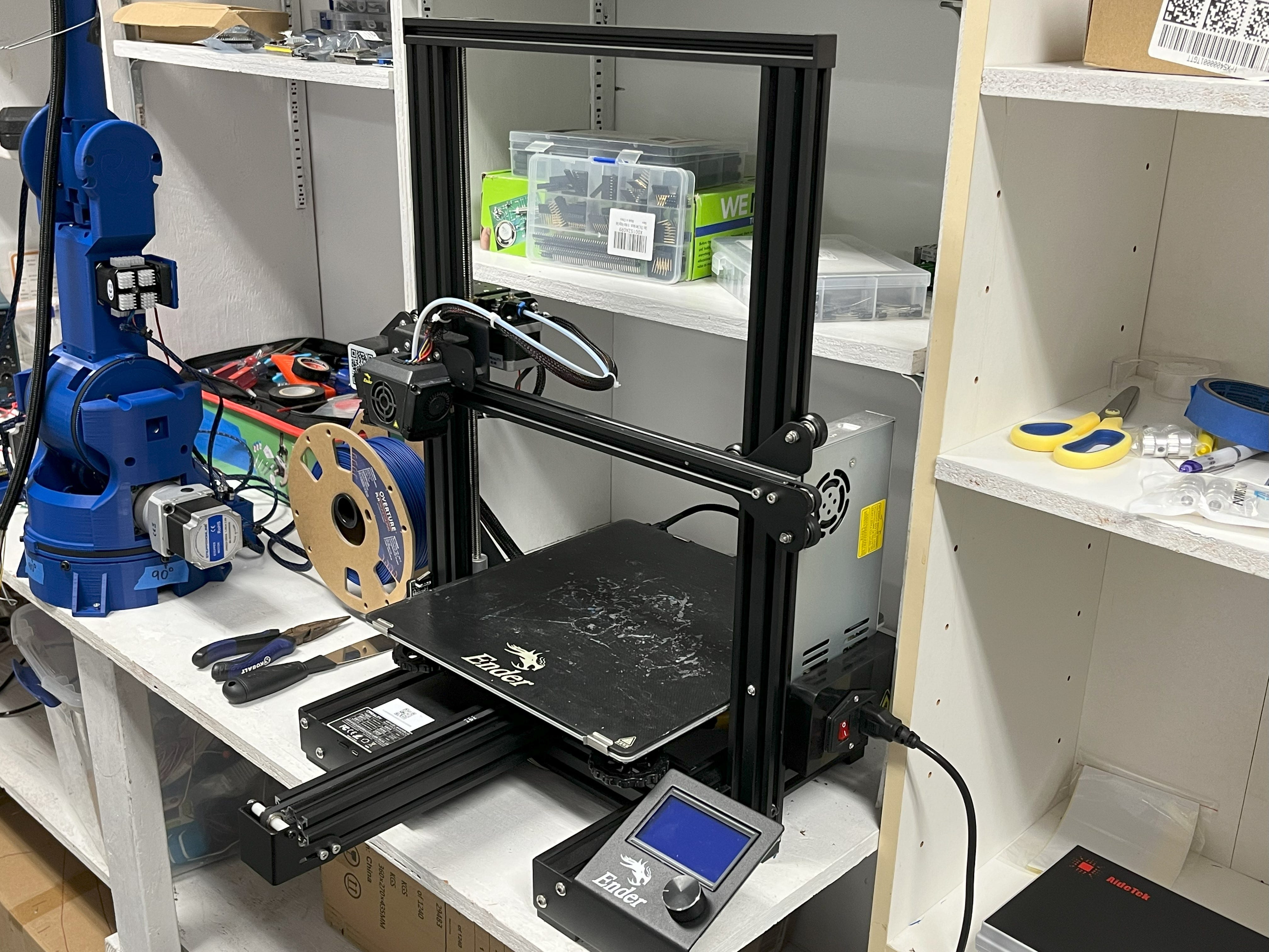
3D printers have a similar problem in that they have to extrude filament through a long tube to feed the hot end of the extruder.

The solution for 3D printers was to create a small spring-loaded mechanism to constantly press the filament against the extruder wheel on the NEMA17 as seen above. All that I’ve done differently for my device was compress it to fit on a soldering iron, added a solder wheel, and made everything 3D printable.

Understanding the Hardware
To make this device, all we need is a stepper motor, stepper motor driver, a few electrical components, some 3D printed parts, and of course a soldering iron.
All of the CAD files for this project can be found for free here on my Thingiverse.
Here’s how all of the electronics work together.

For a better-quality image and downloadable option of the image, go to my GitHub here. If you’re interested in downloading the raw schematic and layout so you can make edits and use it for your future projects, you can download the KiCad files from this page. Just please be sure to credit me and check out the readme file :).
Having a problem with downloading the KiCad schematic and layout? Let me know! This is the first time I’ve uploaded editable board files and could’ve made a mistake.
Now that you’ve seen the schematic, let me explain its design. Everything in the big ESP32-S3 box at the top of the image is the microcontroller. Instead of making it component by component like seen here, you can also just buy a Devkit. However, I decided to do it this way because it’s a fantastic learning experience and allows me to make a more efficient shape when designing the PCB (Printed Circuit Board). But, if you’re just more interested in the final result of this project, you can take out everything in the ESP32-S3 box and replace it with something such as below. It will work the same, just note you'll have to make some edits to the PCB.

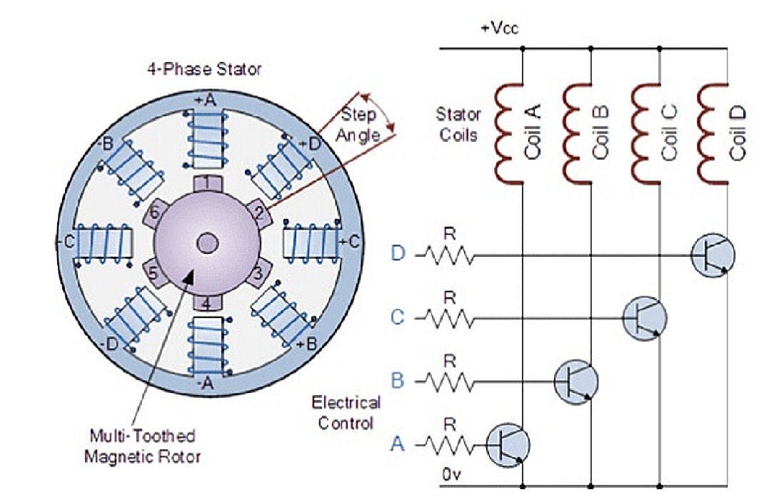
For driving the stepper motor, I decided to use a A4988 stepper motor driver IC. The purpose of this is to convert the low voltage STEP and DIR signals from the microcontroller into high voltage ones that are able to drive the steps of the stepper motor. More details here.
*Credit is linked above.
Since soldering irons run off AC, we will also need a rectifier to convert AC voltage into steady DC voltage. A common rectifier is none other than a simple charging block (the part of a phone charger that goes into the wall). This will convert household AC voltage into a steady 5VDC. Although, you of course can also power the device just fine through the on-board USB-C (5V). The cable just may get in the way some.

Then from there, we can use a common voltage step-up module to boost that 5V into the 12V necessary to power the stepper motor. The other benefit though, is that our microcontroller circuit requires 5VDC. This means we can also tap into it prior to boosting the voltage and get the correct power for our computing circuit in addition our motor.

The last mystery in our circuit is the touch sensor buttons. These work because the human body is a conductor of electricity. By placing our finger over two conductive pads, with one being connected to power, the power will flow from that pad to the next. The only issue is that the new voltage that is able to make it to the other pad is quite small. Enter transistors.

*B-Base, C-Collector, E-Emitter
If we connect the low voltage pad to the base of the transistor, it will allow current to flow from the collector to the emitter which would be large enough to be detected with our microcontroller.
Building the Board
Now that you hopefully understand the circuitry, it’s time to get to the layout.
(If not, leave a comment and I’ll do my best to help.)


This is what the finished PCB looks like. If you’re interested in learning more about PCB layouts and routing, check out Robert Feranec. He’s an excellent designer and I’ve learned a lot from him.
The fabrication/Gerber file for the PCB is on my GitHub here.
To download, click “download raw”.

Of course, to fabricate these boards we will need to go through a PCB manufacturer. As usual, I chose PCBWay.

They offer excellent quality PCBs for the cheap and reasonable price of $5 for 5 boards, as well as a variety of other services such as CNC machining, assembly, 3D printing, and many more. Not to mention their simple checkout process. All I had to do was go to PCBWay.com, click on quick-order PCB, and upload the Gerber/Fab file for the board. Or alternatively, just go here which I have saved in my favorites bar.

When they arrived a few short days later, they looked fantastic!

With a quality PCB built and ready, it was time to get to assembling it.
Note: If you’d prefer to skip this step, you can actually have PCBWay assemble it through their assembly services. The BOM (Bill of Materials) at the bottom will have all the parts you will need. Also, make sure you click the Stencil button at checkout if you’d like to use a stencil for soldering it yourself.
First, we can use a stencil to apply solder paste over all of the different SMDs (Surface Mount Devices). We can then melt this paste into hard solder by applying heat with a heat gun later. Just note this isn’t a requirement. You can solder everything on using some solder and a soldering iron, it’ll just be more difficult since everything is so small.
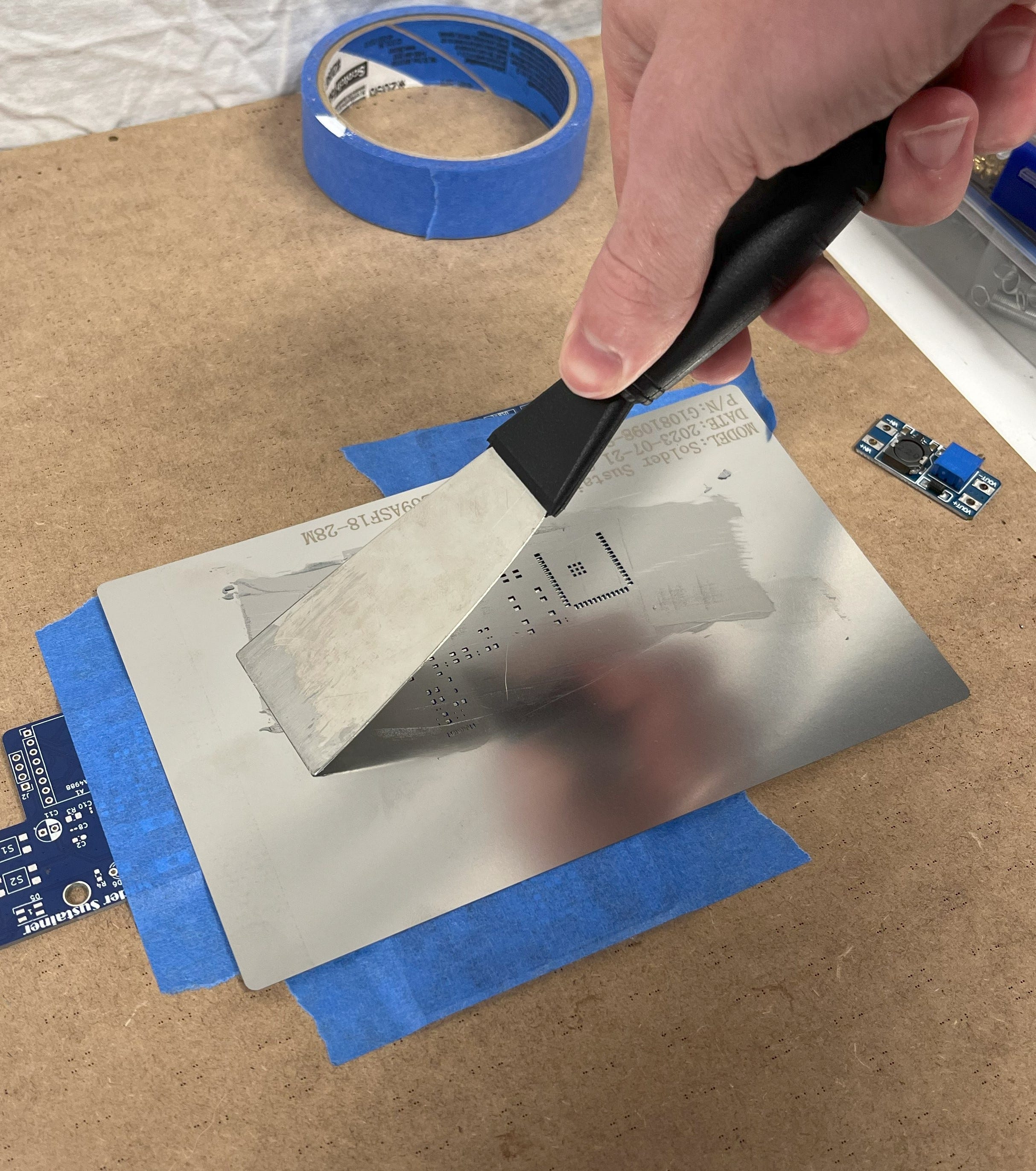
Then, all we need to do is place the components and heat them up. You may want to print out the SMD Reference Sheet when doing this. This is useful because using it, you can match the component to the number corresponding to it on the board. It can be found by downloading it from the schematic or downloading it here.
The list of the exact components I bought for building this project can be found here as well as the BOM at the bottom, but I’ll add some important notes in the BOM so be sure to look at it. However, it’s completely fine to not have the exact same component so long as they have the same value.
For example, two 10 microfarad capacitors but one of them is 1mm longer than the other. If you do this, you will need to accommodate for the different size by changing its footprint on the PCB.

*One is bigger, one is smaller. The values are the same.
Step 5:
Sorry the quality isn’t great, I’ll get a better angle next time. Just be sure to place the components in their places on the PCB using the Reference Sheet linked above.
The rest of the components must be hand soldered. If you don’t have a larger capacitor to fit C11, feel free to just use a SMD one. It should fit fine; the rating is 100μF. Just be aware that it connects to the Vmot (motor voltage).
(Also be sure to check the output voltage of the step-up module so that it reads 12V after plugging in the USB-C.)
Something else important to note is D1’s polarity. This is an important diode, so make sure that the small horizontal line on the front of it is facing up, toward the dot on the board.

For attaching the 5VDC rectifier (iPhone block), I just used some super glue.

Just like that, we have a finished PCB!
If you’re wondering why there’s a small wire between R3 and R4 or noticed any other small differences between your board file and what mine looks like, it’s because I made a few mistakes while designing my board. Not to worry, everything was fixed on the one you’ll be downloading.
Building a Version 2?
Obviously, no project is perfect and I wanted to share some strengths and weaknesses I’ve found while using this device. It seems to be reallyyy good at soldering through-hole pins, soldering together loose wires, and is pretty decent on larger surface mount devices. Although that being said, it’s obviously not super ideal for precision applications such as really small capacitors and such.

I’ve gotten a lot of awesome feedback so far through social media with some great ideas for a Solder Sustainer v2 if this project continues to receive support.

If you would like to see a version two, be sure to subscribe, like this post (homepage), and leave a comment letting me know. I’d love to make a v2 in the future some with some features such as:
- Built in fan for smoke removal.
- Better extruder trigger such as a foot pedal or pressure sensor.
- Built in solder lights to eliminate any shadows on the joint you’re binding.
- More compact power regulation for lighter weight.
- Some kind of flux dispenser.
- More sleek design/compact circuitry so it’s more comfortable to hold.
I’d love to continue hearing your feedback so let me know what you think in the comments below. I also ask my followers to vote on what my next project should be via my Instagram, so be sure to check it out.
Assembly
Now to assemble the 3D-printed parts.
First, mount on the extruder gear for the NEMA17, and screw it into place on the shaft of the motor. From there, we can pop two M4 nuts into their places on the solder tube and screw it to the motor mount.

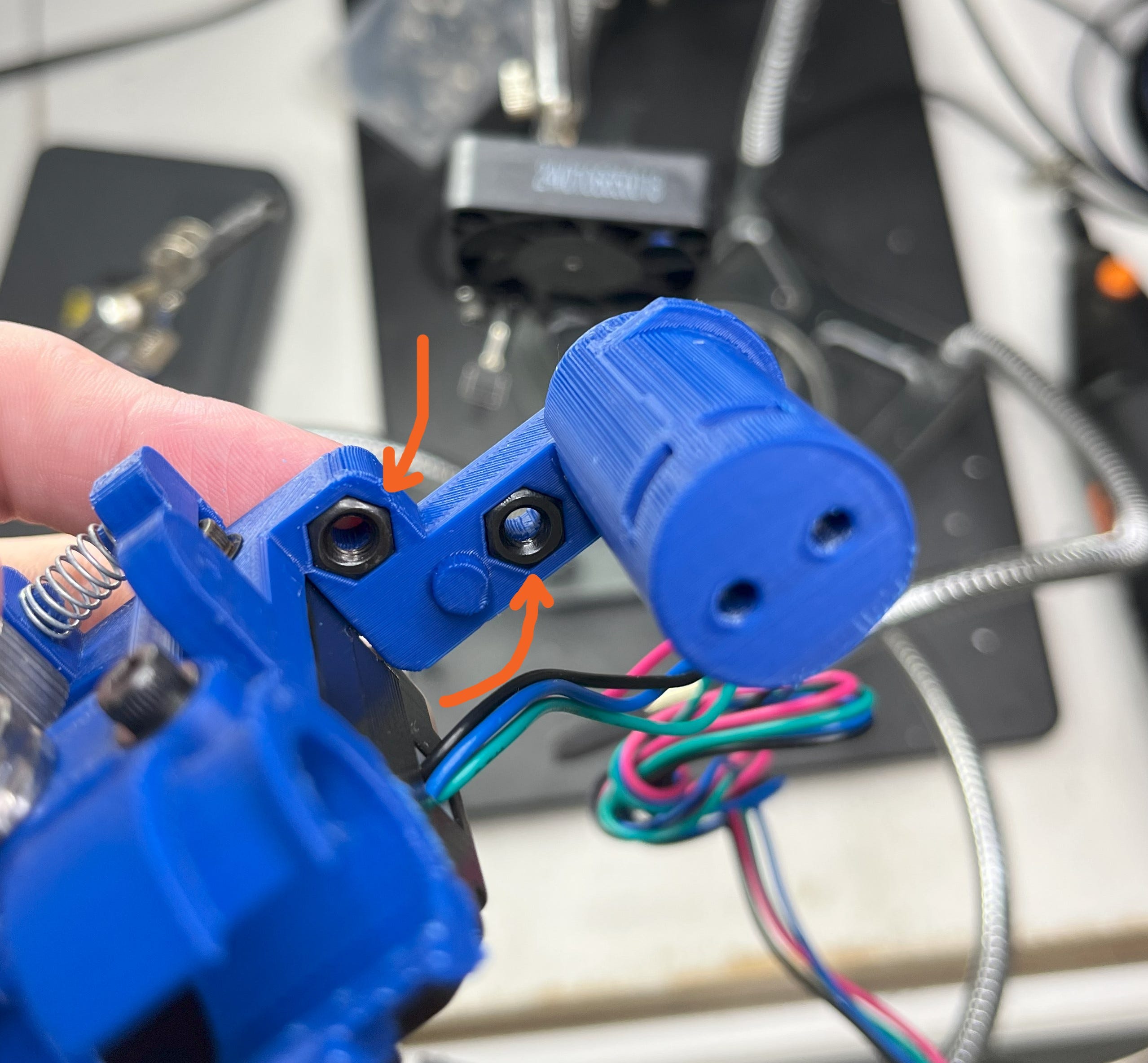
Next, grab the tensor bracket and press the threaded insert into the M4 hole using your soon to be upgraded soldering iron. As stated in the BOM, this insert needs to be 4mm or less, so it doesn’t stick out the bottom.

After that, get your 4x13x5mm bearing and shave off some of the middle. You don’t have to do this step, but I’d recommend it so that the solder doesn’t slip as easily. I recommend running it against a drill or using a Dremel to do this.

Then insert a spring between the tensor and mount, and screw in the bearing using a short M4 bolt, no longer than 8mm. (7mm if you don’t use a washer.) For the spring, you could probably find one that would work from an old 3D printer or large pen. However, I just got a small kit since I knew I’d use them in future projects. An investment for science! But a huge variety of them would work.

From there, grab two M3 nuts and push them through the solder roll holder. This is so that you’ll be able to screw a cap on to prevent it from falling out.

Similarly, get two M4 nuts and pop them into their places on the back of where the PCB will go.
Then just slide on the solder roll and screw in the cap. If your solder roll has a different diameter, don’t worry. I’ve attached STEP/SolidWorks files in the CAD so you can make edits.

Next, screw in the PCB and insert the soldering iron. To insert it, just slide it in from the bottom then turn it when the nob reaches the slot in the middle.

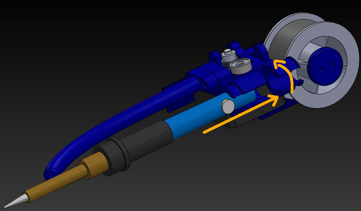
To secure it, we can use two zip-ties.

Also note again that I’ve attached the STEP/SolidWorks files on my CAD page, meaning you can make edits to the parts if needed. So don’t worry if you don’t have the exact same equipment.
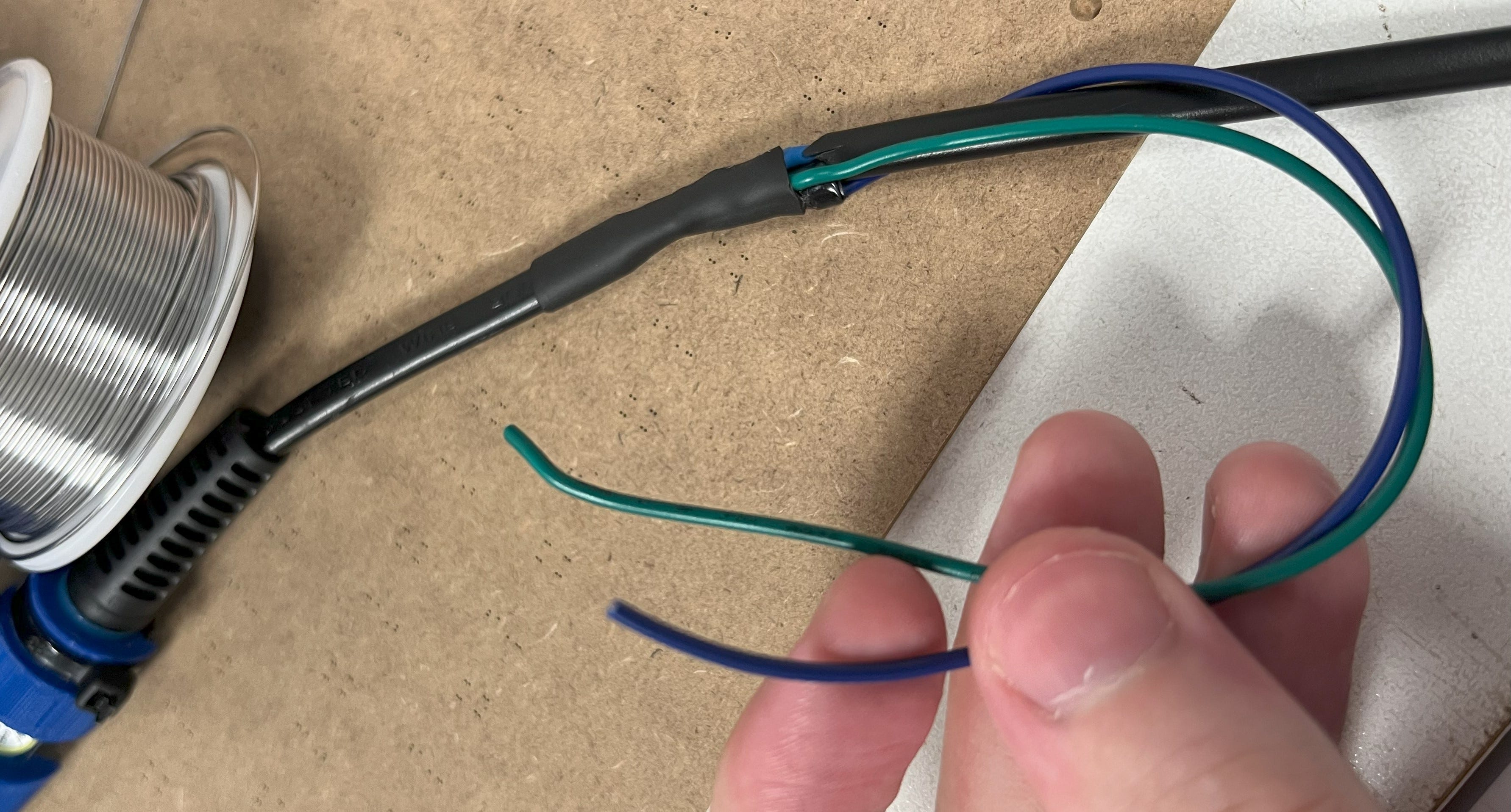
*OPTIONAL: This is how to connect the solder sustainer to your soldering irons AC current. If you plan to just power the device through the USB-C cable you can skip this step. Make sure to read through the steps before doing it.
- UNPLUG THE SOLDERING IRON. I cannot stress that enough. If you leave it plugged in while working on it, you’ll experience a very unpleasant and possibly lethal120AC. Just unplug it!
- Cut the wire connecting to the soldering iron about 5cm away from where the wire goes into the iron.
- Strip both sides of the wire so that about 1cm of the wire is exposed.

- Using a separate wire, make a connection from one of the irons wires to one end of the rectifier and the other to the other. There is no polarity with AC so don’t worry about which one goes where.
- Connect back together the two wires of the soldering iron so it can receive power again. I understand this can be challenging without a second soldering iron, so do your best to knot them together or bind them another way. If you think this will be too hard, just power the device off of the USB-C.
- Wrap that those wires up! You can use an unholy amount of electrical tape for this, or some heat shrink if you have it. Just make sure it’s secure, you DON’T want to touch any exposed AC wire when soldering.
- Then strip the two ends of your new wires and attach them to the two prongs of the rectifier. Make sure the prongs of the rectifier are VERY securely insulated afterwards, as they will be connected to household power as well.
- That’s it!


Then you’re done! Not too bad of an assembly compared to my robotic arm project, haha.

Programming
If you were happy by the simplicity of the assembly, you’ll be even happier now. If not, you’ll still be happy.
This is probably one of the simplest programs I’ve ever written. I think it took about three minutes haha. It’s so simple in fact, I won’t even attach it to my GitHub. Well, I will but I wouldn’t need to. You know what I mean. Here’s the program.
#include <AccelStepper.h>

const int stepPin = 4;
const int dirPin = 5;
const int forPin = 6; //Pin connected to the forward button
const int backPin = 7; //Pin connected to the backward button
const int rgbLed = 38; //Cool multi-color LED (optional)

const int extrudeSpeed = 75; //Speed in steps/sec to move the motor (200 steps/rev)

AccelStepper extruder(1, stepPin, dirPin); // (Type:driver(1 is default driver), STEP, DIR)

void setup()
{
  extruder.setMaxSpeed(1000);
  pinMode(forPin, INPUT_PULLDOWN);
  pinMode(backPin, INPUT_PULLDOWN);
}

void loop()
{
  if (digitalRead(forPin) == HIGH)
  {
    extruder.setSpeed(extrudeSpeed);
    extruder.runSpeed();
  }
  else if (digitalRead(backPin) == HIGH)
  {
    extruder.setSpeed(-extrudeSpeed);
    extruder.runSpeed();
  }
  else
  {
    extruder.setSpeed(0);
    extruder.stop();
  }
}
Here’s how it works.
For this program we are using the Arduino IDE with the Accelstepper library, which is the same I used in my robotic arm projects. It just makes controlling stepper motors really easy. Basically, it’s a codebase that allows you to send out stepper motor pulses that correspond to a given speed or destination in steps. (Note the library must be installed.)
#include <AccelStepper.h>
Then create some variables as constant integers. We create them as a constants since they will not be changed at all from their initial values (they’re constant).
const int stepPin = 4;
const int dirPin = 5;
const int forPin = 6; //Pin connected to the forward button
const int backPin = 7; //Pin connected to the backward button
const int rgbLed = 38; //Cool multi-color LED (optional)

const int extrudeSpeed = 75; //Speed in steps/sec to move the motor (200 steps/rev)
Then we create an object for the stepper motor. I called mine “extruder”. This tells the library which type of motor it is, and which pins are the STEP and DIR pins.
AccelStepper extruder(1, stepPin, dirPin); // (Type:driver(1 is default driver), STEP, DIR)
Then set the type of pin each are (inputs), and the max speed. This isn’t really used in this program, but it’s required for the library.
  extruder.setMaxSpeed(1000);
  pinMode(forPin, INPUT_PULLDOWN);
  pinMode(backPin, INPUT_PULLDOWN);
Finally, there is an if-else chain for each of the different states the motor will be in. (Forward, backward, or stationary.)
  if (digitalRead(forPin) == HIGH)
  {
    extruder.setSpeed(extrudeSpeed);
    extruder.runSpeed();
  }
  else if (digitalRead(backPin) == HIGH)
  {
    extruder.setSpeed(-extrudeSpeed);
    extruder.runSpeed();
  }
  else
  {
    extruder.setSpeed(0);
    extruder.stop();
  }
That’s it! EZPZ.
(NOTE: When you plug in the device to upload the code, if your PC doesn’t recognize the device, it’s likely because the microcontroller isn’t in bootloader mode. The first time you plug in the module, you have to hold down the boot button > hit the reset button while it’s held > then release the boot button. You only have to do this once.)
So I’ve Built it, How Do I Use it Effectively?
If you’ve built it already, you must be wondering how you’re so awesome but also wondering how to get the most out of this device. Let me share what I’ve learned.
To get the most out of every solder with this device, I’ve learned it’s best to design the solder tube so that it barely misses the top of the soldering iron. Yes, misses. Here’s why:
- Solder only melts when it’s hot.
- When you’re soldering, you’re trying to apply solder to the joint, not the iron.
- If you apply solder to the iron without redirecting it, all of it will stick to it.
- Solder sticks to the iron more than a bare piece of metal because it is coated in flux from previous solders.
- Flux works by removing oxide films which form on the surface of metals being soldered.
- Lack of oxide films allows solder an easier path to flow, aka, not on the joint you’re trying to solder.
- For this, you have to have a way to both heat up the solder and not make continuous contact with the iron.
Failure to do this is actually why a lot of industrial versions of this device, which have been brought to my attention, didn’t work very well. They all seemed to direct the solder ONLY onto the iron, not the joint. I’m guessing because their tube is made of metal and not meant to flex/gets too hot, luckily printer filament is more kind. Here’s a quick video showing what I mean.
Step 6:
As seen here, the most efficient way that I’ve found to solder with this device is to direct solder onto/close to the iron, while next to the joint, using your middle finger. Then, as soon as that solder heats up, pretty much instantly, let go and extrude it directly onto the joint you’re soldering. You will also have much more control on where the solder is hitting the joint by using your middle finger to direct it, which will be useful in a large variety of situations. And you can trust me on this, I’ve experimented with a LOT of different ways to get the most efficient solder from this device.

*Pain
That’s all I’ve got for ya!
BOM
This is the Bill of Materials for my Solder Sustainer project.
I’ll put everything that you need to have here so that you don’t have to go scrolling around looking for the links I sprinkled in throughout the article.
- All the CAD can be found here. I’ve attached a STEP file for editing so that it can fit different soldering irons. In addition, I attached a SolidWorks file for each. Mess around with the sketch titled “THIS SKETCH” on the solder tube for easy adjustments. If you don’t have SolidWorks, the STEP file edits will work fine too.
- x1 short NEMA 17 stepper motor.
- x1 3D-printer/other extruder gear.
- x1 4x13x5mm bearing.
- x1 spring, huge variety of options.
- Obviously, a soldering iron. This is the one I used.
- You’ll need some solder with that.
- x1 5VDC output rectifier (Apple phone charger brick). (Don’t get this if you’re powering it via USB-C).
- Few zip ties (optional but helpful).
- M3 & M4 nuts and bolts.
- x1 M4 threaded insert. You’ll want a thin one no longer than exactly 4mm. If you can’t find one, you can do what I did and remove off half of a normal one haha. If you do that the ideal length is about 3mm. (The ones I linked are too long! I just put them there for reference.)
- x1 USB-C data cable for uploading the program/power if you choose.
- x1 USB power cable for hijacking the soldering irons AC current. (A power cable is a USB cord that doesn’t have any data wires.) If you can’t find one, you can just use any regular USB cable and cut off/ignore the data wires. (Don’t get this if you’re powering it via the USB-C).
- All of the part numbers and quantities for the Surface Mount Components (SMDs) and some other electrical parts can be found here through this link. Again, it’s completely fine to not have the exact same component so long as they have the same value.
- I’ve also linked some options through amazon for the other components needed for this project such as the voltage step-up module, motor driver, etc. in the link above.
Disclosure: These are affiliate links. I get a portion of product sales at no extra cost to you.
Now, some important notes:
- While it says the quantity is only a few for each SMD part, I recommend buying a handful. They’re super cheap, and that way you’ll have plenty for other projects/if you break one. Plus, if you order them all at the same time, you don’t have to pay twice for shipping.
- I ordered my parts through two different sellers because I was doing large orders with other parts, you are welcome to save on shipping and just pick one seller. It’s also important to note that not every seller has the same stock, I know LCSC had everything I needed, I’m not sure about Digi Key. Just note LCSC ships from China so shipping is a bit more. That being said feel free to do some deal hunting and let me know what you find.
- If you order the same USB-C connectors as I did, there are two little nubs at the bottom of them. Snip them off! The connector won’t fit right on the board if you leave them on. If you ordered different USB-C connectors, you’re probably okay, but I’d still check.
- If you want to do anything with wireless such as a wireless foot pedal, buy ESP32-S3-WROOM-1s instead of ESP32-S3-WROOM-1Us. It’ll come with an antenna.
- I used a 2N2222 NPN transistor, but you don’t have to! Almost any NPN transistor will do just as long as the pins/size line up. In the case of this project, the collector of the transistor needs to connect to the topmost pin. It’ll look like so.
- C-Collector Pin, B-Base Pin, E-Emitter Pin

That’s all! Thanks for sticking with me.

Thanks so much for reading! I hope this was a helpful and informative article. If you decided to do the build, please feel free to leave any questions in the comments below. If not, I hope you were still able to enjoy reading and learn something new!
Have constructive criticism? I’m always looking to improve my work. Leave it in the comments! Until next time.
Be sure to follow me on Instagram and subscribe for free to support my work! :)! :)


