

Introduction: CNC Machined and Bent Aluminum Raspberry Pi + Touchscreen Case


Welcome back to another Instructable and project from your friends at Narwhal Labs!
Narwhal Labs is sponsored by and located at TotalBoat HQ in Bristol, RI. Having a makerspace on-site at their location allows us to design and build projects to help with their business needs. Liam, our IT Space Wizard, Consuela, one of our warehouse associates, and Andrew, a maker at Narwhal Labs worked together to make a ruggedized aluminum case for a Raspberry Pi with a touchscreen. These cases will hang from packing stations to help TotalBoat track packing performance and accuracy.
Follow along as we learn how to machine aluminum, experiment with bending different types of aluminum, cutting acrylic, and 3D printing a mounting bracket to make the coolest Pi case you've seen today! A full build video with some additional details and some fun here at work is included. Plus you can watch us break some end mills :D
Supplies
- Raspberry Pi
- Raspberry Pi 7" Capacitive Touchscreen
- USB Pigtails USB AUSB C
- 1/8" Acrylic (for front and back panels)
- PLA or PETG filament for your 3d Printer
- 5000 series .09" aluminum
- Pop rivets and rivet gun
Step 1: Design and Machining Aluminum With Fusion 360 CAD and CAM.


First - huge props to Andrew for taking the time to learn Fusion 360 to design and do all the CAM work for this project. Are you new to Fusion? We recommend this video series by Lars Christensen from Autodesk - it's a bit dated but all the concepts still apply and the menus are pretty similar. It's a fantastic video series (and channel) that will get you from 0-60 in Fusion 360 in no time.
Andrew designed this entirely flat, though Fusion's sheet metal design features may take some of the guess work out of this process. Initially we designed this to use 1/16" end mills, but the machine speed (or lack of) and the fragility of that tooling made this difficult. Andrew adapted his design to allow us to machine with an inexpensive 1/8" o-flute end mill, and that did the trick for us.
We tested 3000, 5000, and 6000 series aluminum for machining and bending - and it was truly a goldilocks and the 3 bears scenario.
- 3000 series aluminum bent without stress fractures, but was very "grabby" and difficult to machine.
- 6000 series aluminum machined great, but was resulted in stress fractures when trying to bend the parts.
- 5000 series aluminum was *just right* - an excellent balance of machinability and bend-ability.
Special thanks to our friend Winston Moy, who helped us with our CAM recipe. We found a spindle speed of 22000 RPM, feed rate of 70IPM and a .01" DoC with a 1/8" O-Flute carbide end mill worked great for us. We also used WD-40 and air to help keep the router bit cool and capture some of the aluminum shavings while machining. The aluminum was fixed to a piece of MDF with blue tape and Super 77 adhesive - other workholding solutions will probably be just fine.
Want to machine your own? We've attached our fusion archives and vector files for you to give it a try. Check the first section for links to the pi hardware and display.


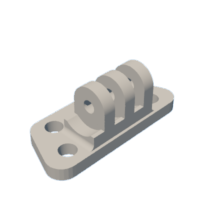
Step 2: Additional Components: Mounting Bracket and Front/Rear Plates


While optional, we 3D printed a mounting bracket for our specific application. Just print two of the attached STLs in the PLA or PETG filament of your choice, and put them together with a single 1/4-20 bolt. We also cut rectangular plates for the front and back. These can be made out of various materials, but we used acrylic for its easy machining and laser cutting properties. Files for these items are attached including a fusion archive of the front/rear plates.

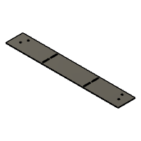
Step 3: Bending the Aluminum and Final Assembly


Once the machine work is all done, it's time for bending and assembly. You don't need a fancy sheet metal brake for this - all you need is a basic vice. Hand held brakes from the discount tool store work fine too, and we used a non-marring mallet to flatten things out a bit. Some of the parts we even bent by hand. Check for square once bent and adjust. It's better to not bend it enough and make small adjustments than it is to bend it too far and have to bend backwards.
The structure of the case is assembled with just a few pop rivets - nice and easy.
The raspberry pi and display are made for each other and bolt together with included hardware.
The USB headers get screwed into the case and plugged into the pi.
Lastly, the front and rear plates with the pi and display are attached. Some long metric screws fasten it all together with the built in threaded mounts on the back of the display.
Step 4: Put It to Use!


Combined with Liam's software, and Andrews case - we were able to implement this solution in TotalBoat's warehouse for tracking. This was a super fun and educational build process for us, and I'm glad we could share it with you here on instructables. Thanks to our wonderful friends at AvidCNC who support Narwhal Labs and helped us out with this fantastic machine to enable our projects.
Did you make your own? Share your experience with us in the comments! More details and some really great video work by our in-house video team - Kyle and Graz in the YouTube video. We'd appreciate if you could give it a watch and let us know if you liked it!

Participated in the
Metal Contest

![Tim's Mechanical Spider Leg [LU9685-20CU]](https://content.instructables.com/FFB/5R4I/LVKZ6G6R/FFB5R4ILVKZ6G6R.png?auto=webp&crop=1.2%3A1&frame=1&width=306)


