

Introduction: Converting the Radio-controlled Toy Car to Control Via WiFi. Stage 1


Problem statement
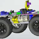
There is a radio-controlled toy car (like this one in the body of the Toyota Land Cruiser). It is required to make control of the toy car from the Android tablet or phone via WiFi.
How we will solve the problem
One of the most inexpensive chips for working with WiFi is ESP8266 (a link to an excellent resource) here we take it. I have the option ESP-12 (this one, link to WeMos D1 mini).
In a toy car there is two electric DC motors (one moves forward and backward, the second turns to the left, to the right) and four LEDs (two headlights at the front and two lights on the rear), I decided to control it using Arduino (link).
Motors operating from 5 V to 9 V, they consume 0.2 A under a load and 0.4 A when blocked. Respectively me suitable L293D motor driver (reference datasheet, one link, second link), just one chip L293D Me enough for both motors.
Toy cars power supply was originally from three AA batteries. I did not like this (I had to change batteries too often), so I decided to use lithium-ion batteries. You can take any battery, the main thing is that this battery is fit in the body of a toy car. 2 years ago I removed the not working battery from the old laptop Toshiba (I bought it in 2007). I disassembled the battery and took out a 6 Lithium Ion 18650 size batteries (useful link (in russian), another link, protect 18650 cell, recycle old laptop battery). On my pleasure all 6 cells 18650 were alive. Two batteries are perfectly fit in the body of a toy car.
To charge the batteries I decided to use the TP4056 module (datasheet reference).
It seemed to me a good idea also to equip my toy car with distance control sensors. I chose the ultrasonic sensor HC-SR04 (tutorial). It took me 2 sensors (forward, reverse).
Total required equipment:
- toy car — donor but it is better to take a larger toy - it will be easier to fit in;
- Arduino (MINI, UNO, NANO, MEGA — as you like to fit in the toy car, I personally still debugged on the Arduino UNO, and the final version did on the Arduino Nano) beginners guide, the original source;
- ESP8266 (I bought a clone WeMos D1 mini) reference, another link;
- motor driver L293D (reference datasheet) but it's better to look towards the L298N, if space allows (tutorial);
- a rechargeable battery (usually comes with protection), if as I have the 18650 and there is no protection, then protection against over discharge (link in russian) is also needed;
- battery charging module TP4056 (datasheet reference);
- ultrasonic sensor HC-SR04 or something else: SRF05, SRF06, DYP-ME007, URM37;
- additionally took me to the debugging: the joystick (tutorial) and text LCD display SPI/I2C 1602 (tutorial);
- small items: adapter for Arduino with screw terminals (this is for Arduino Nano), breadboard, prototyping boards for soldering 3x7 cm and 6x8 cm, resistors (0.5 W, ratings 220 Ω, 2.2 kΩ, 3.3 kΩ, 3.9 kΩ, 4.7 kΩ, 5.6 kΩ, 47 kΩ, 100 kΩ), LEDs (20 mA, 5 V), a toggle switch with 6 pins (I have MTS-202), button with 4 contacts, a field effect transistor (FET) NPN - I took IRLML2502), bipolar transistor (PNP - I took BC557C), precision programmable reference voltage source (TL431), Android phone or tablet, computer, super glue, baking soda, hot glue gun with glue, knife, screwdriver, soldering iron.
Solution of the problem
I divided the main task into subtasks:
- configure ESP8266, write a sketch for Arduino, decodes commands from a mobile device;
- write a program on Android, sending commands to a toy car (while with minimal functionality);
- write a sketch for Arduino controls of the motors using the L293D driver (to understand that something has to be done with PWM, since the motors are squeaking, correcting (spoiler - increasing the PWM frequency in Arduino) link (russian), link (arduino.cc), I recomend this link);
- combine the first 3 steps, get on the table a bunch of elements that reacts to the effect you have on the control element on the screen of the mobile device (the wheels are spinning);
- deal with ultrasonic sensors HC-SR04 (like everything is easy but in fact the method using pulseIn() is not suitable for us since it blocks the execution of the sketch for a long time, we use NewPing Arduino Library);
- assemble frankenstein on the table, image the result (for example in fritzing), debug;
- power supply;
- finish the application to control the toy car from the Android device (in fact I did it badly but, on the other hand, it works the same);
- you can start assembling a toy car.
Step 1: Configure ESP8266, Write Sketch for Arduino, Debug.


So, what is ESP8266 (a link to Wikipedia, ESP8266 AT instruction set) — is a popular and inexpensive chip, supports IEEE 802.11 b/g/n WiFi, a frequency of 2.4 GHz, a maximum transfer rate of 54 Mbit/s, is sold in versions with different amount of memory (datasheet). The processor frequency is 80 MHz, which is much larger than Arduino UNO (16 MHz). In general, we need a zero point zero possibilities of this chip to meet our needs.
Connect ESP8266 to Arduino UNO (1 physical UART port), at the ESP8266 module Tx connected to the digital pin 5 Arduino, and Rx to pin 6 (Figure 1.1).
Be careful when connecting the WiFi module ESP8266 - most of them are powered by 3.3 V. I have a module with a power of 5 V.
Why so? The matter is that Arduino UNO has only one UART, it also sits on USB, respectively, if you connect ESP8266 to pins 0 and 1, then sketch will not load - ESP will interfere (for Arduino MEGA this is not a problem). To make life a little simpler, we will use the SoftwareSerial library (I used this resource).
Figure 1.1 - Сonnecting my version of ESP8266 to Arduino
For experiments and setting up ESPs, in my opinion, such a sketch is good (see Listing 1.1).
Listing 1.1 - Broadcasting everything from the Serial port to the SoftwareSerial port and back
// connect the library for the program Serial
#include <SoftwareSerial.h>
// Let's give the program's Serial name and specify which pins it is located (RX, TX)
// Connect the pin of the TX module to pin 5, and RX to pin 6
SoftwareSerial mySerial(5, 6);
void setup() {
  // put your setup code here, to run once:
  Serial.begin(19200);
  while(!Serial){}
  mySerial.begin(115200);//The default connection speed is 115200
  delay(1000);
}
void loop() {
  // put your main code here, to run repeatedly:
  if(mySerial.available()){
    Serial.write(mySerial.read());
  }
  if(Serial.available()){
    mySerial.write(Serial.read());
  }
}
Accordingly, in the Arduino IDE, open the "Tools-> Port Monitor" (Ctrl + Shift + M) at the bottom of the window set the speed to 19200 and you can communicate with the ESP module using AT commands. After a little thought I decided for myself that it would be more convenient for me to work if the ESP module is in Access Point mode. Accordingly, the set of AT commands of the ESP module will be as follows:
- 'АТ' - Checking the connection to the ESP;
- 'AT+RST' - Reboot ESP.
Settings (they will be saved after the ESP8266 module is rebooted, accordingly they are done once manually):
- 'AT+UART_DEF=115200,8,1,0,0' - Configure the UART port of the ESP module - 115200 - speed, baud, 8 - number of data bits, 1 - number of stop bits, 0 - number of even bits, 0 - no flow control;
- 'AT+CWMODE_DEF=2' - 2 – Activate soft-AP mode;
- 'AT+CWSAP_DEF=”ESP8266”,”1234567890”,5,3' - Access point settings: ESP8266 - SSID (network name), 1234567890 - password, 5 - channel number, 3 - encryption type (WPA2_PSK);
- 'AT+CIPAP_DEF=”192.168.4.1”,”192.168.4.1”,”255.255.255.0”' - TCP/IP settings for the access point: IP address, default gateway, network mask;
- 'AT+CWDHCP_DEF=0,1' - Enable DHCP server: 0 - install softAP, 1 - enable DHCP;
- 'AT+CWDHCPS_DEF=1,2000,”192.168.4.2”,”192.168.4.15”' - DHCP server settings: 1 - to allow setting of address range, 2000 - lease time of IP address in minutes, initial IP address, final IP address;
TCP server settings, you need to set them after rebooting each time:
- 'AT+CIPMUX=1' - Allow multiple connections;
- 'AT+CIPSERVER=1,333' - Enable TCP server on port 333;
Sending data to the client:
- 'AT+CIPSENDEX=0,5' - We send the message. 0 - number of connection with the client, 5 - length of the message;
- '>xxxxx' - After sending the command, the response from the ESP ">" will come. After that it will be necessary to send to the port the message "xxxxx" consisting of the previously specified number of characters (message length).
The result of the ESP setup is shown in Figure 1.2.
Figure 1.2 - The process of configuring the ESP8266 with the AT commands
Now ESP8266 module is configured as an access point. You have a new WiFi network should appear, try to connect to it.
In principle, you can start writing a sketch for Arduino, which will send a request to the application on Android and process commands from it, debugging information, you can drop into the UART interface. In addition, I used for debugging a text LCD display SPI/I2C 1602 (tutorial).
SPI/I2C 1602 is a text display on liquid crystals, 16 columns, 2 lines, with a converter board, which allows you to control this display via the I2C interface. In principle, there is nothing complicated when working with it, with one small but important exception - with the LiquidCrystal_I2C.h library, as with some other clones of this library, my display did not work (February 2018). The maximum he did was write the first character in each line. After some time, I came to the conclusion that this is due to some changes in the updated Arduino studio (I have version 1.8.5), which in this library and some of its clones were not taken into account. In general, a suitable library was later found by a simple search, and this is LiquidCrystal_PCF8574.h. The layout looks like Figure 1.3.
Figure 1.3 - Connecting the WiFi module and text display to Arduino
In general, I have the following sketch for the exchange with the Android application (see Listing 1.2).
Listing 1.2 - Data exchange with the Android application via WiFi on the Arduino side
#include <LiquidCrystal_PCF8574.h>
#include <SoftwareSerial.h>

#define APSSID "ESP8266" //the name of the access point network
#define APPASS "1234567890" //access point network password
#define SRVPORT 333 //port on which the server will wait for the TCP connection
const int LCDADR=0x27;
const int RX_P=5;
const int TX_P=6;
const unsigned long tmtsrv=1000; //timeout response waiting from Android application
const unsigned long tmtwf=100; //timeout for a response from a WiFi module
unsigned long ct; //time, fixed from the beginning of timeout waiting
int com=0;//the executable command (0-no command, 1-waiting for response from the client)
SoftwareSerial mySerial(RX_P, TX_P); // create software UART RX-> 5 pin, TX-> 6 pin to // WiFi module
LiquidCrystal_PCF8574 lcd(LCDADR); //we connect to the LCD screen via I2C (address 39 (0x27))

void setup() {
  //Serial.begin(115200);// for debugging
  mySerial.begin(115200); //We begin to exchange with the WiFi module at a speed of 115200 baud
  mySerial.println("AT+RST"); //reboot wifi module

  lcd.begin(16, 2); //start the exchange with the LCD screen, we have 16 columns,2 lines
  lcd.setBacklight(255); // turn on the LCD backlight
  lcd.clear(); //clear LCD screen
  msglcd("Init...", "");
  delay(1000);
  mySerial.println("AT");
  delay(1000);
  if(mySerial.find("OK"))// if the WiFi module is ready
  {
    msglcd("WiFi module is", "ready");
  } else {
    msglcd("WiFi module", "dosn't respond");
    while(1);
  }
  /* The WiFi module is set up as softAP (in the access point mode) with the configured APSSID network name, APPASS password, channel number 5, password encryption - WPA2_PSK
needs to write validation of the access point settings.
We will allow many connections to the server (without this server can not be created)*/
  mySerial.println("AT+CIPMUX=1");
  delay(1000);
  mySerial.find("OK"); // clean serial buffer
  // create server
  String cmd="AT+CIPSERVER=1,";
  cmd+=String(SRVPORT);
  mySerial.println(cmd);
  delay(1000);
  if(mySerial.find("OK"))//if command passed
  {
    lcd.clear();
    msglcd("Server on", "port is up");
  } else {
    lcd.clear();
    msglcd("Server can't", "be created");
    while(1);
  }
  delay(1000);
  lcd.clear();
  msglcd("ready", "");
}
void loop() {
  // We ask where to go
  if(com==0)//If there is no command, then we send a request to the Android application
  {
    cleanRdBuf(); //clean the mySerial port buffer
    int res_code=WiFiSend("ready\n");
    switch(res_code)
    {
      case 0:
        com=1;//now waiting for a response from the client
        ct=millis();//timestamp
        //Serial.print(String(ct));//debug    ************
        //Serial.print("\t\t");//debug        ************
        break;
      case 1:
        msglcd("Can't   ", "connect ");
        com=0;
        break;
      case 2:
        msglcd("Can't   ", "send    ");
        com=0;
        break;
      default:
        com=0;
        break;
    }
  }
  if(com==1)
  {
    if(((mySerial.available()>0)&&((millis()-ct)>=tmtwf))||((millis()-ct)>=tmtsrv))/*we expect a response of at least tmtwf msec and not more than tmtsrv msec*/
    {/* reading data from the WiFi module, so far we do not care about the availability of the connection, sometime we add*/
      //Serial.print(String(millis()));//debug    ************
      //Serial.print("\t\t");//debug        ************
      String rcv_buf=WiFiRcv();
      //Serial.print(rcv_buf);//debug       ************
      //Serial.print("\t\t");//debug        ************
      ParseCommand(rcv_buf);
      com=0;//waiting for a new command from the application
      cleanRdBuf();//clean the mySerial port buffer
    }//end of timeout processing condition
  }//end of processing condition for waiting command response (com == 1)
}
void msglcd(String fl, String sl)//display messages on LCD fl – first line, sl – second line
{
  lcd.setCursor(0, 0);
  lcd.print(fl);
  lcd.setCursor(0, 1);
  lcd.print(sl);
}
void cleanRdBuf()//clean mySerial port buffer
{
  while(mySerial.available())
  {
    mySerial.read();
  }
}
int WiFiSend(String send_buf)//send message via WiFi
{
  String cmd="AT+CIPSENDEX=0,";//request WiFi module AT+CIPSENDEX=0,5
  cmd+=send_buf.length();//(0 is the connection identifier, 5 is the length of the message)
  mySerial.println(cmd);
  delay(50);
  if(mySerial.find(">"))// if the command has passed, then you need to give a message
  {
    mySerial.println(send_buf);
  }else{
    //error of command AT+CIPSENDEX=0,5
    return 1;
  }
  delay(100);
  if(mySerial.find("SEND OK"))
  {
    //it is OK
    return 0;
    }else{
      //breakage or data transmission error
      return 2;
    }
}
String WiFiRcv()//receive message
{
  String rcv_buf="";// read buffer
  while(mySerial.available()>0)
  {// read everything in the port mySerial
    char cbuf=mySerial.read();
    rcv_buf.concat(cbuf);
  }
  rcv_buf.trim();//clean the beginning and end of blank characters
  return rcv_buf;
}
void ParseCommand(String rcv_buf)//parsing the response from the Android application
{
  int pos=rcv_buf.indexOf("+IPD,0");//response is +IPD,0,4:ABCD
  if(pos<0)
  {
    pos=0;
    rcv_buf="+IPD,0,4:0000";
  }
  char dvig=rcv_buf.charAt(pos+9);//symbol indicates where we are going: forward (A) or backward (B)
 char temp=rcv_buf.charAt(pos+10);/*symbol indicates at what speed we are moving 0-stand, 9-full gas*/
  int dvel=int(temp)-int('0');
  char pvrt=rcv_buf.charAt(pos+11);/*symbol indicates where to turn: to the right (C) or to the left (D)*/
  temp=rcv_buf.charAt(pos+12);/*symbol indicates the degree of rotation of the wheel: 0-do not rotate, 9-turn to the maximum angle*/
  int pvel=int(temp)-int('0');
  //Serial.print(dvig);//debug    ************
  //Serial.print("\t");//debug        ************
  //Serial.print(dvel, DEC);//debug    ************
  //Serial.print("\t");//debug        ************
  //Serial.print(pvrt);//debug    ************
  //Serial.print("\t");//debug        ************
  //Serial.print(pvel, DEC);//debug    ************
  //Serial.println("");//debug        ************
  switch(dvig){
    case 'A':
      dvigvpered(dvel);//go forward
      break;
    case 'B':
      dvignazad(dvel);//go backwards
      break;
    default:
      ostanov();//stop
      break;
  }
  switch(pvrt){
    case 'C':
      pvrtvpravo(pvel);//turn right
      break;
    case 'D':
      pvrtvlevo(pvel);//turn left
      break;
    default:
      pryamo();//go straight
      break;
  }// We decide where to go.
}
void dvigvpered(int dvel)//go forward
{
  lcd.setCursor(0, 0);
  String tmp="Vpered ";
  tmp+=String(dvel);
  lcd.print(tmp);
}
void dvignazad(int dvel)//go backwards
{
  lcd.setCursor(0, 0);
  String tmp="Nazad  ";
  tmp+=String(dvel);
  lcd.print(tmp);
}
void pvrtvlevo(int pvel)//turn left
{
  lcd.setCursor(0, 1);
  String tmp="Vlevo  ";
  tmp+=String(pvel);
  lcd.print(tmp);
}
void pvrtvpravo(int pvel)//turn right
{
  lcd.setCursor(0, 1);
  String tmp="Vpravo ";
  tmp+=String(pvel);
  lcd.print(tmp);
}
void ostanov()//stop
{
  lcd.setCursor(0, 0);
  lcd.print("Stop    ");
}
void pryamo()//go straight
{
  lcd.setCursor(0, 1);
  lcd.print("Straight");
}
Command system from a mobile application to a toy car:
- Forward - 'A0...A9' - A0 - the smallest forward, A9 - full forward;
- Backwards - 'В0...В9' - B0 - the smallest back, B9 - full back;
- Move right - 'С0...С9' - C0 - straight ahead, C9 - maximum rotation angle to the right;
- Move left - 'D0...D9' - D0 - straight ahead, D9 - maximum rotation angle to the left;
- No command - '0000'.
In my case it turned out that the movement forward or backward on linoleum began at 6, on a carpet with a short pile - from 7. And the front wheels started to turn only with 8.
Notes to the sketch:
- where there are extra spaces in the lines (these are lines of output of messages on the LCD screen) - they are not random, I selected the number of output characters, in order not to call lcd.clear() before each new output (otherwise the screen flickers unpleasantly with each new output text) and thus that on the screen there were no unnecessary characters from the previous output;
- the need for an LCD (LCD) screen may be redundant, but it was more convenient for me to perceive debugging information. I showed the final state on the LCD screen to understand where it worked the wrong way, or that everything works as it should. I used the Serial object (its use is everywhere commented) to output a large amount of data. If you use Serial, than you need to insert delay at the beginning of the loop() code, delay(1000) for example, otherwise the output to the port monitor may be too fast;
- in the loop() function, I tried to get rid of the delay() function with the millis() function, because delay() blocks the execution of the thread (hangs the sketch), which is very bad. But I still have two blocking delays in the amount of 150 ms - why did not I get rid of them? I guess I was too lazy.
To check the sketch, on the mobile device side you can use any Telnet application, in particular, I used the TCP Telnet Terminal application. In this application, you can assign several buttons to the screen to send the text and, accordingly, quickly send a response to a request from Arduino.
Step 2: Write an Application on Android, Sending Commands to a Toy Car (while With Minimal Functionality)

For this I used Android Studio 3.1. In my opinion good lessons for android here and do not forget about the source.
The minimum SDK I chose was API 18: Android 4.3 (Jelly Bean). I made this choice because I have a tablet on Android 4.3. As a template I chose "Basic Activity". The TCP client is implemented in a separate class (File-> New-> Java Class).
The basis of the application should be the TCP client I used this example.
That is what I got (see Listing 2.1) works of course, buggy (crashes, and the joystick is not working properly), but it performs its main function, so you can already test the data exchange between the application and Arduino.
At the core of the application, as I said, the TCP client, its principle is simple - we create an object Socket «Socket sckt = new Socket(srvAddr, SRVPRT);», where «InetAddress srvAddr=InetAddress.getByName(SRVIP);» to send using the send buffer «private PrintWriter mBufOut;» «mBufOut = new PrintWriter(new BufferedWriter(new OutputStreamWriter(sckt.getOutputStream())), true);», and we take the data into the receive buffer «private BufferedReader mBufIn;» «mBufIn = new BufferedReader(new InputStreamReader(sckt.getInputStream()));».
Data from the socket «mSrvMsg = mBufIn.readLine();» we will read up to the symbol «\n», which we must insert when sending data from the server. Data transfer from the read stream is done using the object Handler (android.os.Handler), The reference to which we pass to the function «public void runClient(Handler hndlr)» from the main application thread.
Receiving and sending messages must be carried out in separate threads, otherwise the application will crash because of the attempt to start long operations from the MainActivity. This is done so to connect to the server.
Runnable runnable new Runnable() {
            @Override
            public void run() {
                mTcpClient = new TCPClient();//create an instance of the class
                mTcpClient.runClient(mHndlr);//start the exchange process
            }
};
Thread thread = new Thread(runnable); //create a new thread
thread.start();//start the connection and data exchange
The code to send a response (toy car control commands).
Runnable runnable new Runnable() {
            @Override
            public void run() {
                mTcpClient.SendMessage(mDrive + mDvol + mPov + mPvol); //answer the request
            }
};
Thread thread = new Thread(runnable); //create a new thread
thread.start();//start the connection and data exchange
Do not forget to catch exceptions.
Naturally, the code of the class responsible for exchanging data with the TCP server (it will be the WiFi module ESP8266) will be executed in a separate thread (worth reading). And it starts from the MainActivity.
Do not forget to add to the manifest file 'android:screenOrientation="portrait"' so as not to embarrass us with turns.
Also in the manifest file you need to add permission
«uses-permission android:name="android.permission.INTERNET"», add it before the tag «application».
Listing 2.1 - Android application with minimal functionality
file MainActivity.java
package com.example.germt.autojoystick;
import android.os.Build;
import android.os.Bundle;
import android.os.Handler;
import android.os.Message;
import android.support.design.widget.FloatingActionButton;
import android.support.design.widget.Snackbar;
import android.support.v7.app.AppCompatActivity;
import android.support.v7.widget.Toolbar;
import android.view.MotionEvent;
import android.view.View;
import android.view.Menu;
import android.view.MenuItem;
import android.widget.ImageView;
import android.widget.TextView;
public class MainActivity extends AppCompatActivity {
    private TCPClient mTcpClient;
    private TextView mTxtView;
    private ImageView mImageView;
    private String mDrive;//where we go: A - forward, B - back
    private int mDvol;//how fast we go 0 ... 9
    private String mPov;//where we turn: C - to the right, D - to the left
    private int mPvol;//how quickly we turn 0 ... 9
    private int mCntrX, mCntrY;//center point of the joystick
    private int mRmaX, mRmaY;//maximum size of the joystick
    @Override
    protected void onCreate(Bundle savedInstanceState) {
        super.onCreate(savedInstanceState);
        setContentView(R.layout.activity_main);
        Toolbar toolbar = (Toolbar) findViewById(R.id.toolbar);
        setSupportActionBar(toolbar);
        mTxtView = (TextView) findViewById(R.id.textView1);//here we will display messages from the server
        mImageView = (ImageView) findViewById(R.id.imageView1);//joystick
        //initialize the movement, like A0C0 - that is, stand still
        mDrive = "A";
        mDvol = 0;
        mPov = "C";
        mPvol = 0;
        View.OnTouchListener handleTouch = new View.OnTouchListener() {
            @Override
            public boolean onTouch(View view, MotionEvent motionEvent) {
                //Initialize the initial data for the motion command calculation
                mRmaX = mImageView.getWidth() / 2;
                mRmaY = mImageView.getHeight() / 2;
                if (Build.VERSION.SDK_INT>=Build.VERSION_CODES.KITKAT) {
                    //calculating the center for android 4.4 and above
                    mCntrX = (int) mImageView.getPivotX();
                    mCntrY = (int) mImageView.getPivotY();
                } else {
                    //calculating the center for android 4.3 and below
                    mCntrX = (int) mImageView.getPivotX() + mRmaX;
                    mCntrY = (int) mImageView.getPivotY() + mRmaY;
                }
                int x = (int) motionEvent.getX();
                int y = (int) motionEvent.getY();
                switch (motionEvent.getAction()) {
                    case MotionEvent.ACTION_MOVE:
                        //select the direction of movement
                        if ((y - mCntrY) > 0) {
                            mDrive = "B";
                        } else {
                            mDrive = "A";
                        }
                        if ((x - mCntrX) < 0) {
                            mPov = "D";
                        } else {
                            mPov = "C";
                        }
                        //calculate the requested speed
                        mDvol = (int) Math.round(10 * Math.abs(y - mCntrY) / mRmaY);
                        if (mDvol > 9) {
                            mDvol = 9;
                        }
                        //We compute the requested rotation value
                        mPvol = (int) Math.round(10 * Math.abs(x - mCntrX) / mRmaX);
                        if (mPvol > 9) {
                            mPvol = 9;
                        }
                        break;
                    case MotionEvent.ACTION_UP:
                        mDrive = "A";
                        mDvol = 0;
                        mPov = "C";
                        mPvol = 0;
                        break;
                }
                String msg = mDrive + mDvol + mPov + mPvol;
                mTxtView.setText(msg);
                return true;
            }
        };
        mImageView.setOnTouchListener(handleTouch);
        FloatingActionButton fab = (FloatingActionButton) findViewById(R.id.fab);
        fab.setOnClickListener(new View.OnClickListener() {
            @Override
            public void onClick(View view) {
                Snackbar.make(view, "Replace with your own action", Snackbar.LENGTH_LONG)
                        .setAction("Action", null).show();
            }
        });
    }
    @Override
    protected void onPause() {
        super.onPause();
        //разрываем соединение
        mTcpClient.stopClient();
        mTcpClient = null;
    }
    @Override
    public boolean onCreateOptionsMenu(Menu menu) {
        // Inflate the menu; this adds items to the action bar if it is present.
        getMenuInflater().inflate(R.menu.menu_main, menu);
        return true;
    }
    @Override
    public boolean onPrepareOptionsMenu(Menu menu) {
        if (mTcpClient != null) {
            menu.getItem(1).setEnabled(true);
            menu.getItem(0).setEnabled(false);
        } else {
            menu.getItem(1).setEnabled(false);
            menu.getItem(0).setEnabled(true);
        }
        return super.onPrepareOptionsMenu(menu);
    }
    Handler mHndlr = new Handler() {
        @Override
        public void handleMessage(Message msg) {
            Bundle bundle = msg.getData();
            String zprs = bundle.getString("KEY").trim();
            if (zprs.equals("ready")) {
                if (mTcpClient != null) {
                    //answer the request
                    Runnable runnable = new Runnable() {
                        @Override
                        public void run() {
                            mTcpClient.SendMessage(mDrive + mDvol + mPov + mPvol); //answer the request
                        }
                    };
                    Thread thread = new Thread(runnable); //create a new thread
                    thread.start();//start the connection and data exchange
                } else {
                    mTxtView.setText("No connection");//temporary thing, then remove
                }
            }
        }
    };
    @Override
    public boolean onOptionsItemSelected(MenuItem item) {
        // Handle action bar item clicks here. The action bar will
        // automatically handle clicks on the Home/Up button, so long
        // as you specify a parent activity in AndroidManifest.xml.
        Runnable runnable;
        switch (item.getItemId()) {
            case R.id.action_connect:
                runnable = new Runnable() {
                    @Override
                    public void run() {
                        mTcpClient = new TCPClient();//create an instance of the class
                        mTcpClient.runClient(mHndlr);//start the exchange process
                    }
                };
                Thread thread = new Thread(runnable); //create a new thread
                thread.start();//start the connection and data exchange
                return true;
            case R.id.action_disconnect:
                mTcpClient.stopClient();// stop the exchange and break the connection
                mTcpClient = null;
                runnable = null;
                return true;
            default:
                return super.onOptionsItemSelected(item);
        }
    }
}
file TCPClient.java
package com.example.germt.autojoystick;
import android.os.Message;
import android.os.Bundle;
import android.os.Handler;
import android.util.Log;
import java.io.*;
import java.net.InetAddress;
import java.net.Socket;
/**
 * Created by germt on 17.02.2018.
 */
public class TCPClient {
    //the connection point, then you need to transfer it to the settings!
    private String SRVIP="192.168.4.1";
    private int SRVPRT=333;
    //message line from the server
    private String mSrvMsg;
    //connection flag
    private boolean mRun=false;
    //message buffer for the server
    private PrintWriter mBufOut;
    //receive buffer from server
    private BufferedReader mBufIn;
    //class constructor
    public TCPClient(){
    }
    //disconnect and free up resources
    public void stopClient(){
        mRun=false;
        if (mBufOut!=null){
            mBufOut.flush();
            mBufOut.close();
        }
        mBufOut=null;
        mBufIn=null;
        mSrvMsg=null;
    }
    //function of sending a message to the server, takes as a parameter the line of the message
    public void SendMessage(String msg){
        if (mBufOut!=null && !mBufOut.checkError()){
            mBufOut.println(msg);
            //mBufOut.flush();
        }
    }
    //connection to the server
    public void runClient(Handler hndlr){
        mRun=true;
        try{
            InetAddress srvAddr=InetAddress.getByName(SRVIP);
            //Log.e("TCP Client", "Connecting...");
            //create a connection
            Socket sckt = new Socket(srvAddr, SRVPRT);
            try {
                //connect send buffer
                mBufOut = new PrintWriter(new BufferedWriter(new OutputStreamWriter(sckt.getOutputStream())), true);
                //connect receive buffer
                mBufIn = new BufferedReader(new InputStreamReader(sckt.getInputStream()));
                Message message;
                Bundle bundle = new Bundle();
                //While the connection alive listening to incoming messages from the server
                while (mRun){
                    mSrvMsg = mBufIn.readLine();
                    if (!mSrvMsg.isEmpty()){//received message
                        //send a message to UIThread via android.os.Handler
                        message = hndlr.obtainMessage();//message
                        bundle.putString("KEY", mSrvMsg);
                        message.setData(bundle);
                        hndlr.sendMessage(message);
                    }
                }
                //Log.e("MESSAGE FROM SERVER", "Received message: '" + mSrvMsg + "'");
            } catch (Exception e){
                Log.e("TCP", "Error", e);
            } finally {
                //the socket must be closed, you can not connect
                sckt.close();
            }
        } catch (Exception e){
            Log.e("TCP", "Error", e);
        }
    }
}
file content_main.xml
<?xml version="1.0" encoding="utf-8"?>
<LinearLayout xmlns:android="http://schemas.android.com/apk/res/android"
    xmlns:app="http://schemas.android.com/apk/res-auto"
    xmlns:tools="http://schemas.android.com/tools"
    android:layout_width="match_parent"
    android:layout_height="match_parent"
    android:orientation="vertical"
    android:gravity="fill_vertical|fill_horizontal"
    app:layout_behavior="@string/appbar_scrolling_view_behavior"
    tools:context="com.example.germt.autojoystick.MainActivity"
    tools:showIn="@layout/activity_main">
    <TextView
        android:id="@+id/textView1"
        android:layout_width="match_parent"
        android:layout_height="wrap_content"
        android:text="@string/textview"
        android:textAlignment="center"
        android:layout_gravity="top"
        android:layout_weight="0"/>
    <Space
        android:layout_width="match_parent"
        android:layout_height="match_parent"
        android:layout_gravity="fill_vertical"
        android:layout_weight="1"/>
    <ImageView
        android:id="@+id/imageView1"
        android:layout_width="wrap_content"
        android:layout_height="wrap_content"
        android:layout_gravity="bottom|center_horizontal"
        android:baselineAlignBottom="true"
        app:srcCompat="@drawable/joystick"
        android:layout_weight="0"/>
    <Space
        android:layout_width="match_parent"
        android:layout_height="wrap_content"
        android:layout_gravity="fill_vertical"
        android:minHeight="50dp"
        android:layout_weight="0" />
</LinearLayout>
file strings.xml
<resources>
    <string name="app_name">AutoJoystick</string>
    <string name="action_settings">Settings</string>
    <string name="action_connect">Connect</string>
    <string name="action_disconnect">Disconnect</string>
    <string name="textview">TextView</string>
</resources>
What about the result? You will need to add a settings window here, so you can save and load application settings. It will be necessary to catch exceptions fine and before connecting to verify the name of the WiFi network, besides it will be necessary to display messages (pop-ups) about the errors that occur and a few more nuances. Also there is a problem with the image of the joystick - in spite of the fact that it is a circle, in fact it is necessary to carry a finger along the square, but this is not critical yet.
In principle it is possible to implement a TCP client using AsyncTask (source), but I'm more like the version with Thread and Handler. In addition, AsyncTask is usually used for short operations (AsyncTasks should ideally be used for short operations (a few seconds at the most.)). And we have an exchange operation with the server long enough.
In general, we start Arduino with the connected ESP8266 module, take the Android device, with our installed application, connect to the WiFi network (which we specified in the WiFi module settings), launch the application, in the upper right corner, click "connect" in the menu. The fact of connection can be understood by the fact that the Rx and Tx LEDs on the ESP will quickly blink. In addition, the corresponding messages appear on the LCD screen (if you connected it).
Step 3: Implementing DC Motor Control With the Driver

For what I decided to use the driver to control the motors - in order to rotate them in both directions. You can of course solder H-bridges yourself, but this is too difficult for me.
Motor driver L293D (datasheet reference) — the thing in principle is not bad and for most tasks is sufficient. The voltage on the motors can be from 4.5 V to 36 V DC, L293D can control simultaneously two DC motors, the current for each motor is up to 600 mA (in peak to 1.2 A per channel). But for the compactness (I used only the L293DNE chip itself), I have to pay for the fast heating of the chip (7-8 back-and-forth switches with left-right turns and the finger does not tolerate any more) with my motors (each 8 V, 200 mA under load and 400 mA when blocking). In principle, according to the documentation, the heat sink from the L293D is via the GND pins, they can somehow be attached to the radiator, then everything should be better. But I have no ideas how to do this. In the documentation (pages 13, 14) the driver describes the cooling installation.
I recommend using the motor driver L298N (documentation, good tutorial, link to aliexpress), this module did not fit into my toy car. The L298N has a maximum current of 4 A (but this is for both DC motors) and there is a cooling radiator.
So, I have a driver for the L293D, my connection diagram looks like it is shown in Figure 3.1.
Figure 3.1 - Connecting the L293D to the Arduino UNO with the 3d joystick for the test
I remind you that no more than 36 V DC can be applied to pin 8 of the L293D driver, and no more than 12 V DC to the Vin Arduino UNO input. On the pin 16 of the driver L293D we feed 5 V. Pins 4, 5, 12, 13 are combined - this is GND. Rechargeable LiIon battery connected in series to obtain 3.7 + 3.7 = 7.4 (as you know it is nominal, in fact, will each battery from 2.7 V to 4,2 V respectively in total we have from 5.4 V to 8.4 V).
If you only have 1 battery with protection (these are those that are flat and wide like those in phones or power banks, although the 18650 also has a protection), then the output voltage will be from 2.5 V to 4,2 V. In this case, necessary to use a step-up DC-DC voltage converter for example (it is up to 2 amps, this power may not be enough for the motors, since the inrush current is above 3 times (and maybe more, I did not measure) than nominal, so you can see more on this). For Arduino it is better to apply Vin 9 V.
The joystick is needed for testing. Any analog joystick is suitable. We put the joystick outputs (HOR, VER) on the analog inputs, from them we get (with the analogRead() function) the values from 0 (the extreme left or the uppermost position) to 1023 (the extreme right or the lowest position) - here I can confuse, if anything, I apologize. Accordingly, the rest position for the joystick will be (511, 511) - this is also approximately, because the signal can walk (my center was from 505 to 520). As for the remaining output of the joystick (SEL) - this is a tap signal, it must be connected to a digital input (DI).
The motor driver L293D is controlled as follows: the output enable signal (pin 1 for motor 1 and pin 9 for motor 2) is given a signal allowing the supply of voltage to the motors (pins 3, 6 for motor 1 and pins 11, 14 for motor 2). To implement a smooth control, we use PWM (link (russian), link (arduino.cc), I recomend this link). Pins 2, 7 for motor 1 and pins 10, 15 for motor 2 specify the direction of rotation. At the same time, it's certainly possible to feed pins 2 and 7 (10, 15), but for the L293D it will not do anything (the voltage will go out if I'm not mistaken), but for L298N it will lead to blocking the motor rotation (braking will occur).
So, the sketch will be like this (Listing 3.1).
Listing 3.1 - DC motor driven with Arduino
// to set the direction of rotation need to in1Pin and in2Pin were mutually inverse:
// turn left - in1Pin = 0; in2Pin = 1;
// turn right - in1Pin = 1; in2Pin = 0;
const int en12Pin = 10;/*input control enable (1) L293DNE - turn force (this PWM output uses Timer1)*/
const int in1Pin = 11;//input control 1A (2) L293DNE - direction of rotation
const int in2Pin = 12;//input control 2A (7) L293DNE - direction of rotation
// to set the direction of movement you need to in3Pin and in4Pin were mutually inverse:
// forward movement - in3Pin = 0; in4Pin = 1;
// backward movement - in3Pin = 1; in4Pin = 0;
const int en34Pin = 9;/*input control enable (9) L293DNE - travel speed (this PWM output uses Timer1)*/
const int in3Pin = 7;//input control 3A (10) L293DNE - direction of movement
const int in4Pin = 8;//input control 4A (15) L293DNE - direction of movement
//Joystick, we process only the direction of movement (without pressing the button)
#define X A3// X-axis motion
#define Y A2// Y-axis motion
void setup() {
  // put your setup code here, to run once:
  pinMode(en12Pin, OUTPUT);
  pinMode(en34Pin, OUTPUT);
  pinMode(in1Pin, OUTPUT);
  pinMode(in2Pin, OUTPUT);
  pinMode(in3Pin, OUTPUT);
  pinMode(in4Pin, OUTPUT);
  //adjust the PWM frequency of 62500 Hz of the outputs 9.10 - the timer 1
  //timer 0 and timer 2 can not be used !!! (They would later be occupied)
  TCCR1A = TCCR1A & 0xe0 | 1;
  TCCR1B = TCCR1B & 0xe0 | 0x09;
  //primary initialization - we stand still
  analogWrite(en12Pin, 0);
  analogWrite(en34Pin, 0);
}
void loop() {
  // put your main code here, to run repeatedly:
  //analog joystick
  int x, y;
  x = analogRead(X);
  y = analogRead(Y);

  //we calculate the movement
  if(y < 511)
  {
    dvigvpered(abs(y-511)/56);//go forward
  } else {
    dvignazad(abs(y-511)/56);//go backward
  }
  if(abs(x-511) < 100)// create a deadband for turning
  {
    pryamo();
  }else if(x > 511)//calculate the rotation
  {
    pvrtvpravo(abs(x-511)/56);//turn right
  } else {
    pvrtvlevo(abs(x-511)/56);//turn left
  }
}
bool dvigvpered(int dvel)//go forward
{
  analogWrite(en34Pin, dvel * 28);
  digitalWrite(in3Pin, LOW);
  digitalWrite(in4Pin, HIGH);
}
bool dvignazad(int dvel)//go backwards
{
  analogWrite(en34Pin, dvel * 28);
  digitalWrite(in3Pin, HIGH);
  digitalWrite(in4Pin, LOW);
}
bool pvrtvlevo(int pvel)//turn left
{
  analogWrite(en12Pin, pvel * 28);
  digitalWrite(in1Pin, LOW);
  digitalWrite(in2Pin, HIGH);
}
bool pvrtvpravo(int pvel)//turn right
{
  analogWrite(en12Pin, pvel * 28);
  digitalWrite(in1Pin, HIGH);
  digitalWrite(in2Pin, LOW);
}
void ostanov()//stop
{
  analogWrite(en34Pin, 0);
}
void pryamo()// do not turn
{
  analogWrite(en12Pin, 0);
}
After the first tests it turned out that the motors are unpleasantly whistling, this is due to the fact that by default the PWM is tuned to the frequency 488.28 Hz. In order to cope with this problem, we need to reconfigure timer 1 (it controls PWM outputs 9 and 10). Set to the maximum frequency of 62500 Hz.
//adjust the PWM frequency of 62500 Hz of the outputs 9.10 - the timer 1
//timer 0 and timer 2 can not be used !!! (They would later be occupied)
TCCR1A = TCCR1A & 0xe0 | 1;
TCCR1B = TCCR1B & 0xe0 | 0x09;
Probably it would be more correct to find out the maximum frequency at the input of the L293D driver, and expose it, but I did not find how to find it (in addition, at lower frequencies (up to 4 kHz inclusive), my motors whistled, and at frequencies of 8 kHz, 16 kHz, 32 kHz for some reason they refused to spin at all).
Step 4: Combine First 3 Steps

Remove the LCD display and the joystick from the previous layouts, add the lights, get a layout, as in Figure 4.1. In Fritzing desired ESP-12 is not found, the most approached WeMos D1 mini (not surprisingly, later revealed that clone this module I bought) and it painted, added lights.
Figure 4.1 - View of the motor control layout via WiFi
Since that time, the WiFi module is connected to the Rx and Tx Arduino inputs, so do not forget that during the sketch fill, you need to disconnect the WiFi module (this does not apply to Arduino Mega).
The sketch on Arduino is shown in Listing 4.1. In it, I finally got rid of the delay() functions in the loop() code. To signal errors, the LEDs are used, which then become headlamps (if the server was not created, the LEDs blink alternately, if the WiFi module does not respond to requests, then blink all the LEDs).
Listing 4.1 - Joint sketch - control motors via WiFi
#define APSSID "ESP8266" //the name of the access point network
#define APPASS "1234567890" //access point network password
#define SRVPORT 333 //port on which the server will wait for the TCP connection

const String SNDCMD = "ready";/*the main command to the application (Arduino is ready to accept commands)*/
String send_buf, cmd;

//We use nonblocking poll WiFi module
const unsigned long tmtsrv=1000; //timeout waiting for a response from the android application, ms
const unsigned long tmtwf=100; //timeout waiting for a response from the WiFi module, ms
const unsigned long tmtsnd=20; /*timeout for receiving a response ">" about the readiness to send data from the WiFi module, ms*/
const unsigned long tmtok=50; /*timeout of receiving the answer "SEND OK" about the successful execution of the command from the WiFi module, ms*/

unsigned long ct; //time recorded since the beginning of the waiting timeout for the command (com), ms
unsigned long cts; //time recorded since the start timeout for the cmmand (coms), ms
int com;//execution command (0, no command, 1 waiting for a response from the server)
int coms;/*the performed stage of the operation of sending the message (0-operation is not started, 1-the WiFi command is sent to the module, 2-data is sent to the application)*/

//to set the direction of rotation need to in1Pin and in2Pin were mutually inverse:
//turn left - in1Pin = 0; in2Pin = 1;
//turn right - in1Pin = 1; in2Pin = 0;
const int en12Pin = 10;//input control enable (1) L293DNE - turn force (this PWM output uses Timer1)
const int in1Pin = 11;//input control 1A (2) L293DNE - direction of rotation
const int in2Pin = 12;//input control 2A (7) L293DNE - direction of rotation
//to set the direction of movement you need to in3Pin and in4Pin were mutually inverse:
//move forward - in3Pin = 0; in4Pin = 1;
//move backwards - in3Pin = 1; in4Pin = 0;
const int en34Pin = 9;/*input control enable (9) L293DNE - travel speed (this PWM output uses Timer1)*/
const int in3Pin = 7;//input control 3A (10) L293DNE - direction of movement
const int in4Pin = 8;//input control 4A (15) L293DNE - direction of movement
#define lfPin A2 //headlights
#define lbPin A3 //rearlights

void setup() {
  // put your setup code here, to run once:
  delay(3000);//wait for the WiFi module to turn on
  Serial.begin(115200);
  pinMode(en12Pin, OUTPUT);
  pinMode(en34Pin, OUTPUT);
  pinMode(in1Pin, OUTPUT);
  pinMode(in2Pin, OUTPUT);
  pinMode(in3Pin, OUTPUT);
  pinMode(in4Pin, OUTPUT);
  pinMode(lfPin, OUTPUT);
  pinMode(lbPin, OUTPUT);
  //set the PWM frequency to 62500 Hz of the outputs 9,10 - the timer 1
  /*timer 0 and timer 2 can not be used !!! (timer 0 is occupied by the function millis (), timer 2 will be occupied by ultrasonic sensors) */
  TCCR1A = TCCR1A & 0xe0 | 1;
  TCCR1B = TCCR1B & 0xe0 | 0x09;
  //primary initialization - we stand still
  analogWrite(en12Pin, 0);
  analogWrite(en34Pin, 0);

  Serial.println("AT");
  delay(1000);
  if(!Serial.find("OK"))//if the module is not ready
  {
    while(1)//hang, waiting for reboot, all the lights blink
    {
      digitalWrite(lfPin, LOW);
      digitalWrite(lbPin, LOW);
      delay(500);
      digitalWrite(lfPin, HIGH);
      digitalWrite(lbPin, HIGH);
      delay(1000);
    }
  }
  //WiFi moole is configured so that immediately rises softAP (in access point mode)
  //with the configured APSSID network name, APPASS password, channel number 5, password encryption - WPA2_PSK
  //Need to write a validation of the access point settings?
  //allow many connections to the server (without this the server will not be created)
  Serial.println("AT+CIPMUX=1");
  delay(1000);
  Serial.find("OK"); //clean serial buffer
  //create a server
  String cmd="AT+CIPSERVER=1,";
  cmd+=String(SRVPORT);
  Serial.println(cmd);
  delay(1000);
  if(!Serial.find("OK"))//if the command did not pass
  {
    while(1)//hang, waiting for reboot, quickly switch the light from the headlights to the rear and back
    {
      digitalWrite(lfPin, HIGH);
      digitalWrite(lbPin, LOW);
      delay(500);
      digitalWrite(lfPin, LOW);
      digitalWrite(lbPin, HIGH);
      delay(500);
    }
  }
  delay(1000);
  com=0;
  coms=0;
}
void loop() {
  // We ask where to go
  if(com==0)//If there is no command, then we send a request to the Android application
  {
    if(coms==0)//send a command to send data to the WiFi module
    {// message about the readiness and the distance to the obstacles of the "ready" format
      // where ready - everything is fine, ready to accept the command from the application
      /* add at the end of \n in order to have the application read from the command socket immediately completed*/
      cleanRdBuf(); //clean the serial port buffer
      send_buf = SNDCMD + "\n";
      cmd="AT+CIPSENDEX=0,";//request WiFi module AT+CIPSENDEX=0,5
      cmd+=send_buf.length();//(0 is the connection identifier, 5 is the length of the message)
      Serial.println(cmd);
      coms=1;//now waiting for readiness to send data
      cts = millis();
    }
    if(coms==1)//Waiting for a response from the WiFi module that you can send data
    {
      if((millis()-cts)>=tmtsnd)//waiting for the end of timeout
      {
        if(Serial.find(">"))//if the command has passed, then you need to give a message
        {
          Serial.println(send_buf);
          coms=2;
          cts=millis();
        }else{
          //error of the command AT+CIPSENDEX=0,5
          //can not connect
          com=0;
          coms=0;
        }
      }
    }
    if(coms==2)//Waiting for a response from the WiFi module that the data was successfully sent
    {
      if((millis()-cts)>=tmtok)//waiting for the end of timeout
      {
        if(Serial.find("SEND OK"))
        {
          //everything is fine
          com=1;//now waiting for a response from the server
          coms=0;
          ct=millis();//remember the time
        }else{
          //an open or an error in the data transfer
          //can not send
          com=0;
          coms=0;
        }
      }
    }
  }
  if(com==1)
  {
    if(((Serial.available()>0)&&((millis()-ct)>=tmtwf))||((millis()-ct)>=tmtsrv))/*We are waiting for a response of at least tmtwf ms and not more than tmtsrv ms*/
    {/*reading data from the WiFi module, yet we do not care about the availability of the connection, and then add*/
      String rcv_buf="";//read buffer
      while(Serial.available()>0)
      {//We read all that is in the Serial port
        char cbuf=Serial.read();
        rcv_buf.concat(cbuf);
      }
      rcv_buf.trim();//clean the beginning and end of whitespaces
      ParseCommand(rcv_buf);
      com=0;//waiting for a new command from the application
      cleanRdBuf();//clean the serial port buffer
    }//end of timeout processing condition
  }//end of processing condition for waiting command response (com == 1)
}
//clearing the read buffer
void cleanRdBuf()
{
  while(Serial.available())
  {
    Serial.read();
  }
}
void ParseCommand(String rcv_buf)
{
  int pos=rcv_buf.indexOf("+IPD,0");
  if(pos<0)//if the wrong answer from the WiFi module
  {
    pos=0;
    rcv_buf="+IPD,0,4:0000";
  }
  char dvig=rcv_buf.charAt(pos+9);//the symbol indicates where we are going: forward (A) or backward (B)
  char temp=rcv_buf.charAt(pos+10);/*the symbol indicates at what speed we are moving 0-stand, 9-full gas*/
  int dvel=int(temp)-int('0');
  char pvrt=rcv_buf.charAt(pos+11);/*the symbol indicates where to turn: to the right (C) or to the left (D)*/
  temp=rcv_buf.charAt(pos+12);/*the symbol indicates the degree of rotation of the wheel: 0-do not rotate, 9-turn to the maximum angle*/
  int pvel=int(temp)-int('0');
  switch(dvig){
    case 'A':
      //move forward
      dvigvpered(dvel);
      break;
    case 'B':
      //move backwards
      dvignazad(dvel);
      break;
    default:
      ostanov();//if we do not go, then we stop
  }
  switch(pvrt){
    case 'C':
      pvrtvpravo(pvel);//turn right
      break;
    case 'D':
      pvrtvlevo(pvel);//turn left
      break;
    default:
      pryamo();//if we do not turn, then we go straight
  }//all decided where to go.
}
bool dvigvpered(int dvel)//move forward
{
  analogWrite(en34Pin, dvel * 28);
  digitalWrite(in3Pin, LOW);
  digitalWrite(in4Pin, HIGH);
  digitalWrite(lfPin, HIGH);
  digitalWrite(lbPin, LOW);
}
bool dvignazad(int dvel)//move backwards
{
  analogWrite(en34Pin, dvel * 28);
  digitalWrite(in3Pin, HIGH);
  digitalWrite(in4Pin, LOW);
  digitalWrite(lfPin, LOW);
  digitalWrite(lbPin, HIGH);
}
bool pvrtvlevo(int pvel)//turn left
{
  analogWrite(en12Pin, pvel * 28);
  digitalWrite(in1Pin, LOW);
  digitalWrite(in2Pin, HIGH);
}
bool pvrtvpravo(int pvel)//turn right
{
  analogWrite(en12Pin, pvel * 28);
  digitalWrite(in1Pin, HIGH);
  digitalWrite(in2Pin, LOW);
}
void ostanov()//stop
{
  analogWrite(en34Pin, 0);
}
void pryamo()//do not turn
{
  analogWrite(en12Pin, 0);
}
Well, now you can see how the motors spin on commands from a phone or tablet.
Do not forget about the security measures - LiIon or LiPol batteries are powerful enough, it is necessary to isolate contacts reliably, because the short-circuited battery quickly peels off the soldered wires, and the batteries themselves get warm at the same time.
Step 5: Ultrasonic Sensors

I purchased ultrasonic sensors HC-SR04 (tutorial). At first glance, there are no problems with them, everything is extremely simple (the connection diagram is shown in Figure 5.1). To determine the pulse width from which the distance to the obstacle is then calculated, in all the examples that I came across, the function called pulseIn() (reference) was used. The problem with this function is that, like the delay() function, while the function pulseIn() does not return a value the execution of the program cycle on Arduino is suspended. You can certainly shorten this time by setting the maximum waiting time (for 2 meters of the maximum distance it will be about (2+2)/330≈13 ms: pulseIn(pin, value, timeout), timeout = 13000 (timeout is set in microseconds)) of course will improve the situation a little but it will not solve the problem completely.
You can solve the problem using the NewPing Arduino Library. This library allows you to organize non-blocking poll ultrasonic sensors (SR04, SRF05, SRF06, DYP-ME007, URM37 & Parallax PING - the list is taken from the library comments).
Figure 5.1 - Connecting the ultrasonic sensor
An example of working with an ultrasonic sensor is shown in Listing 5.1.
Listing 5.1 - Sketch for working with an ultrasonic sensor
#include <NewPing.h>
//library for working with ultrasonic sensors, so as not to block the main flow
//NewPing library uses Timer2 for ATmega328P or Timer4 for Atmega32U4
//Also, the micros() functions are used in the NewPing library, and millis() is used in the sketch,
//these functions use Timer0,
const int tr1Pin = 2;//for the 3rd pin we connect the TRIG input of sensor 1
const int ec1Pin = 3;//on the 4th pin we connect the output of ECHO sensor 1
const int max_dist = 200;//maximum scan distance range ultrasonic sensor
const unsigned int pingspd = 1000;//polling period ultrasonic sensors - 1000 milliseconds
unsigned long tmtping;//here we write the time of the next ping
NewPing uzd1(tr1Pin, ec1Pin, max_dist);/*create an object for working with an ultrasonic sensor 1 (forward motion)*/
void setup() {
  //put your setup code here, to run once:
  Serial.begin(115200);
  tmtping = millis();
}
void loop() {
  //put your main code here, to run repeatedly:
  if(millis()>=tmtping)
  {
    tmtping += pingspd;//time of the next measurement of the distance to the obstacle
    uzd1.ping_timer(uzd1_ecCheck);
  }
}
//scan the distance to the obstacle ahead
void uzd1_ecCheck()
{
  if(uzd1.check_timer())/*if the distance to the obstacle is determined, then ... (if too far, then further execution will not go either)*/
  {//obstacle detected
    int dist = uzd1.ping_result / US_ROUNDTRIP_CM;//calculate the distance to the obstacle
    Serial.print(millis());
    Serial.print("\t");
    Serial.print("To the obstacle ");
    Serial.print(dist);
    Serial.println(" sm");
  }
}
In principle, everything is good. The poll works, you can hang more ultrasonic sensors, the main thing is that they do not interfere with each other: run the next sensor probe with a time offset relative to the first so that the second measures the distance after the first one has finished doing it and so on.
The only nuance is that if the distance to the obstacle is not determined, then nothing will be displayed. In principle, this is not a problem, but if you want to see the measured value before the obstacles on the tablet screen, then we will not see the values "too far" (more than 2 meters), we will have the previous normally measured value. This is not very good, if a toy car at the last moment, in a curve, emerges from behind a corner.
Unfortunately, I could not solve this problem in the current form of the NewPing library, but all because the NewPing::check_timer() function returns the type of bool from which it is unclear for what reason check_timer() failed.
Therefore, you have to fix the code in the NewPing library. Open the directory in which sketches are saved (the menu "Sketch->Show sketch folder"), there is a directory "libraries", there are directories "NewPing\src". Edit both library files so that the NewPing::check_timer() function returns the unsigned int type (in line 230 of NewPing.h).
unsigned int check_timer();/*returns 0 if there's no ping echo yet, 1 if it is too far, 2 if an obstacle is found*/
In the file NewPing.cpp (lines 208 ... 225)
 unsigned int NewPing::check_timer() {
 if (micros()>_max_time) { // Outside the time-out limit.
    timer_stop();           // Disable timer interrupt
    return 1;// Cancel ping timer. Destination unreachable
 }

 #if URM37_ENABLED == false
    if (!(*_echoInput & _echoBit)) { // Ping echo received.
 #else
   if (*_echoInput & _echoBit) {    // Ping echo received.
#endif
      timer_stop();// Disable timer interrupt
      ping_result = (micros() - (_max_time - _maxEchoTime) - PING_TIMER_OVERHEAD);
      // Calculate ping time including overhead.
      return 2;// Return ping echo true.
   }
   return 0; // Return false because there's no ping echo yet.
}
Do not forget to save. I patched the library files using Notepad++.
Now you can change the sketch for working with ultrasonic sensors as follows (Listing 5.2)
Listing 5.2 - Sketch for working with an ultrasonic sensor (modified NewPing library)
#include <NewPing.h>
// library for working with ultrasonic sensors, so as not to block the main flow
// NewPing library uses Timer2 for ATmega328P or Timer4 for Atmega32U4
// Also, the micros() functions are used in the NewPing library, and millis() is used in the sketch,
// these functions use Timer0,
const int tr1Pin = 2;//for the 3rd pin we connect the TRIG input of sensor 1
const int ec1Pin = 3;//on the 4th pin we connect the output of ECHO sensor 1
const int max_dist = 200;//maximum scan distance range ultrasonic sensor
const unsigned int pingspd = 1000;//polling period ultrasonic sensors - 1000 milliseconds
unsigned long tmtping;//here we write the time of the next ping

NewPing uzd1(tr1Pin, ec1Pin, max_dist);/*create an object for working with an ultrasonic sensor 1 (forward motion)*/
void setup() {
  Serial.begin(115200);
  tmtping = millis();
}
void loop() {
  if(millis()>=tmtping)
  {
    tmtping += pingspd;//time of the next measurement of the distance to the obstacle
    uzd1.ping_timer(uzd1_ecCheck);
  }
}
//scan the distance to the obstacle ahead
void uzd1_ecCheck()
{
  if(uzd1.check_timer()==2)/*if the distance to the obstacle is determined, then ...*/
  {
    dist = uzd1.ping_result / US_ROUNDTRIP_CM;//calculate the distance to the obstacle
    Serial.print(millis());
    Serial.print("\t");
    Serial.print("To the obstacle ");
    Serial.print(dist);
    Serial.println(" sm");
  }else if(uzd1.check_timer()==1)//it is too far to the obstacle
  {
    dist=299;
    Serial.print(millis());
    Serial.print("\t");
    Serial.print("To the obstacle ");
    Serial.print(dist);
    Serial.println(" sm");
  }
}
Now everything should be fine and the result of measurements should be output to the port monitor regularly with a poll period of pingspd.
But then everything did not go smoothly. For some reason, my ultrasonic sensor still does not produce results on a regular basis (gaps in the output monitor port 1 second to 8 seconds), and both of the sensors are buggy. At first I thought that it was all about the reflected sound emissions of the sensors themselves (I tested them both at the same time, placing between my body and the laptop screen, that is, the space is sufficiently clamped). But after I assembled toy car, I noticed that there are more glitches when the motors turn on (false chaotic values appear). In general, in the final code, I disabled in the sketch the setting of a sign of a close obstacle for stopping the machine.
It can also be mentioned here that ultrasonic sensors (those supported by the NewPing library: SR04, SRF05, SRF06, DYP-ME007, URM37 & Parallax PING) can be connected using only one Arduino pin, which pins the Trig and Echo of the ultrasonic sensors. This is done with the help of the same NewPing library. For SRF06 (you need to install an additional 0.1 μF capacitor between the Trig and Echo pins of the sensor).
Step 6: Assemble the Layout Completely (on a Breadboard)


According to the results of the preceding chapters, we have:
- Arduino (UNO, NANO ...) with sketches without the delay() and pulseIn() functions, which block the code execution;
- connected to the Arduino WiFi module ESP-12 (or equivalent);
- connected to the Arduino motor driver L293D (or L298N, and maybe something else);
- connected to Arduino ultrasonic sensors HC-SR04 (or other sensor);
- LEDs as headlights;
- rechargeable batteries;
- application on Android (yet only the beginning) to control a toy car.
Here we add the possibility of measuring the voltage at the input Vin (at the output of the batteries).
To measure the voltage at the input Vin (in My case which will vary from 2*3=6 V to 2*4.2=8.4 V), we use an analog input on the Arduino.
float vbatt = analogRead(A0) / acp * vref * kdn;//calculation of Vin voltage
(Acp=1024.0 - 2 in the 10th degree, 10 - bit ADC, vref - reference voltage, talk about it just below, kdn - voltage divider ratio)
The only problem is that the voltage measurement range is too large: the analog input can be fed (if nothing is changed) from 0 to 5 V, and we have a voltage from 6 to 8.4 V. The problem is solved by the voltage divider (in my case it shown in Figure 6.1).
Figure 6.1 - Voltage Divider
The maximum voltage on the batteries I rounded up to 9 V, and the maximum measured voltage - up to 1 V. Why? The maximum measured voltage I took 1 V because I decided to use function analogReference(INTERNAL), by which establish the reference voltage against which the analog measurements occur at 1.1 V (default 5). The fact is that after several measurements it seemed to me that using a reference voltage of 1.1 V instead of 5 V, it is more accurate to measure the final voltage.
Attention, analogReference() acts on all analog inputs, respectively if you measure something else in the range 0 - 5 V on other analog inputs, you will get a hard-to-catch error. The fact is that Arduino will still measure and the input will not burn but at voltages above 1.1 V will show the maximum ADC code = 1023. Accordingly, you will not have an opportunity to find out what the real voltage is: and 1.5 V and 2 V and 3 V and 5 V - all that is more than 1.1 V will show the same value of the ADC. I do not recommend inserting analogReference() function in the loop() code, because the documentation says «After changing the analog reference, the first few readings from analogRead() may not be accurate.».
Remember, when choosing resistors for a voltage divider, the maximum current to the analog input is 40 mA (specification). It is recommended that the resulting total resistance (parallel to R1 and R2) was no more than 10 kOhms. In my case it's 5 kOhm. In general, I have a final current on the analog input is not too big and not too small.
Naturally, the real resistances turned out to be different from 47 kOhms and 5.6 kOhms (at least if I trust my multimeter (cheap)). After the measurements I got: vref = 1.1, kdn = 9.5 (and not 9.39 as per calculation). As a result, when, voltage 7.6 V (multimeter), Arduino showed 7.4 - suits me at all.
Changing the reference voltage analog inputs on the brightness of the LEDs is not affected.
For those who want to measure the voltage more accurately I can recommend an article on tim4dev.com (I did not implement this option, because I did not understand it).
The final layout is shown in Figure 6.2.
Figure 6.2 - Final layout of the toy car
Be careful when connecting the WiFi module ESP8266 - most of them are powered by 3.3 V. I have an ESP-12 with a power supply of 5 V. By the way, do not set up the ESP8266 on the Arduino 3.3 V output. In Arduino it is impossible. Current consumption for ESP8266: maximum 215 mA (this is for 1 Mbps standard 802.11b), the maximum current for 802.11n is 135 mA (typical consumption in the documentation is indicated at 80 mA). Maximum current for 3.3 V output — 50 mA. The maximum current for the output of 5 V is 800 mA (I do not remember where I took the value).
By the way, let's calculate the load on the output of 5V Arduino. ESP-12 - 135 mA, L293D - 60 mA, LEDs 2 pcs., 23 mA each (after measurements), Arduino itself - 43 mA, HC-SR04 2 pcs., 15 mA, total at 5 sits we have 314 mA. Up to a maximum of 800 mA there is still space.
The complete sketch is shown in Listing 6.1.
Listing 6.1 — Complete sketch
#include <NewPing.h>
// Library for use with ultrasonic transducers, so that the main flow unblocked
// NewPing library uses Timer2 for ATmega328P or Timer4 for ATmega32U4
// Also for work functions micros() - NewPing, and millis() - in a sketch are used.
// these functions use Timer0, respectively the only free timer for PWM is Timer1

// I use the modified version of NewPing library:
// NewPing::check_timer() returns an unsigned int:
// 0 - if the distance definition is not yet complete,
// 1 - if the obstacle is too far
// 2 - if the distance to the obstacle is defined

#define APSSID "ESP8266" // the name of the access point network
#define APPASS "1234567890" // access point network password
#define SRVPORT 333 // port on which the server will wait for the TCP connection

const String SNDCMD = "ready";//the main command to the application (Arduino is ready to accept commands)
String send_buf, cmd;

//We use nonblocking poll WiFi module
const unsigned long tmtsrv=1000; //timeout of the response from the android application, ms
const unsigned long tmtwf=100; //timeout of the response from the WiFi module, ms
const unsigned long tmtsnd=20; /*timeout for receiving a response ">" about the readiness to send data from the WiFi module, ms*/
const unsigned long tmtok=50; /*timeout of receiving the answer "SEND OK" about the successful execution of the command from the WiFi module, ms*/

unsigned long ct; //the time fixed since the start of the timeout for the “com” command, ms
unsigned long cts; //the time fixed since the start of the timeout for the “coms” command, ms

int com;//the executable command (0-no command, 1-waiting for response from the server)
int coms;/*the performed stage of the operation of sending the message (0-operation is not started, 1-the WiFi command is sent to the module, 2-data is sent to the application)*/

// to specify the direction of rotation, it is necessary that in1Pin and in2Pin are reciprocal:
// turn left - in1Pin = 0; in2Pin = 1;
// turn right - in1Pin = 1; in2Pin = 0;
const int en12Pin = 10;//input control enable (1) L293DNE - turn force (this PWM output uses Timer1)
const int in1Pin = 11;//input control 1A (2) L293DNE - direction of rotation
const int in2Pin = 12;//input control 2A (7) L293DNE - direction of rotation

// to specify the direction of movement, it is necessary that in3Pin and in4Pin are reciprocal:
// move forward - in3Pin = 0; in4Pin = 1;
// move backwards - in3Pin = 1; in4Pin = 0;
const int en34Pin = 9;/*input control enable (9) L293DNE - travel speed (this PWM output uses Timer1)*/
const int in3Pin = 7;//input control 3A (10) L293DNE - direction of movement
const int in4Pin = 8;//input control 4A (15) L293DNE - direction of movement

//Ultrasonic sensor for the forward movement
const int tr1Pin = 2;//for the 3rd pin we connect the TRIG input of sensor 1
const int ec1Pin = 3;//on the 4th pin we connect the output of ECHO sensor 1
//Ultrasonic sensor in reverse
const int tr2Pin = 4;//on the 4th pin we connect the TRIG input of the sensor 2
const int ec2Pin = 5;//on the 5th pin we connect the output of ECHO sensor 2

const int max_dist = 200;//maximum distance of range scanning by ultrasonic sensor
int dist_vpered = 0, dist_nazad = 0;//distance to obstacle in front and behind
bool alarmvp;//risk of collision: false - there is no danger, true – come close obstacle in front
bool alarmsz;//risk of collision: false - there is no danger, true – come close obstacle in back

#define VLTMTR A0//to the analog input A0 we  take voltage from the voltage divider to measure the voltage on the batteries
//1.1 - internal reference voltage +1.1 V, 9.52 - voltage divider ratio
// bit depth of ADC on analog inputs - 10 bits, respectively 2 to 10th degree = 1024
const float vref=1.1, kdn = 9.5, acp = 1024.0;

#define lfPin A2 //headlights
#define lbPin A3 //rear lights

//We use nonblocking polling of ultrasonic sensors thanks to the library NewPing
const unsigned int pingspd = 300;//polling period ultrasonic sensors - 300 milliseconds
unsigned long tmtping;//here we write the time of the next ping
NewPing uzd1(tr1Pin, ec1Pin, max_dist);/*create an object for working with an ultrasonic sensor 1 (forward motion)*/
NewPing uzd2(tr2Pin, ec2Pin, max_dist);/*create an object for working with an ultrasonic sensor 1 (backards motion)*/

void setup() {
  analogReference(INTERNAL);/*set the reference voltage to 1.1 V*/
  delay(3000);//wait for the WiFi module to turn on
  Serial.begin(115200);
  pinMode(en12Pin, OUTPUT);
  pinMode(en34Pin, OUTPUT);
  pinMode(in1Pin, OUTPUT);
  pinMode(in2Pin, OUTPUT);
  pinMode(in3Pin, OUTPUT);
  pinMode(in4Pin, OUTPUT);
  pinMode(lfPin, OUTPUT);
  pinMode(lbPin, OUTPUT);

  // set the PWM frequency to 62500 Hz of the outputs 9,10 - the timer 1
  /* timer 0 and timer 2 can not be used !!! (timer 0 is occupied by the function millis(), timer 2 will be occupied by ultrasonic     sensors) */
  TCCR1A = TCCR1A & 0xe0 | 1;
  TCCR1B = TCCR1B & 0xe0 | 0x09;

  //primary initialization - we stand still
  analogWrite(en12Pin, 0);
  analogWrite(en34Pin, 0);

  Serial.println("AT");
  delay(1000);
  if(!Serial.find("OK"))// if the module is not ready
  {
    while(1)//hang, wait for the restart, blink all the lights
    {
      digitalWrite(lfPin, LOW);
      digitalWrite(lbPin, LOW);
      delay(500);
      digitalWrite(lfPin, HIGH);
      digitalWrite(lbPin, HIGH);
      delay(1000);
    }
  }
  // The WiFi module is configured so that it rises as softAP
  // with the configured APSSID network name, APPASS password, channel number 5, password encryption - WPA2_PSK
  // Need to write a validation of the access point settings?

  // allow many connections to the server (without this the server will not be created)
  Serial.println("AT+CIPMUX=1");
  delay(1000);
  Serial.find("OK"); // remove unnecessary
  // create a server
  String cmd="AT+CIPSERVER=1,";
  cmd+=String(SRVPORT);
  Serial.println(cmd);
  delay(1000);
  if(!Serial.find("OK"))// if the command did not pass
  {
    while(1)//hang, wait for the reboot, quickly switch the light from the headlights to the rear and back
    {
      digitalWrite(lfPin, HIGH);
      digitalWrite(lbPin, LOW);
      delay(500);
      digitalWrite(lfPin, LOW);
      digitalWrite(lbPin, HIGH);
      delay(500);
    }
  }
  delay(1000);
  com=0;
  coms=0;
  alarmvp = false;//Getting obstacles not found
  alarmsz = false;//Getting obstacles not found
  //From that moment, ultrasonic sensors poll
  tmtping = millis();
}
void loop() {
  // We ask where to go
  if(com==0)//If there is no command, then we send a request to the application
  {
    if(coms==0)//send a command to send data to the WiFi module
    {//ready message, and the distance to the obstacle size "ready0701807,6"
      // where ready - everything is fine, ready to accept the command from the application
      // 070 - distance to the obstacle in front of 70 cm
      // 180 - distance to the obstacle from the rear 180 cm
      // 7,6 - voltage on the batteries
      // add at the end of \n in order to have the application read from the command socket immediately completed
      cleanRdBuf(); //clean the serial port buffer

      float vbatt = analogRead(VLTMTR) / acp * vref * kdn;//calculation of input voltage Vin Arduino
      send_buf = SNDCMD + convToStrL3(dist_vpered) + convToStrL3(dist_nazad) + convToStrFloat(vbatt) +"\n";
      cmd="AT+CIPSENDEX=0,";//WiFi module request AT + CIPSENDEX = 0,14
      cmd+=send_buf.length();//(0 is the connection identifier, 14 is the length of the message)
      Serial.println(cmd);
      coms=1;//now we are waiting for the readiness to send data
      cts = millis();
    }
    if(coms==1)//Waiting for a response from the WiFi module that you can send data
    {
      if((millis()-cts)>=tmtsnd)//waiting for the end of timeout
      {
        if(Serial.find(">"))// if the command has passed, then you need to give a message
        {
          Serial.println(send_buf);
          coms=2;
          cts=millis();
        }else{
          //error of passing command AT+CIPSENDEX=
          com=0;
          coms=0;
        }
      }
    }
    if(coms==2)//Waiting for a response from the WiFi module that the data was successfully sent
    {
      if((millis()-cts)>=tmtok)//waiting for the end of timeout
      {
        if(Serial.find("SEND OK"))
        {
          //it's ok
          com=1;//now waiting for a response from the client
          coms=0;
          ct=millis();
        }else{
          //breakage or data transmission error
          com=0;
          coms=0;
        }
      }
    }
  }
  if(com==1)
  {
    if(((Serial.available()>0)&&((millis()-ct)>=tmtwf))||((millis()-ct)>=tmtsrv))/*We are waiting for a response of at least tmtwf ms and not more than tmtsrv ms*/
    {// reading data from the WiFi module
      String rcv_buf="";// read buffer
      while(Serial.available()>0)
      {// read everything in the Serial port
        char cbuf=Serial.read();
        rcv_buf.concat(cbuf);
      }
      rcv_buf.trim();//clean beginning and end of the whitespace characters
      ParseCommand(rcv_buf);
      com=0;//waiting for a new command from the application
      cleanRdBuf();//clean the serial port buffer
    }//the end of the timeout processing conditions
  }//end of processing condition for waiting command response (com==1)

  //polling of ultrasonic sensors (sensors can not be polled simultaneously)
  if(millis()>=tmtping)
  {
    tmtping += pingspd;//the time of the next measurement of the distance to the obstacle
    alarmvp = false;//we reset the danger of collision
    uzd1.ping_timer(uzd1_ecCheck);
  }
  // We start polling the second sensor with a delay of half of the polling time
  if(millis()>=(tmtping-pingspd/2))
  {
    alarmsz = false;//we reset the danger of collision
    uzd2.ping_timer(uzd2_ecCheck);
  }
}
//read buffer cleaning
void cleanRdBuf()
{
  while(Serial.available())
  {
    Serial.read();
  }
}

void ParseCommand(String rcv_buf)//parsing request from application
{
  int pos=rcv_buf.indexOf("+IPD,0");
  if(pos<0)//if the wrong answer from the WiFi module
  {
    pos=0;
    rcv_buf="+IPD,0,4:0000";
  }
  char dvig=rcv_buf.charAt(pos+9);//the symbol indicates where we are going: forward (A) or backward (B)
  char temp=rcv_buf.charAt(pos+10);/*the symbol indicates at what speed we are moving 0-stand, 9-full gas*/
  int dvel=int(temp)-int('0');
  char pvrt=rcv_buf.charAt(pos+11);/*the symbol indicates where to turn: to the right (C) or to the left (D)*/
  temp=rcv_buf.charAt(pos+12);/*the symbol indicates the degree of rotation of the wheel: 0-do not rotate, 9-turn to the maximum angle*/
  int pvel=int(temp)-int('0');

  switch(dvig){
    case 'A':
      //move forward
      if(alarmvp && (dvel > 6))//If there is a danger of collision in front and high speed
      {
        ostanov();//then stop
      } else {
        dvigvpered(dvel);//otherwise you can move with a given speed
      }
      break;
    case 'B':
      //едем назад
      if(alarmsz && (dvel > 6))//If there is a danger of collision from behind and high speed
      {
        ostanov();//then stop
      } else {
        dvignazad(dvel);//otherwise you can move with a given speed
      }
      break;
    default:
      ostanov();//stop
  }
  switch(pvrt){
    case 'C':
      pvrtvpravo(pvel);//turn to right
      break;
    case 'D':
      pvrtvlevo(pvel);//turn to left
      break;
    default:
      pryamo();//go straight
  }
}

//scan the distance to the obstacle ahead
void uzd1_ecCheck()
{
  if(uzd1.check_timer()==2)//if the distance to the obstacle is determined, then ...
  {
    dist_vpered = uzd1.ping_result / US_ROUNDTRIP_CM;//calculate the distance to the obstacle
    if(dist_vpered < 60)//If the distance to the obstacle is less than 60 cm in front
    {
    //  alarmvp = true;//collision hazard in front
    }else{
      alarmvp = false;//we reset the danger of collision
    }
  } else if(uzd1.check_timer()==1)//to the obstacle too far
  {
    dist_vpered = 299;//reset the distance to the obstacle in FAR
  }
}
//scan the distance to the obstacle behind
void uzd2_ecCheck()
{
  if(uzd2.check_timer()==2)//if the distance to the obstacle is determined, then ...
  {
    dist_nazad = uzd2.ping_result / US_ROUNDTRIP_CM;//calculate the distance to the obstacle
    if(dist_nazad < 60)//If the distance to the obstacle is less than 60 cm behind
    {
    //  alarmsz = true;//collision hazard from behind
    } else {
      alarmsz = false;//we reset the danger of collision
    }
  }else if(uzd2.check_timer()==1)//до препятствия слишком далеко
  {
    dist_nazad = 299;//reset the distance to the obstacle in FAR
  }
}
void dvigvpered(int dvel)//moving forward
{
  analogWrite(en34Pin, dvel * 28);
  digitalWrite(in3Pin, LOW);
  digitalWrite(in4Pin, HIGH);
  digitalWrite(lfPin, HIGH);
  digitalWrite(lbPin, LOW);
}
void dvignazad(int dvel)//moving backards
{
  analogWrite(en34Pin, dvel * 28);
  digitalWrite(in3Pin, HIGH);
  digitalWrite(in4Pin, LOW);
  digitalWrite(lfPin, LOW);
  digitalWrite(lbPin, HIGH);
}
void pvrtvlevo(int pvel)//turn left
{
  analogWrite(en12Pin, pvel * 28);
  digitalWrite(in1Pin, LOW);
  digitalWrite(in2Pin, HIGH);
}
void pvrtvpravo(int pvel)//turn right
{
  analogWrite(en12Pin, pvel * 28);
  digitalWrite(in1Pin, HIGH);
  digitalWrite(in2Pin, LOW);
}
void ostanov()//stop
{
  analogWrite(en34Pin, 0);
}
void pryamo()// do not turn
{
  analogWrite(en12Pin, 0);
}
String convToStrL3(int val)/*the function of converting a positive number into a 3-digit string, for example 1 becomes "001"*/
{
  if(abs(val) < 10)
  {
    return ("00" + String(val));
  }else if(abs(val) < 100)
  {
    return ("0" + String(val));
  }else{
    return String(val);
  }
}
String convToStrFloat(float val)/*function of converting a fractional number into a 3-digit string, for example "6.9"*/
{
  if(abs(val) < 10.0)
  {
    return String(abs(val), 1);
  }else{
    return "0.0";
  }
}
Something like that. I have everything works quite cheerfully. But this sketch will not be able to work with our application, because our application is not provided by receiving a request from a toy car, different from «ready», we will correct this defect.
In our application, in the file "MainActivity.java" you need to change the handleMessage function of the Handler object (which is used to exchange messages from the polling stream over the network (class TCPClient) to our MainActivity class).
Here is the contents of the Handler object
   Handler mHndlr = new Handler() {
        @Override
        public void handleMessage(Message msg) {
            Bundle bundle = msg.getData();
            String zprs = bundle.getString("KEY").trim();
            if (zprs.equals("ready")) {
                if (mTcpClient != null) {
                    //answer the request
                    Runnable runnable = new Runnable() {
                    @Override
                    public void run() {
                        mTcpClient.SendMessage(mDrive + mDvol + mPov + mPvol); //answer the request
                    }
                };
                Thread thread = new Thread(runnable); //create a new thread
                thread.start();//start the connection and data exchange
                } else {
                    mTxtView.setText("No connection");//temporary thing, then remove
                }
            }
        }
    };
Change it to
    Handler mHndlr = new Handler() {
    @Override
    public void handleMessage(Message msg) {
        Bundle bundle = msg.getData();
        String zprs = bundle.getString("KEY").trim();
        if (zprs.substring(0, 5).equals("ready")) {
            if (mTcpClient != null) {
                Runnable runnable = new Runnable() {
                @Override
                public void run() {
                     mTcpClient.SendMessage(mDrive + mDvol + mPov + mPvol); //answer the request
                }
            };
           Thread thread = new Thread(runnable); //create new thread
           thread.start();//tart the connection and data exchange
            } else {
                Toast.makeText(getApplicationContext(), R.string.toast_err_no_connection, Toast.LENGTH_LONG).show();
            }
            if (zprs.length()>=14) {//format of the message from the toy car: readyXXXYYYZ.Z
                String tmp = String.format(getResources().getString(R.string.textView_text),
                        zprs.substring(5, 8), zprs.substring(8, 11), zprs.substring(11, 14));
                mTxtView.setText(tmp);
            }else{
                mTxtView.setText(zprs);//if the message is too short, then we'll see what came
            }
        }
    }
};
Do not forget to add in the string resources (res/strings) line:
<string name="toast_err_no_connection">No connection to a toy car</string>
<string name="textView_text">To an obstacle ahead: %1$s cm, behind: %2$s cm, Battery Voltage %3$s V</string>
Now we simply check the first five characters from the request of a toy car on the «ready» line, and everything else to be displayed on 3 characters, including their distance to obstacles in front, rear and battery voltage - I did not bother. Note the String.format() function - a handy thing. If something is too short (less than 14 characters long) - then we'll see what has come - maybe we'll understand where the problem is.
Step 7: Power Supply


I used 2 batteries connected in series to power the layout. I charged them one by one using the module TP4056 (I recommend reading this article). I did not have the quick charge task, so I decided to use one TP4056 module (datasheet reference). In order to charge both my batteries at once, I applied this scheme (in russian), I duplicate it in Figure 7.1 (in fritzing it was not very clear, therefore below I will give the original).
Figure 7.1 - The scheme of switching the batteries of the serial-parallel connection via a toggle switch (taken from https://alexgyver.ru/18650/)
In general, it turns out that when the toggle switch is switched to the "parallel" position, you can put the batteries on charge, but it will charge them 2 times longer. For some reason, when I am charging two batteries at the same time, the TP4056 board is did not switched to the "charged" state (the green LED did not light up). I waited for this more than 12 hours. But there was no overcharging either - in the end it was still 4.2 V on each battery.
On the "serial" position at the circuit output, the voltage is better (from the standpoint of the batteries) to keep from 5.4 V to 8.4 V (from 2.7 V to 4.2 V on each battery). This voltage I applied to the input Vin Arduino and pin 8 (VCC2) of the motor driver L293D. On Vin Arduino it is necessary to supply voltage from 6 V. At me Arduino Nano shone with LED Power and at voltage 3,7 V (switched in parallel connection accumulators). Hence the conclusion: if nothing is done, then you can put the batteries in zero. Yes, and Arduino, I think, from this stress is not very much and useful.
I decided to make protection against overdischarge for batteries (overcharge protection built into TP4056). The meaning of the circuit will be to disconnect the voltage from the output if the battery voltage is less than 6 V. I could not understand this scheme for a long time, although I found it quickly — I took the scheme here (in Russian). The result is shown in Figure 7.2.
Figure 7.2 - Over-discharge protection scheme (5.5V cut-off) in Proteus ISIS
The scheme I had gathered the second time. For the first time, the field transistor Q1 was picked up by another (IRF530) and for some reason without R7 - at first everything went fine, and then it turned out that the bipolar transistor (VT2) was heating up very much. As for IRML2502TR, it's too small, so when you choose, you can take another one.
Resistors R4 and R5 form a voltage divider, as you understand, by changing these resistances we change the trip voltage. In my case, it's 5.5 V (based on simulation results). After the voltage is applied, nothing turns itself on - you need to press the start button (at the very bottom of the circuit).
I design schema in ISIS 7. When I started to simulate operation of the protection circuit in Proteus, and when I press the start button (under the FET Q1) ISIS 7 produces an error and does not want to perform simulation. To avoid this, go to the menu "System → Simulation Setup", in the lower left corner, the drop-down list "Default Settings". In this list, select "Settings for best convergence of solutions" and click the "Download" button. After click "OK" and the simulation will work fine.
I do not know how to make boards, so I soldered everything on a prototype board for soldering 3x7 cm, I got about like this (Figure 7.3). At once I apologize, as I could and drew in fritzing. I do not spread the pictures of my creation - it's embarrassing, and still you can not really see anything there.
Figure 7.3 - View of the overdischarge protection circuit on a prototype board
After the assembly of the scheme, it even worked. On the left side we serve +8 V (batteries, top plus, bottom minus), on the right side we take +8 V (top plus, bottom minus), but already with short circuit protection and low input voltage (5.5 V).
I recommend you to put the button separately, so that later it comfortably set on a toy car.
At the moment we have a switching scheme from the parallel connection of the batteries to the serial module with the charging module TP4056 (for parallel connection it can be charged). At the output of this circuit, it protects against short-circuiting at the output and from over-discharging (disconnects the batteries at a voltage of 5.5 V and below). Accordingly, if the batteries are connected in parallel (voltage from 2.7 V to 4.2 V), there will not be anything left on the output (unless the start button is held pressed).
To solder I will not teach anyone (I myself do not know how), I can only recommend here is an interesting comic strip "soldering is easy".
Do not forget to carefully isolate everything to prevent short circuits - remember that LiIon batteries are fire hazardous !!!
Step 8: Completing the Application to Control the Toy Car From the Android Device


Our application can receive a ready signal from the toy car over WiFi and send it in response to a control command. Now you need to do the following:
- add a settings window, respectively, implement saving and loading application settings;
- catch exceptions and issue appropriate messages to the user;
- before connecting to a toy car, check the SSID of the connected WiFi network;
- solve the problem with the image of the joystick - in spite of the fact that it is a circle, in fact it is necessary to drive a finger along the square;
- make translation of the application interface - there will be 2 languages: English and Russian (in my application);
- add landscape screen orientation.
But first of all we will make cosmetic editing in the code MainActivity.java. We will remove the onPause function, and instead add the onDestroy function.
@Override
protected void onDestroy(){
    //break the connection if it is created
    if (mTcpClient != null) {
        mTcpClient.stopClient();
        mTcpClient = null;
        Toast.makeText(getApplicationContext(), R.string.toast_conn_broken, Toast.LENGTH_SHORT).show();
    }
    super.onDestroy();
}
Add a line in «res/strings».
<string name="toast_conn_broken">Disconnected from car</string>
So, in my opinion, it will be more correct.
Add the settings window
In Android, save the settings correctly as described here. But I could not do it. I did it my way.
I took as a basis for this one lesson. I created a new activity in Android Studio "File → New → Activity → Basic Activity" and named it "ajSettingsActivity".
The layout was as in Figure 8.1.
Figure 8.1 - Example of my layout (ajSettingsActivity) saving settings
The XML code is in Listing 8.1.
Listing 8.1 - XML code for the layout of my activity (ajSettingsActivity)
<?xml version="1.0" encoding="utf-8"?>
<LinearLayout xmlns:android="http://schemas.android.com/apk/res/android"
    xmlns:app="http://schemas.android.com/apk/res-auto"
    xmlns:tools="http://schemas.android.com/tools"
    android:layout_width="match_parent"
    android:layout_height="match_parent"
    android:orientation="vertical"
    app:layout_behavior="@string/appbar_scrolling_view_behavior"
    tools:context="com.example.germt.autojoystick.ajSettingsActivity"
    tools:layout_editor_absoluteX="8dp"
    tools:layout_editor_absoluteY="8dp"
    tools:showIn="@layout/activity_aj_settings">
    <TextView
        android:id="@+id/header_title"
        android:layout_width="match_parent"
        android:layout_height="wrap_content"
        android:gravity="center_horizontal"
        android:text="@string/pref_title_string"
        android:textStyle="bold" />
    <Space
        android:layout_width="match_parent"
        android:layout_height="20dp" />
    <LinearLayout
        android:layout_width="match_parent"
        android:layout_height="wrap_content"
        android:orientation="horizontal">
        <Space
            android:layout_width="20dp"
            android:layout_height="wrap_content" />
        <TextView
            android:id="@+id/wifi_ssid_txt"
            android:layout_width="wrap_content"
            android:layout_height="wrap_content"
            android:text="@string/pref_wifi_ssid"/>
        <Space
            android:layout_width="20dp"
            android:layout_height="wrap_content" />
        <EditText
            android:id="@+id/wifi_ssid_edit"
            android:layout_width="150dp"
            android:layout_height="wrap_content"
            android:maxLength="15"
            android:inputType="text"/>
    </LinearLayout>
    <LinearLayout
        android:layout_width="match_parent"
        android:layout_height="wrap_content"
        android:orientation="horizontal">
        <Space
            android:layout_width="20dp"
            android:layout_height="wrap_content" />
        <TextView
            android:id="@+id/ip_address_txt"
            android:layout_width="wrap_content"
            android:layout_height="wrap_content"
            android:text="@string/pref_srv_ip"/>
        <Space
            android:layout_width="20dp"
            android:layout_height="wrap_content" />
        <EditText
            android:id="@+id/ip_address_edit"
            android:layout_width="200dp"
            android:layout_height="wrap_content"
            android:maxLength="15"
            android:inputType="number|numberDecimal"
            android:digits="0123456789."/>
    </LinearLayout>
    <LinearLayout
        android:layout_width="match_parent"
        android:layout_height="wrap_content"
        android:orientation="horizontal">
        <Space
            android:layout_width="20dp"
            android:layout_height="wrap_content" />
        <TextView
            android:id="@+id/port_number_txt"
            android:layout_width="wrap_content"
            android:layout_height="wrap_content"
            android:text="@string/pref_srv_port"/>
        <Space
            android:layout_width="20dp"
            android:layout_height="wrap_content" />
        <EditText
            android:id="@+id/port_number_edit"
            android:layout_width="80dp"
            android:layout_height="wrap_content"
            android:inputType="numberDecimal"
            android:maxLength="5"/>
    </LinearLayout>
    <LinearLayout
        android:layout_width="match_parent"
        android:layout_height="wrap_content"
        android:orientation="horizontal">
        <Space
            android:layout_width="20dp"
            android:layout_height="wrap_content" />
        <CheckBox
            android:id="@+id/autoconnect_en"
            android:layout_width="match_parent"
            android:layout_height="wrap_content"
            android:text="@string/pref_server_autoconnect" />
    </LinearLayout>
    <Space
        android:layout_width="match_parent"
        android:layout_height="20dp" />
    <Button
        android:id="@+id/buttonWriteSettings"
        android:layout_width="wrap_content"
        android:layout_height="wrap_content"
        android:layout_gravity="center_horizontal"
        android:text="@string/pref_write_stngs"
        android:textAllCaps="false"
        android:onClick="onWriteSettingsClick"/>
</LinearLayout>
The designer of me is so-so. At this stage, the main thing that worked and it was clear. Do not forget to add values for the strings in the file "res/values/strings": pref_title_string, pref_wifi_ssid and all the others from the listing above (these are those that are specified as "@string/..........").
First, we define all of our constants (see Listing 8.2)
Listing 8.2 - Constants in the file ajSettingsActivity.java
//the name of the configuration file and names of parameters to save the settings
public static final String APPSETTINGS = "ajsettings";
public static final String SRVRIP = "server_ip";
public static final String SRVPRT = "server_port";
public static final String AUTOCONNECT = "autoconnect";
public static final String MYWIFISSID = "wifi_ssid";
These string constants are the names by which we will save and read the settings. And since these settings will be read in the MainActivity, then in the file MainActivity.java these constants also need to be added.
Add variables (see Listing 8.3), here I will show the composition of the imported files.
Listing 8.3 - Variables in my version ajSettingsActivity.java
import android.content.Context;
import android.content.SharedPreferences;
import android.content.res.Resources;
import android.os.Bundle;
import android.support.v7.app.AppCompatActivity;
import android.support.v7.widget.Toolbar;
import android.view.View;
import android.widget.CheckBox;
import android.widget.EditText;
import android.widget.Toast;
import java.util.regex.Matcher;
import java.util.regex.Pattern;
…
//here constants
…
private SharedPreferences mPrefs;//object that is responsible for saving settings
private String mwfSSID="ESP8266";//network name
private String mSrvIp="192.168.4.1";//IP address of the toy car
private int mSrvPrt=333;//the port number on which toy car communicates with us
private boolean mSrvAutoconn = false;

private EditText mIPaddrEditText, mPORTnumEditText, mWFSSIDEditText;
private CheckBox mAuCoCheckBox;
Now we need to get our settings in the OnCreate function of our ajSettingsActivity.
mPrefs = getSharedPreferences(APPSETTINGS, Context.MODE_PRIVATE);
Read the settings (the second parameter passes the default settings)
//read the settings
mwfSSID = mPrefs.getString(MYWIFISSID, "ESP8266");
mSrvIp = mPrefs.getString(SRVRIP, "192.168.4.1");
mSrvPrt = mPrefs.getInt(SRVPRT, 333);
mSrvAutoconn = mPrefs.getBoolean(AUTOCONNECT, false);
And initialize the fields of our layout
mWFSSIDEditText = (EditText) findViewById(R.id.wifi_ssid_edit);
mWFSSIDEditText.setText(mwfSSID);
mIPaddrEditText = (EditText) findViewById(R.id.ip_address_edit);
mIPaddrEditText.setText(mSrvIp);
mPORTnumEditText = (EditText) findViewById(R.id.port_number_edit);
mPORTnumEditText.setText(String.valueOf(mSrvPrt));
mAuCoCheckBox = (CheckBox) findViewById(R.id.autoconnect_en);
mAuCoCheckBox.setChecked(mSrvAutoconn);
We read the settings, in the same way we read the settings in the MainActivity into global variables, for subsequent transfer to the methods of the TCPClient class.
To write the settings, I have a button in the layout with the id "buttonWriteSettings", for which the "onWriteSettingsClick" handler is specified, here we will write it.
public void onWriteSettingsClick(View view) {
    Resources res = getResources();
    String str = mIPaddrEditText.getText().toString().trim();
    if (validIPaddr(str)){
        mSrvIp = str;
    }else {
        str = str + " - " + res.getString(R.string.toast_pref_ip_error);
        Toast.makeText(getApplicationContext(), str, Toast.LENGTH_LONG).show();
        mIPaddrEditText.setText(mSrvIp);
        return;
    }
    str = mPORTnumEditText.getText().toString().trim();
    int tmp = takeNumPrtStr(str);
    if (tmp == 0){
        str = str + " - " + res.getString(R.string.toast_pref_port_error);
        Toast.makeText(getApplicationContext(), str, Toast.LENGTH_LONG).show();
        mPORTnumEditText.setText(mSrvPrt);
        return;
    } else {
        mSrvPrt = tmp;
    }
    mSrvAutoconn = mAuCoCheckBox.isChecked();
    mwfSSID = mWFSSIDEditText.getText().toString();

    //process of saving settings
    SharedPreferences.Editor editor = mPrefs.edit();
    editor.putString(MYWIFISSID, mwfSSID);
    editor.putString(SRVRIP, mSrvIp);
    editor.putInt(SRVPRT, mSrvPrt);
    editor.putBoolean(AUTOCONNECT, mSrvAutoconn);
    editor.apply();

    finish();//you can leave the settings
}
In this code, we have a link to the function to verify the correctness of the entered IP-address.
//check the IP address you entered is correct
private boolean validIPaddr(String ip){
    Pattern p = Pattern.compile("^([01]?\\d\\d?|2[0-4]\\d|225[0-5])\\."+
            "([01]?\\d\\d?|2[0-4]\\d|225[0-5])\\." +
            "([01]?\\d\\d?|2[0-4]\\d|225[0-5])\\." +
            "([01]?\\d\\d?|2[0-4]\\d|225[0-5])$");
    Matcher m = p.matcher(ip);
    return m.matches();
}
And also a link to the function of checking the correctness of the entered port number.
//take from the string port number
private int takeNumPrtStr(String port){
    int r;
    try{
        r = Integer.parseInt(port);
    }catch (Exception e){
        return 0;
    }
    if (r>0 && r<65535) {
        return r;
    }else {
        return 0;
    }
}
Do not forget to add lines to "res/strings":
<string name="toast_pref_ip_error">Entered IP address is not valid</string>
<string name="toast_pref_port_error">Entered PORT number is not valid</string>
Now the settings window is ready.
Now it is required to change the constructor in the TCPClient class so that it accepts the specified settings and stores it in the appropriate variables.
//WiFi connection point
private String MYWIFISSID;//"ESP8266 -------added a new variable to the class
private String SRVIP;//"192.168.4.1"
private int SRVPRT;//333
…

//class constructor
public TCPClient(String ip, int port, String wf_ssid){
    SRVIP = ip;
    SRVPRT = port;
    MYWIFISSID = wf_ssid;
}
Let's change the function runClient in the TCPClient.java code. Link to the context we will need later when testing the connected SSID of the current WiFi network.
//connection to the server
public void runClient(Handler hndlr, Context context){
…
Accordingly, the call to the constructor of the TCPClient class in the code of the MainActivity will change to this.
case R.id.action_connect:
    runnable = new Runnable() {
        @Override
        public void run() {
            mTcpClient = new TCPClient(mSrvIp, mSrvPrt, mwfSSID);//create an instance of the class
            mTcpClient.runClient(mHndlr, getApplicationContext());//start the exchange process
        }
    };
    Thread thread = new Thread(runnable); //create a new thread
    thread.start();//start the connection and data exchange
    return true;
To call the settings window, you need to the onOptionsItemSelected function in the "switch (item.getItemId()){...}” operator add following code:
case R.id.action_settings://call the settings window
    Intent intent = new Intent(this, ajSettingsActivity.class);
    startActivity(intent);
    return true;
And in the menu layout itself (res/menu/menu_main.xml) add
<item
    android:id="@+id/action_settings"
    android:orderInCategory="300"
    android:title="@string/action_settings"
    app:showAsAction="never" />
Please do not forget about adding the corresponding string resources (res/strings).
We will catch exceptions and issue appropriate messages to the user.
The main catch of exceptions we have is in the class TCPClient and it is associated with errors when working with a network connection. As far as my knowledge is concerned, the necessary try ... catch blocks in our code are there, it only remains to send messages from the runClient thread to MainActivity about the error text so that MainActivity, in turn, notifies the user about the error.
We already send the message from the TCPClient stream to MainActivity (we send it a line of the format "readyXXXYYYZ.Z", sent by a toy car). I suggest simply to expand the list of transmitted messages, adding errors to them. To do this, we need to add string constants to the beginning of the TCPClient.java file.
public static final String HNDLKEY = "SRV_MSG";//key on which to determine the message from the toy car
public static final String SKT_ERR = "skt_error";//error creating a socket
public static final String SKT_RD_ERR = "skt_read_error";//error reading data from the socket
public static final String NOCONNTOMYWIFI = "no_conn_mywifi";//no connection to the required WiFi network
Look for that I here replaced the old key "KEY" with the new "SRV_MSG".
Naturally, the same string constants should be added to the file MainActivity.java, plus this is a constant.
public static final String READY = "ready";//toy car is ready to take command
The code for the runClient function changes to the one shown in Listing 8.4.
Listing 8.4 - The updated runClient function code
//connection to the server
public void runClient(Handler hndlr, Context context){
    Message message;
    Bundle bundle = new Bundle();

    mRun=true;
    try{
        InetAddress srvAddr=InetAddress.getByName(SRVIP);
        //Log.e("TCP Client", "Connecting...");
        //create connection
        Socket sckt = new Socket(srvAddr, SRVPRT);
        try {
            //connect send buffer
            mBufOut = new PrintWriter(new BufferedWriter(new OutputStreamWriter(sckt.getOutputStream())), true);
            //connect receive buffer
            mBufIn = new BufferedReader(new InputStreamReader(sckt.getInputStream()));
            //until the connection is, listen to incoming messages from server
            while (mRun){
                mSrvMsg = mBufIn.readLine();
                if (!mSrvMsg.isEmpty()){
                    //send a message to UIThread via android.os.Handler
                    message = hndlr.obtainMessage();
                    bundle.putString(HNDLKEY, mSrvMsg);
                    message.setData(bundle);
                    hndlr.sendMessage(message);
                }
            }
            //Log.e("MESSAGE FROM SERVER", "Received a message: '" + mSrvMsg + "'");
        } catch (Exception e){
            Log.e("TCP", "Error", e);
            //send an error message to UIThread via android.os.Handler
            message = hndlr.obtainMessage();
            bundle.putString(HNDLKEY, SKT_RD_ERR);
            message.setData(bundle);
            hndlr.sendMessage(message);
        } finally {
            //the socket must be closed, you can not connect
            sckt.close();
        }
    } catch (Exception e){
        Log.e("TCP", "Error", e);
        //send an error message to UIThread via android.os.Handler
        message = hndlr.obtainMessage();
        bundle.putString(HNDLKEY, SKT_ERR);
        message.setData(bundle);
        hndlr.sendMessage(message);
    }
}
In turn, the receiver of our messages from TCPClient in the MainActivity.java file - the handleMessage function in the Handler object will change as follows (Listing 8.5).
Listing 8.5 - Function code handleMessage for receiving connection error messages
Handler mHndlr = new Handler() {
    @Override
    public void handleMessage(Message msg) {
        Bundle bundle = msg.getData();
        String zprs = bundle.getString(HNDLKEY).trim();
        if (zprs.substring(0, 5).equals(READY)) {
            if (mTcpClient != null) {
                //answer the request
                Runnable runnable = new Runnable() {
                    @Override
                    public void run() {
                        mTcpClient.SendMessage(mDrive + mDvol + mPov + mPvol); //answer the request
                    }
                };
                Thread thread = new Thread(runnable); //create new thread
                thread.start();//start data exchange
            } else {
                Toast.makeText(getApplicationContext(), R.string.toast_err_no_connection, Toast.LENGTH_LONG).show();
            }
            if (zprs.length()>=14) {//message format from a toy car: readyXXXYYYZ.Z
                String tmp = String.format(getResources().getString(R.string.textView_text),
                        zprs.substring(5, 8), zprs.substring(8, 11), zprs.substring(11, 14));
                mTxtView.setText(tmp);
            }else{
                mTxtView.setText(zprs);//if the message is too short, then we'll see what came
            }
        } else if (zprs.equals(NOCONNTOMYWIFI)){
            Toast.makeText(getApplicationContext(), R.string.toast_err_no_conn_mywifi, Toast.LENGTH_LONG).show();
            if (mTcpClient != null){
                mTcpClient.stopClient();// stop the exchange and break the connection
            }
            mTcpClient = null;
        } else if (zprs.equals(SKT_ERR)) {//error creating a socket
            Toast.makeText(getApplicationContext(), R.string.toast_err_skt_err, Toast.LENGTH_LONG).show();
            if (mTcpClient != null){
                mTcpClient.stopClient();// stop the exchange and break the connection
            }
            mTcpClient = null;
        }else if (zprs.equals(SKT_RD_ERR)) {//read error from socket
            Toast.makeText(getApplicationContext(), R.string.toast_err_skt_read_err, Toast.LENGTH_LONG).show();
            if (mTcpClient != null){
                mTcpClient.stopClient();// stop the exchange and break the connection
            }
            mTcpClient = null;
        }
    }
};
Pay attention to the fact that I already added the handler for the absence of connection to the desired WiFi network “} else if (zprs.equals(NOCONNTOMYWIFI)) {}” in the MainActivity, the code in the TCPClient class will be below.
Again, do not forget to add lines to resources “res/strings”.
<string name="toast_err_cant_send">There is ERROR while sending message to car</string>
<string name="toast_err_no_connection">There is no connection to car</string>
<string name="toast_err_skt_err">Can\'t open SOCKET</string>
<string name="toast_err_skt_read_err">Can\'t read from SOCKET</string>
<string name="toast_err_no_conn_mywifi">Please connect to appropriate WiFi network</string>
Now we have an application should not crash. If connection errors occur, messages about them come with a big delay, as I understand it - the timeouts, maybe you could try to reduce them, especially since our network structure is very simple. I did not even try to do it because everything is working fine, and from the moment when my toy car crashes into something that turns off Arduino (or touches the toggle switch - it's on my left and the back stroke of the car can be turned off, touching the leg of the chair or table), until the moment when I start to think that the toy car does not react, just a message appears that there is no connection.
The only (in my opinion) unpleasant moment, this is when I forgot to connect to the desired WiFi, press the "Connect" in application menu, and you sit and wait, and it's long not clear "what kind of garbage". We will abolish this defect.
Check the SSID of the connected WiFi network before connecting to the toy car.
We need to get the SSID of the connected WiFi network. I used this resource. We get WifiManager, in order to get an object of type WifiInfo, from which we already pull out the SSID of the WiFi network, but this line will contain the characters of double quotes that need to be removed.
Listing 8.6 - The code to control the SSID of the connected WiFi network in the runClient function of the TCPClient class
//check the name of the connected WiFi network
if (!getwifiName(context).equalsIgnoreCase(MYWIFISSID)){
    //send an error message to UIThread via android.os.Handler
    message = hndlr.obtainMessage();
    bundle.putString(HNDLKEY, NOCONNTOMYWIFI);
    message.setData(bundle);
    hndlr.sendMessage(message);
    return;
}
…
public String getwifiName(Context context){
    //check if you have a connection to the desired WiFi network
    String wf_ssid = "---";
    WifiManager manager = (WifiManager) context.getSystemService(Context.WIFI_SERVICE);
    if (manager.isWifiEnabled()) {
        WifiInfo wifiInfo = manager.getConnectionInfo();
        if (wifiInfo != null) {
            NetworkInfo.DetailedState state = WifiInfo.getDetailedStateOf(wifiInfo.getSupplicantState());
            if (state == NetworkInfo.DetailedState.CONNECTED || state == NetworkInfo.DetailedState.OBTAINING_IPADDR) {
                wf_ssid = wifiInfo.getSSID();
                wf_ssid = wf_ssid.replace("\"", "");
            }
        }
    }
    return wf_ssid;
}
This code needs to be added to the runClient function of the TCPClient class, before the string "mRun = true;".
In principle, now TCPClient class can be considered fully complete.
In MainActivity) the corresponding message handler(NOCONNTOMYWIFI) we have already inserted.
I almost forgot about the manifest file. The first line we added at the very beginning, we need it to work with sockets. But in order to determine the SSID WiFi network, the remaining 3 permissions are required.
<uses-permission android:name="android.permission.INTERNET" />
<uses-permission android:name="android.permission.ACCESS_NETWORK_STATE" />
<uses-permission android:name="android.permission.ACCESS_WIFI_STATE" />
<uses-permission android:name="android.permission.ACCESS_COARSE_LOCATION"/>
Solve the problem with the operation of the joystick.
What is the problem? When we drag a finger across a round image of the joystick, we assume that the maximum speed and the maximum rotation angle will be on the largest circle, but in fact we have to go far beyond the boundaries of the circle, describing the square (figure 8.2).
Figure 8.2 - Trying to explain the problem with the operation of the joystick
In general, this is not convenient. The solution to this problem is to scale coordinates of the finger's location after reading them on the screen (Figure 8.3).
Figure 8.3 - Solving the problem with a joystick
When we put a finger on the image of the joystick and get its coordinates (red dot), we need to reduce the obtained values of the coordinates (x, y) by L/R times. Where L is the length of the segment from the center of the circle (describing the circle occupied by the joystick) to the intersection of the side of the square circumscribed around this circle. R is the radius of our circle. By scaling, then, the coordinates of touching the finger, we get the place of the imaginary touch (yellow dot) with the coordinates (x1, y1), they will be substituted for the values of the speed of movement and the force of rotation.
Circle radius R is known to us, known real touch coordinates (x, y). To determine the scaled coordinates, it remains for us to find the length L. It is not constant and depends on the angle α that forms the segment L with the x-axis. And there is a mirror image of the L values at angles from 0° to 45° and from 45° to 90°, and then everything is symmetrical. If you plot the change in the length of L as a function of the angle, you will see a saw. Thus, we get that α=arctg(y/x), then at 0<α<=45°: x1=x*cos(α), y1=y*cos(α), and at 45°<α<=90°: x1= x*sin(α), y1=y*sin(α). The code will be like this.
Listing 8.7 - The code for correct conversion of the coordinates of the click on the joystick image into the onTouch function of the MainActivity class
//calculate the requested speed and the rotation value in the projection on the circle
if(((x-mCntrX)==0) || ((y-mCntrY)==0)){
    if((y-mCntrY)==0){
        mDvol = 0;
        if((x-mCntrX)==0){
            mPvol = 0;
        }else {
            mPvol = (int) Math.floor(10*Math.abs(x-mCntrX)/mRmaX);
        }
    }else {
        mPvol = 0; // (x-mCntrX)=0
        mDvol = (int) Math.floor(10*Math.abs(y-mCntrY)/mRmaY);
    }
}else {
    alfa = Math.toDegrees(Math.atan(Math.abs((float) (y-mCntrY)/ (float) (x-mCntrX))));
    if ((alfa>=0) && (alfa<=45)){
        mDvol = (int) Math.floor(10f*Math.abs((float)(y-mCntrY))/((float)mRmaY*Math.cos(Math.toRadians(alfa))));
        mPvol = (int) Math.floor(10f*Math.abs((float)(x-mCntrX))/((float)mRmaX*Math.cos(Math.toRadians(alfa))));
    }else {
        mDvol = (int) Math.floor(10f*Math.abs((float)(y-mCntrY))/((float)mRmaY*Math.sin(Math.toRadians(alfa))));
        mPvol = (int) Math.floor(10f*Math.abs((float)(x-mCntrX))/((float)mRmaX*Math.sin(Math.toRadians(alfa))));
    }
}
//calculate the requested speed
//mDvol = (int) Math.round(10 * Math.abs(y - mCntrY) / mRmaY);//-this is square
if (mDvol > 9) {
    mDvol = 9;
}
//calculate the requested rotation value
//mPvol = (int) Math.round(10 * Math.abs(x - mCntrX) / mRmaX);//-this is square
if (mPvol > 9) {
    mPvol = 9;
}
I slightly complicated the code: first I check the extreme values of the angle α (when one of the coordinates is zero), respectively, they have L = R and, therefore, nothing needs to be recalculated. Then there is a calculation for all other values. The Math library of the java language does the calculation in radians, so the left half of the circle falls out from the calculation, that is, α will be in the range from -90° to 90°, we take the absolute value of the ratio (y/x) and generally will be within the first quarter circle. We paste this code into the onTouch function instead of the previous calculation.
Now with the operation of the joystick is all right.
Make a translation of the application interface.
Translation is very simple, open our file "res/strings/strings.xml" and at the top of Android Studio we are offered "Edit translations for all locales in the translations editor." And on the right, in the corner, "Open Editor", click on it . If this line is hidden, then right click on the folder "strings" or on the file "strings.xml" on the left in the tree and select "Open Translations Editor" in the menu (it is slightly above the middle). In the editor, you need to click the planet icon (the third one, if from the upper-left corner in the editor). If you press "+" - add a new line. A drop-down list appears there and find a Russian (or any other). Then just fill in the line breaks.
Link to the application localization documentation.
Add a landscape orientation of the screen.
Create a landscape orientation for the file "content_main.xml" in the folder "res/layout". To do this, open the file and select the menu "Create Landscape Variation" as shown in Figure 8.4.
Figure 8.4 - Location of the menu item for creating landscape variation of the layout
Now rewrite the layout, such as mine (I have turned out badly, I can not deal with RelativeLayout)
<?xml version="1.0" encoding="utf-8"?>
<LinearLayout xmlns:android="http://schemas.android.com/apk/res/android"
    xmlns:app="http://schemas.android.com/apk/res-auto"
    xmlns:tools="http://schemas.android.com/tools"
    android:layout_width="match_parent"
    android:layout_height="match_parent"
    android:orientation="vertical"
    android:gravity="fill_vertical|fill_horizontal"
    app:layout_behavior="@string/appbar_scrolling_view_behavior"
    tools:context="com.example.germt.autojoystick.MainActivity"
    tools:showIn="@layout/activity_main">
    <TextView
        android:id="@+id/textView1"
        android:layout_width="match_parent"
        android:layout_height="wrap_content"
        android:text="@string/textview"
        android:textAlignment="center"
        android:layout_gravity="top"
        android:layout_weight="0"/>
    <LinearLayout
        android:layout_width="match_parent"
        android:layout_height="match_parent"
        android:orientation="horizontal"
        android:gravity="fill_vertical|fill_horizontal">
        <Space
            android:layout_width="match_parent"
            android:layout_height="match_parent"
            android:layout_gravity="fill_vertical"
            android:layout_weight="1"/>
        <ImageView
            android:id="@+id/imageView1"
            android:layout_width="wrap_content"
            android:layout_height="wrap_content"
            android:layout_gravity="right|center_vertical"
            android:baselineAlignBottom="true"
            app:srcCompat="@drawable/joystick"
            android:layout_weight="0"/>
        <Space
            android:layout_width="wrap_content"
            android:layout_height="wrap_content"
            android:layout_gravity="fill_horizontal"
            android:minWidth="50dp"
            android:layout_weight="0" />
    </LinearLayout>
</LinearLayout>
The main thing then do not forget to remove from the manifest file line «android:screenOrientation="portrait"».
I propose to add onResume function to MainActivity with the following contents.
Listing 8.8 - OnResume function code of the MainActivity class
@Override
protected void onResume() {
    super.onResume();
    //If the settings have changed, you must create a new connection
    String wf = mwfSSID;//remember the old settings
    String si = mSrvIp;//remember the old settings
    int sp = mSrvPrt;//remember the old settings
    //read settings
    mwfSSID = mPrefs.getString(MYWIFISSID, "ESP8266");
    mSrvIp = mPrefs.getString(SRVRIP, "192.168.4.1");
    mSrvPrt = mPrefs.getInt(SRVPRT, 333);
    mSrvAutoconn = mPrefs.getBoolean(AUTOCONNECT, false);
    if(mSrvAutoconn && mTcpClient==null){//autoconnect
        wf = mwfSSID;//to avoid unnecessary reconnections
        si = mSrvIp;//to avoid unnecessary reconnections
        sp = mSrvPrt;//to avoid unnecessary reconnections
        Runnable runnable = new Runnable() {
                    @Override
                    public void run() {
                        mTcpClient = new TCPClient(mSrvIp, mSrvPrt, mwfSSID);//create an instance of the class
                        mTcpClient.runClient(mHndlr, getApplicationContext());//start the exchange process
                    }
        };
        Thread thread = new Thread(runnable); //create new thread
        thread.start();//start the connection and data exchange
    }
    if(si.compareTo(mSrvIp)!=0 || sp!=mSrvPrt || wf!=mwfSSID){//if the settings have changed, then turn off
        if (mTcpClient!=null){
            mTcpClient.stopClient();// stop the exchange and break the connection
            mTcpClient = null;
        }
    }
}
After the screen flipping, of course, the connection breaks. But if you tick "auto-connect", then the application will connect again.
As a result, we got an application that works and does not crash, at least on my Android 4.3 and on Android 7.0, on other versions of Android did not test.
By the way, as it turned out, for Android 4.3 in a separate thread, you must send only the process of connecting to a toy car, and you can send messages from the MainActivity stream, but in Android 7.0 the application crashed and the messages also had to be send in a separate thread.
Of course, you need to write this application using fragments, but it's not clear to me yet. When I understand, I'll rewrite the application.
Attachments

Step 9: Assemble a Toy Car.


So, I remind you, we have a toy car model, we have a power supply system, we have an application. Basically all you need we have. It is worth all of this again check in the bundle on the table, make sure that everything works (I have only the problem of ultrasonic sensors) and you need to assemble.
How will the assembly take place depends on which donor you chose. My choice, I think, was not very good, there was not much space inside the toy car, so I had to order Arduino Nano for my Arduino UNO, and after I burned the first one, I also ordered the second one, but to reduce the amount of soldering, I ordered it together with adapter with screw terminals. If there is free space to use the shields, then it's probably better to use them. Well, I still need to solder the L293D chip, distribute power and solder 4 resistors for the headlights and measure the voltage at the Vin input (at the battery output). In principle, I have coped with this task (Figure 9.1). In general, I got 3 freely dangling blocks: Arduino Nano in the terminal adapter, WiFi module ESP-12, and the soldered L293D. Everything else: batteries, a charging module, a toggle switch, a button with a battery protection circuit, ultrasonic sensors I have already glued to this moment.
Figure 9.1 - My version of the soldering of the L293D chip
When installing inside a toy car batteries I cut with a knife compartment from 3 AA batteries. Then screwed back cover of the compartment. To return the chassis hardness, I poured on the perimeter of the cover (as well as in the place where I accidentally cut in half the chassis), super glue and sprinkle it on top generously with baking soda. Everything became very strong and it was fast.
I made a cutout for installing the module TP4056, I checked that nothing sticking out and the charging cord enters, and then I poured the TP4056 module in this position with glue from the glue gun.
I put the accumulators on top of the chassis, fixed everything generously (but gently, so that the body is then back in place) with glue from the glue gun. Isolated contacts.
I determined the places for the toggle switch and the start button of the protection circuit, drilled the holes and put into place the button and toggle switch (this already came out in the back of the toy car). I fastened these places and then also a glue gun.
The LEDs of the old headlights on I burned stupidity, put new - had to expand the existing grooves. I attached them, soldered the wires, isolated them. In the front and rear windows made cutouts for ultrasonic sensors. Installed, tested, secured (I had loops for like these they me some nerves saved).
Regarding the final assembly: always isolate the bare wires after soldering. You do not need to hurry, better carefully and slowly, especially if like me - for the first time. When soldering, do not forget about the security measures. If at home children or animals or someone else is smart - always clean up everything behind you in an inaccessible place, if you leave the workplace.
It is best to isolate the wires with a shrink tube, but I do not have it, and I did not have a special heat gun, I had to use insulation tape PVC.
If you, like me do not yet have a good electric tool, you can, like me, adapt for this matter what is at hand - for example, an electric set for sharpening nails. They can do holes and cut and polish.
Before anything solder on the breadboard - it is better to pre-sketch the desired final result, so there will be less errors. Well, if it did not work the first time, do not worry, just like me, postpone for a while, then disassemble, save something that can be saved, work on errors, look for answers to the questions in Google, Yandex, maybe even where and again into battle.
Here is my toy car (Figures 9.2 ... 9.7).
Figure 9.2 - Layout.
Figure 9.3 - Again the layout.
Figure 9.4 - Assembling.
Figure 9.5 - Assembled, view to the toggle switch for charging/shutdown.
Figure 9.6 - Assembled, view to the start button (yellow, sticking out of the driver's window).
Figure 9.7 - Assembled, bottom view.
The result
The toy car became heavier, it much more slower accelerate, but when it speed up ... (the voltage of the motors was 4.5 V (3 AA batteries), it became 5.5 V to 8 V (battery voltage drop when driving 1 - 1,5 V)). It became more interesting to drive a toy car, because now it is famously gone into a skid (on linoleum). The center of gravity has risen (there are still 18650 large batteries for this toy car) and therefore it turns over, but often rushes through the roof and rises back onto the wheels (at the same time it can turn off the toggle switch). It's good that she has strong plastic - she hits very hard against obstacles. Ahead there are springs on wheels - now they almost do not hold - it is necessary to change. Earlier in the next room radio control did not work - now such problem is not present, on idea should work on 50 meters (at direct visibility) without problems, but after tests in the park it was found out that already at 15 meters the control does not work. Previously, the batteries were discharged quickly (especially on the remote), now I can not wait until the batteries are discharged, and the control panel is a tablet on Android.
Of course, if I were to make a toy car again, then I would take the toy car bigger (my 210Lx80Wx80H mm), batteries I would put 3 (from 9 V to 12.6 V) or 4 (from 12 V to 16.8 V) ), respectively, from the switching circuit in series/parallel, I would have refused, I would have changed the charging module (to charge 12 V or 16 V), the motors were powered directly from the batteries, and for the Arduino power supply I would have provided a DC-DC down converter. Instead of ultrasonic sensors I would try infrared.
Of course, I did not really want to play with the toy car I had changed. Perhaps it would be more interesting if there was a video camera. But I hurry up to disappoint - to Arduino to connect a video camera though it is possible, but to receive from it a video stream you can not. The reasons for this 2: 1 - I could not find a video camera that would send video on UART (I ran across a forum where a video camera was discussed, like even a 320x240 video the people passed, but the ends of this video camera with UART are lost in 2011, unfortunately I could not find the forum again), 2nd - Arduino has a low frequency (16 MHz), the UART port speed can be set at 2 Mbps, but the actual transmission speed will be 500 kbps (here is the proof, here is a useful link).


