

Introduction: Creating Sketches


Sketches are the basic building block for modeling in Fusion 360. You will use them to define dimensions and create sets of rules (constraints) that your three-dimensional models must follow.
1) Click the dropdown in the top left corner to change the current Workspace to Model.
This is the workspace that is best for creating simple prismatic (2D features at different depths) models.
2) Under the browser on the left side of the screen, click the icon next to Units. In the dropdown, change Units to inches and click OK.
3) In the ribbon at the top, click the Sketch dropdown and click Create Sketch.
Step 1:

Step 2:


4) Click the XY plane, or the plane that aligns with the red and green arrows.
The view will reorient so that you're directly facing the sketch with an orthographic Front view. It's important to understand that CNC locations are dictated by Cartesian coordinates, ie, three number lines called X, Y, and Z, that are perpendicular to one another.
In Fusion 360, red = X, green = Y, and blue = Z. If you're not familiar with the CNC Right Hand Rule, this is a useful way of remembering the positive direction of each axis. When you are facing a CNC machine, put your right hand out, palm up, and extend your thumb, index finger, and middle finger, as indicated in the diagram. Your thumb points in +X, index finger in +Y, and middle finger in +Z. When drawing and extruding sketches to create a model that you're planning to machine, it's useful to draw all sketches on the XY plane. This way, you will extrude them along the Z (up and down) axis and they will be set up correctly when it comes time to generate toolpaths.
Step 3: Draw Triangle
5) In the ribbon at the top of the screen, choose Sketch>Line.
Alternatively, use the hotkey L.
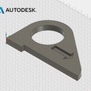
6) First click on the origin, then two more points, and then back to the origin to create a right triangle. The dimensions do not matter right now. The triangle will fill in with a light pink color once it is closed.
In the Sketch Palette on the right, make sure Grid and Snap are checked. This will make your drawing more accurate.
Step 4:


Step 5: Add Dimensions
7) Right click on the screen, choose Sketch, and Click Create Dimensions.
Alternatively, use hotkey D.
8) Click the bottom leg of the triangle and drag down. Click to set the field for the dimension value, type 13, and hit Enter on the keyboard. The bottom leg is now 13".
9) Repeat this process to change the dimension of the vertical leg of the triangle to 10".
Step 6:


Step 7:


Step 8: Add Step on Bottom Leg
10) In the ribbon, choose Sketch>Line. Or type hotkey L.
11) Draw a short vertical line that snaps to the bottom leg of the triangle, and a horizontal line that snaps to the hypotenuse of the triangle, to create a "step" on the bottom edge of the triangle.
Step 9:


Step 10: Add Dimensions to Step
12) Type D to add dimensions to the line.
13) Click the origin and the bottom point of the new vertical line, and set the dimension to 2.5".
14) Set the dimension of the vertical line to 0.5".
Step 11:


