

Introduction: GPIOs + More Python


This lesson teaches you how to use the General Purpose Input/Outputs (GPIOs) on your Raspberry Pi to control an LED and read a button’s state. The circuit you build in this lesson will be used in the photo booth final project.
You will be introduced to these programming concepts:
- while loop
- for loop
- indentation
- reserved words
- functions
Follow along with the lesson to type out all the code examples. If you get stuck, you can find the code files attached to each step.
Step 1: GPIO Pins

The GPIO pins are what you connect sensors and actuators to. It's the way your Raspberry Pi senses and interacts with the world. There are 40 pins in total. Four of these supply power (3.3 volts and 5 volts) and eight of them supply ground (which is the same as 0 volts).
Power and Ground Pins
The Raspberry Pi can provide low voltage DC power from several of it's pins. It offers 5 volts and 3.3 volts. For this project, it does not matter which one you use.
GPIOs and Digital Signal
The pins labeled GPIO can be programmed to support different kinds of sensors and devices. In this lesson, you will be using two of these pins to control an LED (output) and one to read a switch (input), both using digital electrical signals. A digital signal is either at 0 volts or at the highest voltage the RPi can provide, which is 3.3v or 5v. In other words, it can only have two states (binary). These two states can be represented three different ways in programming and computing:
1) HIGH/LOW
2) 1/0
3) True/False
A word of caution: the pins are fragile, so be careful while handling the board and avoid touching the pins themselves. Never connect or disconnect anything from the pins while the Pi is powered.
Step 2: A Bit About Electronics
If you want your Raspberry Pi to have the ability to sense the world around and react to it, you will need to get comfortable with building circuits. This class will not dive deep into electrical concepts but instead, will define terms that you are directly applying. To learn more about electronics and core concepts around electricity I recommend you take the Electronics class by Randy Sarafan and Arduino class by Becky Stern.
What is a Circuit?
An electrical circuit is a closed path that electricity travels along, enabling events like turning on LEDs and spinning motors. Circuits can be composed of only three components or extremely complex with thousands of components on one circuit board.
Check out this simple circuit for starters:
You will be using all of these items along with the Raspberry Pi to build your final circuit. Let's take a look at each of these components do.
Power Source
An electrical circuit needs a power source to move electrons through it. This power source can come from the wall through an AC adapter, or a battery, an example of DC power. A battery has two terminals, between which electrons flow, creating electricity. These two terminals are called positive, marked with a "+" and negative side, marked by "-". To learn more about how electricity flows and how batteries work check out the Electricity lesson in Randofo's Electronics class.
LED
LED stands for Light Emitting Diode. When the right amount of voltage is applied to the leads, an LED produces light. You can find LEDs in all kinds of shapes and sizes. In this class, you'll use 10 mm LEDs. To light up, an LED needs to be positioned in a circuit in a particular way. The short lead goes towards the negative side of the battery marked with a "-" and the longer lead goes towards the positive side of a battery "+".

Switch
A switch is basically just a mechanism for making and breaking an electrical connection. In it's simplest form, it has two metal contacts that stay open until you push or press it closed. Once closed electricity can flow around a circuit or to parts of it depending on how the circuit is built.
Resistor
A resistor is a common component found in circuits that limits the amount of current that flows. In this circuit, a 220 ohm resistor is used to protect the LED from blowing out (LEDs tend to draw too much power on their own).

Breadboard
A breadboard is a tool used for quickly building and prototyping circuits. It is comprised of holes that provide a plug-and-play way of connecting electrical components. The connections are made by metal plates inside the board. Once you know which holes are connected to which, you can start plugging in components to make electrical connections. Here's how the holes of your breadboard are connected:

Notice the blue and red lines next to the long strips. These are called the power and ground bus strip or rail. Power and ground are jumped to these strips so components can easily access them.
Step 3: A Circuit With Endless Possibilities

When the switch is pressed in the above circuit, the LED immediately receives power and goes on. It's very exciting but what if you wanted to change the behavior of that LED such as when it turns on? Or, what if you wanted the LED to blink 3 times and then turn off? You need some kind of electronic brain to help. That’s where the Raspberry Pi comes in.
The LED then becomes an output that the Raspberry Pi can send power to whenever you tell it to. Similarly, a switch becomes an input and the event of closing (and opening!) a switch can be read by the Raspberry Pi and used to trigger events. In other words, the Raspberry Pi gives you the ability to change a circuit's behavior quickly and easily through writing and running programs which you will be doing using Python. This way you don't have just one outcome but thousands of possible outcomes without changing the circuit itself.
Step 4: RPi.GPIO Python Module
Python is a great way to program the GPIO pins on a Raspberry Pi. To talk to the GPIO pins using Python, you will reference a module called RPi.GPIO. Most of the time you will need to install new modules. However, since this module is so widely used, it comes bundled with Raspbian.
Modules add tools to your toolbox you never thought you had the time to learn before. New modules are being written all the time. To start finding Python modules type "fun Python modules" or "best Python modules" into a search engine and see what pops up.
If for some reason you are unsure about whether your Raspberry Pi has the module installed, there is an easy way to check using Python. Open the Python 3 shell and type:
import RPi.GPIO as GPIO
Hit enter and if another prompt prints on the next line this means that it’s installed and Python is ready for the next instruction. If Python errors and tells you that the module can not be found this means you need to install it. Open a terminal window and download the Python 2 and Python 3 version of the module.
sudo apt-get update

sudo apt-get install python-RPi.gpio python3-RPi.gpio
* There really is a Python module that can track planets, it's called PyEphem.
Step 5: Build Circuit

Time to get to circuit building! Connect the LED and a 220 ohm resistor (red, red, brown) to your Raspberry Pi as shown in the diagram. Jump ground from the Raspberry Pi to the ground rail on your solderless breadboard, and jump GPIO 17 to the positive side of your LED-resistor combo.
Positive (long) lead of LED --> 220 resistor
220 resistor --> GPIO pin 17 (board pin 11)
Negative (short) lead of LED --> Ground rail
Ground rail --> board ground pin


Step 6: Blink an LED
Ready to make some LEDs blink? Open the Python 3 shell and follow along.
The first thing to do is to tell Python to import the RPi.GPIO module so you can use it.
import RPi.GPIO as GPIO
Next, tell Python which numbering system you are going to use to reference the pins on the Raspberry Pi board, BCM or BOARD. You can find these two numbering systems illustrated in the diagram from the GPIO Pins section above.
- GPIO.BOARD – These pin numbers match the board's numbering scheme which is in numerical order from left to right and from top to bottom.
- GPIO.BCM – Broadcom chip-specific pin numbers. These pin numbers follow the lower-level numbering system defined by the Raspberry Pi’s Broadcom-chip brain.
I tend to use the BCM numbering system. You can use either one as long as you stick to it throughout your program. To set the numbering scheme use GPIO.setmode():
GPIO.setmode(GPIO.BCM)
Create a variable to hold the pin number the LED is attached to:
yellowLed = 17
A pin needs to be set as an output or an input. The LED pin is being used as an output:
GPIO.setup(yellowLed, GPIO.OUT)
A digital output, like the LED, can either be on or off. The on state can be written as 1, GPIO.HIGH, or True. Use either one in your program and make sure try all three. I will use True:
GPIO.output(yellowLed, True)
The LED will turn on! If it doesn't, double check your wires are connected to the right pins on the Pi and that your LED is in the correct orientation. The off state can be written as: 0, GPIO.LOW, or False. Turn the LED off:
GPIO.output(yellowLed, False)
Use GPIO.cleanup() to clean up the pin channels that you use to free them up to use next time.
GPIO.cleanup()

Keywords/Reserved Words
Notice the words import, as, from, and True turn a color when you type them in Python. This is because these are all keywords which are reserved words in Python. Keywords can not be used to name variables, to define functions or for anything else besides what they are reserved to do.
Step 7: Infinite Blink With While Loop
Move to an editor so you can save and edit your program. Open a new file (Ctrl + N) in the editor of your choice (IDLE, Leafpad, or Nano) and save it as blink.py. The goal of the following program will be to continuously blink the LED on and off. Start by adding the following lines to your program:
import RPi.GPIO as GPIO # import GPIO library
from time import sleep # import time library
GPIO.setmode(GPIO.BCM) # set pin numbering system
yellowLed = 17 # variable holds LED pin number
GPIO.setup(yellowLed, GPIO.OUT) # set the pin as an output or input
There are a couple new things in the above lines of code. A pre-installed module called time is imported so a delay (pause) can be added to the program, and comments are added.
Comments
The "#" character comments out anything that is to the right of it, meaning Python will ignore it. Comments are used to make notes in a program. I will be using them from now on as reminders of what each line is doing.
So far, you have written programs that run in sequential order, from top to bottom, then stop. If an LED is to blink continuously, do you need to write infinite lines of code? Thankfully, not! In programming, that’s what loops are for.
To make the LED continue to blink you will use a while loop. The while loop repeats a block of code as long as a specified condition is true.
While loop syntax:
while <condition>:
	<code>
will change when written out in a program. The while does not change; it is a reserved word.
If the <condition> is True, the <code> in the loop will execute. If the condition is False, it will ignore the code in the loop.
To create an infinite loop you can make the condition always true. So, where is the loop and how does Python know which code is in this loop? It knows because of two things:
1) the colon after the condition
2)indentation of the lines underneath
Making sure that your code is indented properly is very important in Python. Some languages use curly brackets to identify code within loops and functions, Python uses indentation.
Put It To Use
Add these new lines to your blink.py program, save, and run the program. The LED will start blinking on and off every second.
while True:
	GPIO.output(yellowLed, True)
	sleep(1)
	GPIO.output(yellowLed, False)
	sleep(1)
The sleep() function takes one numeric argument: a number of seconds. Change the 1 argument passed in the sleep() function to change the timing of the on and off states.

This program will blink into infinity until you manually stop the program from running. To stop the program in IDLE, restart the shell through the toolbar or Ctrl + F6. In LXTerminal press Ctrl + Z.

Step 8: For Loop
Instead of getting stuck in an infinite loop of LED blinking, you can give the LED a finite number of times to blink using an iterative for loop. The for loop is used when you want a piece of code to be repeated n number of times.
For loop syntax:
for <variable> in <sequence>:
	<code>
Let's look at the parts of a for loop a little closer.
You can call the variable in the for loop (almost) anything you like, but you will usually see it called “i” for index.
The sequence is the data the variable iterates through one item at a time. This data can be numbers or words that are presented in list form.
The code is what will repeat as long as there are still items in the sequence.
To try the for loop out, you first need to make a list of data for it to iterate through. The for loop will step through the sequence one item at a time. For example, if you have five items in the sequence the code will be looped five times. The sequence is where you will express how many times you want to blink your LED. To make a list of numbers in Python close them in brackets and separate with commas like this:
[0,1,2,3,4]
To store the sequence in computer memory, we should put the list into a variable.
blinkTimes = [0,1,2,3,4]
Put It To Use
Let's use it! Make a new file and save it as blinkFor.py. Put the following code into your file:
import RPi.GPIO as GPIO #import GPIO library
from time import sleep #import time module
GPIO.setmode(GPIO.BCM) #set pin numbering system

yellowLed = 17 #put pin connected to the yellow LED in variable
blinkTimes = [0,1,2,3,4] #create list and put it in a variable

GPIO.setup(yellowLed, GPIO.OUT) #set the LED pin as output

#iterate through list held in blinkTimes variable
for i in blinkTimes:
	#blink LED
    	GPIO.output(yellowLed, True)
    	sleep(1)
    	GPIO.output(yellowLed, False)
    	sleep(1)
Save and run. The LED will blink on for 1 second and off for one second five times! Experiment and alter the program so the LED blinks six or ten times.
Range()
In programming, there is always more than one way to do something. Instead of creating a list and putting it in a variable, Python has a built-in function that already does this called range().
You can pass range() one numeric argument that will generate a list for you. For example:
range(5)
Is the same as:
[0,1,2,3,4]
Put It To Use
Try it out by deleting the blinkTimes variable and list at the top and replacing blinkTimes with range(5) for the sequence in the for loop:
for i in range(5):
	GPIO.output(yellowLed, True)
	sleep(1)
	GPIO.output(yellowLed, False)
	sleep(1)
Attachments
Step 9: Build Circuit

It is likely you will want to put many LEDs in a project, and need another anyway for the photo booth project. Connect a second LED as shown in the diagram.
Positive (long) lead of LED --> 220 ohm resistor
220 ohm resistor --> GPIO pin 27 (board pin 13)
Negative (short) lead of LED --> Ground rail
This circuit will be part of the final photo booth project, so let's figure out how we want them to behave. In the final photo booth project, there are two LEDs. One alerts to you to get ready to smile before the camera starts snapping photos. Let's call this the countdown LED. The second LED turns on when the GIF has been uploaded to the internet. Let's call it the upload LED. Choose a different color of each. I chose the yellow for the countdown LED and blue for the upload.

Step 10: Blink Two LEDs
To get the second LED blinking add another variable below yellowLED = 17 and call it something unique:
blueLed = 27
Set the pin as an output:
GPIO.setup(blueLed, GPIO.OUT)
Create a for loop for the LED and put it below the first one. Change the number of times it blinks and how long the delay is. This blinks the blue LED three times every three seconds:
for i in range(3):
	GPIO.output(blueLed, True)
	sleep(3)
	GPIO.output(blueLed, False)
	sleep(3)
Save this sketch as twoLEDs.py and run. The first LED will blink then the second!
Great! You now have your two final LEDs for the photo booth working! Change the behavior of the LEDs to fit their purposes better. For example, perhaps you don't want your upload LED to blink at all and want it to stay on for a whole 10 seconds to make sure people see that the photo has uploaded. Or, you want the countdown LED to blink 3 times for a 3, 2, 1 countdown.
As an example, I made my countdown LED blink at two speeds. The first is a steady blink and then comes a second faster speed to get the blood pumping and to say "Hurry and get ready for your photo!". I added this second yellow LED loop below the first one:
for i in range(5):
	GPIO.output(yellowLed, True)
	sleep(.25)
	GPIO.output(yellowLed, False)
	sleep (.25)
Save and run to see the final blink sequence used for the photo booth. Experiment with your own timing and patterns; customizing it is what it's all about!

Attachments
Step 11: Build Switch Circuit

Time to read a switch! First, you need to connect jumper wires to the switch's leads so you can connect it to the Raspberry Pi. The leads on this switch are the two bottom screw terminals.
Grab two jumper wires and a pair of angled wire cutters. Make sure the jumper wires each have a female header at one end. Cut off the end opposite the female header and strip the insulation off about 1/2" down.
Use a small Phillips head screwdriver to loosen the two lower terminals on the switch. The goal is to wrap the wire around the screw and to then capture it between the metal plates by tightening the screw. It helps to first twist the small strands of the wire together then create a small hook with the wire to hook around the screw post (clockwise, so the screw tightens the wire around the screw). Once your wires are connected to the switch, connect the switch to the Raspberry Pi as shown in the diagram:
either side of switch --> GPIO 18 (board pin 12)
remaining side of switch --> power pin (either 5 volts or 3.3 volts)
Leave the LEDs plugged in the breadboard; you will use them later on.

Step 12: Read Switch State
Rather than sending a signal out to an LED you will now have the Raspberry Pi read a signal coming in. In the following program, you will use the Raspberry Pi to read whether the switch is open or closed.
Open a new file and save it as button.py. Add the following lines of code to your program:
import RPi.GPIO as GPIO
Set the pin numbering system and create a variable for the pin the switch is connected to:
GPIO.setmode(GPIO.BCM)
button = 18
Set the pin as an input:
GPIO.setup(button, GPIO.IN)
In a while loop, read the switch's using GPIO.input() and store it in a variable. Once you store the state, check to see if it equals True (1, HIGH) or False (0, LOW). You do this by using an if statement. Make sure the if statement is under the while loop:
while True:
	input_state = GPIO.input(button)
	if input_state == True:
		print(“button pressed”)

GPIO.cleanup()
If the switch state does equal == True, the code within the if statement executes. The code within the above if statement is a simple print of the phrase "button pressed".
Save and run.
Step 13: Pull-down and Pull-up Resistor
Press the switch and see if anything happens. If a "button pressed" isn't already there it will pop up. Do you notice anything about the behavior of the switch and the prints in the shell? It's hard to actually see a relationship between your press and when it prints "button pressed". Your goal is to only print when the switch is closed. What's going on?
This is happening because what you have is a floating pin. When the switch is closed, the switch connects the pin to power is referenced which is why you get a 1, True or HIGH. When the switch is open, the pin doesn't know what to reference because it's not connected to ground or power. So, how do we give it a reference? The answer is a pull-up or pull-down resistor, which provides a reference to power or ground when the pin would otherwise be floating.
This pull-up or pull-down resistor can be added to your circuit as an extra component. Or, you can enable one through software, which is what we will do. To enable a pull-down resistor using the GPIO library add an argument to your setup line:
GPIO.setup(button, GPIO.IN, pull_up_down=GPIO.PUD_DOWN)
Run the program again and you will get a "button pressed" only when you actually press the button. But it prints many, many instances of “button pressed”.

This is because of another phenomenon that happens often when reading switches. What's happening is the button can create and break an electrical connection many times as you press it once. This is called bouncing. A delay can help you with this by pausing the program for a short time to wait for the bouncing to stop. Give the button some time to open completely before it goes through the loop again using sleep(). Add the delay after the print() statement.
while True:
	input_state = GPIO.input(button)
	if input_state == True:
		print(“button pressed”)
		sleep(.4)
Save and run. "button pressed" will now only print once when the button is pressed.
Step 14: Combine Input and Output
So far, you have learned how to blink an LED and read a switch. Now, let's get one affecting the other. Conveniently all the components are already connected and ready to go, so let's write some code.
The goal is to make the LEDs go through their flash routine once the button is pressed. Remember that if statement? Simply replace the:
print ("button pressed")with the blink sequence.
What follows is the full script to begin the blink sequence when the button is pressed (save it in a file called button_LED.py):
import RPi.GPIO as GPIO
from time import sleep

yellowLed = 17
blueLed = 27
button = 18

GPIO.setmode(GPIO.BCM)
GPIO.setup(yellowLed, GPIO.OUT)
GPIO.setup(blueLed, GPIO.OUT)
GPIO.setup(button, GPIO.IN, pull_up_down=GPIO.PUD_DOWN)
while True:
    input_state = GPIO.input(button)
    if input_state == True:
        for i in range(5):
            GPIO.output(yellowLed, True)
            sleep(1)
            GPIO.output(yellowLed, False)
            sleep(1)
        for i in range(5):
            GPIO.output(yellowLed, True)
            sleep(.25)
            GPIO.output(yellowLed, False)
            sleep(.25)
        for i in range(3):
            GPIO.output(blueLed, True)
            sleep(3)
            GPIO.output(blueLed, False)
            sleep(3)

GPIO.cleanup()
Attachments
Step 15: Combine With Camera!
Whew! Great job. You've done a lot with just one simple circuit. Now, let's add the camera module. Instead of using Raspistill to take a photo like you did previously in command-line, you will use a Python module called picamera.
Create and save a new file called button_LEDphoto.py. Write the following code:
import RPi.GPIO as GPIO
from time import sleep
import picamera

yellowLed = 17
blueLed = 27
button = 18

GPIO.setmode(GPIO.BCM)
GPIO.setup(button, GPIO.IN, pull_up_down=GPIO.PUD_DOWN)
GPIO.setup(yellowLed, GPIO.OUT)
GPIO.setup(blueLed, GPIO.OUT

camera = picamera.PiCamera()
camera.resolution = (640, 480)
camera.brightness = 60
try:
    while True:
        input_state = GPIO.input(button)
        if input_state == True:
            print("button pressed")
            sleep(0.4)

            for i in range(3):
                GPIO.output(yellowLed, True)
                sleep(1)
                GPIO.output(yellowLed, False)
                sleep(1)
            for i in range(3):
                GPIO.output(yellowLed, True)
                sleep(.25)
                GPIO.output(yellowLed, False)
                sleep(.25)

            camera.start_preview()
            sleep(2)
            camera.capture('testImage.jpg')
            camera.stop_preview()
            camera.close()

            for i in range(3):
                GPIO.output(blueLed, True)
                sleep(3)
                GPIO.output(blueLed, False)
                sleep(3)
    GPIO.cleanup()
except KeyboardInterrupt:
    print ('program stopped')
Save and run. The countdown LED will do its thing, then the camera will snap a photo.
After the image preview has stopped, the upload LED will go on. But right now, this program doesn’t upload anything! That's what the next lesson will teach you. Let's give that LED a real reason to go on!
Attachments
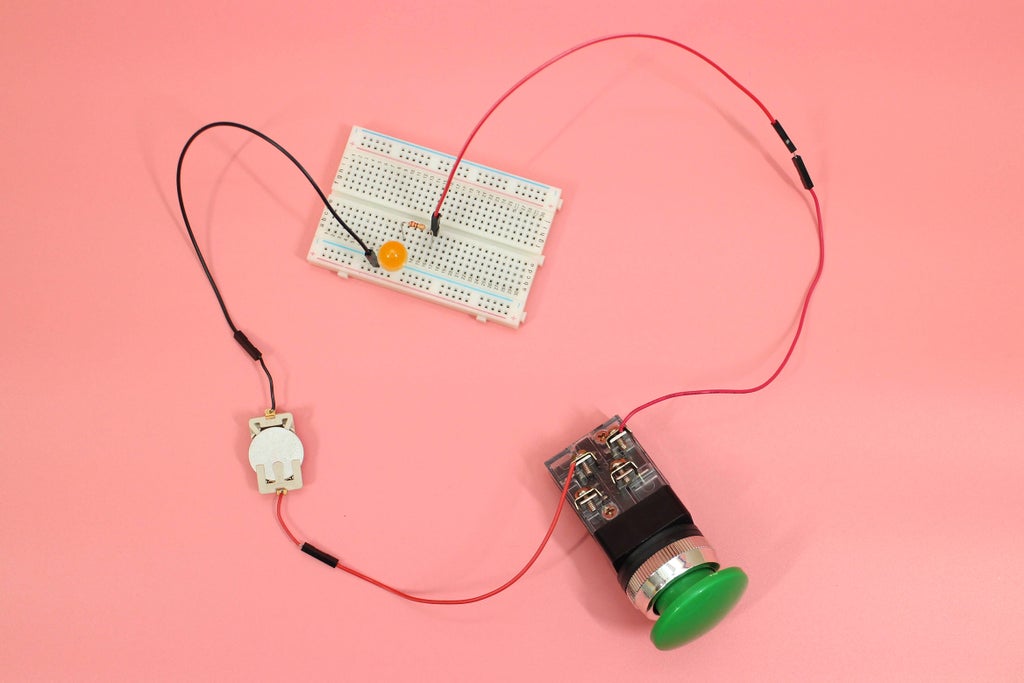
Step 16: Upload Photo of Circuit
Upload a photo of your final circuit using two LEDs and one switch.

![Tim's Mechanical Spider Leg [LU9685-20CU]](https://content.instructables.com/FFB/5R4I/LVKZ6G6R/FFB5R4ILVKZ6G6R.png?auto=webp&crop=1.2%3A1&frame=1&width=306)


