

Introduction: Digital Geneva Clock


More by the author:


About: I am interested in designing something curious but functional. Please take a look at my summary page, https://shiura.com/dfab/index-en.html
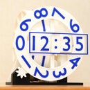
A simple digital clock with sequential Geneva drives.
- Easy time adjustment using sliding mechanism to release the engagement of Geneva drives
- Easy to make with only 9 printed parts
- Driven by a single motor
- Easy to print without support structure
- Ready for small printers : All parts can be arranged within 160 x 160mm build table
Supplies

- 28BYJ-48 geared stepper motor and driver board comes with
- Any microcontroller (Arduino, ESP32, Raspberry Pi, etc.)
- Assortment of 2mm tapping screws
Step 1: Print

- Print all parts with supplied posture.
- Support structure is not needed.
- Remove debris and blobs well, especially around the axes and sliding surfaces.
- Use the material in different color for "10min-slider" and "10min-axis" for better digit visibility.
Attachments


Step 2: Assemble


- Assemble hour unit with "hour-weel", "hour-slider" and "hour-axis-cap" with a 2mm tapping screw.
- Assemble 10min unit with "10min-weel", "10min-slider" and "10min-axis" with a 2mm tapping screw. The direction of the 10min-axis is regulated by the trapezoid-shaped hole.
- Attach the motor to the frame. Then insert the 1min-wheel to the motor axis. Please make sure that the 1min-wheel is not tilted. 1min-wheel should be at very close to the top surface of the frame.
- Insert two units to the frame then attach a rubber band to the screws on the back of the slider.
Step 3: Circuitry

- Use your favorite microcontroller to drive the stepper motor.
- The program ("clock.ino") below is a sample for Arduino. If you use other microcontrollers, drive the motor 2048 steps per 10 minutes.
- Housing of the arduino nano and driver board can be found at https://www.thingiverse.com/thing:5145523
- There is some space in the frame. You could hide circuitry in the frame if you use small micro controller.
If the motor rotates to the opposite direction, change the source code,
from
int port[4] = {7, 6, 5, 4};
to
int port[4] = {4, 5, 6, 7};
1sec.ino below is the code for test and demonstrations (the motor runs every second).
Please download the program for Arduino ("clock.ino" and/or "1sec.ino") below.

Step 4: Time Adjustment

- Hour and 10min wheels can be rotated by your hand.
- The program for Arduino drives the motor immediately after reset. Therefore, You can proceed 1 minute by reset button .
- Alignment of the 1min rotor can be also possible by the reset button. Press the reset button when the digit comes to the correct position.
- Manual rotation of the 1 min rotor is also possible because the current to the motor is shut down when it does not run.
Step 5: Tuning of the Clock Speed

The clock of Arduino is not as accurate as common clocks. Please tune the value to improve the accuracy of your clock.
- Measure the error of your clock. Adjust your clock correctly and wait for 24 hours, then Measure the error of your clock in seconds.
- Input the error value (in second) for the value named COMPENSATION_SECONDS at line #3 in the source code. If your clock gains (too fast), enter positive value, and vise versa.
- Compile and flash your program to your microcontroller.


![Tim's Mechanical Spider Leg [LU9685-20CU]](https://content.instructables.com/FFB/5R4I/LVKZ6G6R/FFB5R4ILVKZ6G6R.png?auto=webp&crop=1.2%3A1&frame=1&width=306)


