

Introduction: Full Color LED Cyber Suit! (additional Instructables for NES Powerglove Control, Live Audio EQ,etc.. to Follow!)


I just couldn't resist creating an instructable for a "Make it Glow" contest. And if your gonna make something glow, it might as well be yourself! In this instructable I'll take you through all the steps for building your own glowing LED cyber suit, however....My goal is to give you the information needed to allow you to create your own version of a LED suit (or LED wearable of any kind), and not be limited to my particular style or concept. I have learned a lot over the past couple years of making LED wearables and hopefully I can pass on some of lessons I had to learn the hard way and save you a lot of time and frustration.
Since a lot of people who express interest in making an LED wearables often have little or no experience with LEDs, micro-controllers, or electronics in general, my goal with this Instructable is to also provide a comprehensive "crash course" on the subject suitable for the absolute beginner. For those who have experimented with LED strips and arduinos, some of this Instructable may contain a lot of information you already know so I will try to add links throughout that skip through some of the novice related information.
I'll be adding a set of additional instructables to go over how to add and integrate additional hardware to the suit like real time audio analysis and spectrum analyzing, NES Powerglove suit control, and using acceleromters and gyroscopes to give some unique forms of control to your new suit. Here's a couple videos showing different phases of the suit and some of the different hardware integration's.
Helmet Animations:
Manual LED manipulation via hacked NES PowerGlove:
Real Time Spectrum Analyzer via suit mic (or line in from any audio device):
Let's start with an overview of the electronics and materials well be using
Step 1: Overview and Options - Suit Materials and Items


Because there are many MANY different ways to skin this cat, lets start going over some of the options for suit materials, LED choices, and a brief overview of how the LEDs and electronics are controlled.
Suit Clothing and Accessories
Whether you want to make an entire LED suit or just a single LED wearable item, your going to want to start with some type of base item to mount your LEDs and gadgets onto. This can be as simple as a pair of sun glasses, or elaborate as a full set of body armor. Although any item can be decked out in LEDs, each item and type of material will have it's own unique quirks and difficulty levels. Here's a good example of two items with similar appearance but each required very different construction methods and build times.
1. Padded Mesh shirt by Empire Paint Ball:
I was initially attracted to this shirt because of the nice geometrical shapes and it's somewhat futuristic armor style. Considering I wear these suits mainly at music festivals which can often be outside in scorching hot weather, I was also very attracted to the fact that it was extremely light and made of breathable mesh. This later proved to be a very problematic choice that caused hours of frustration.
The flexibility in this shirt created a ton of areas that where easily damaged from just normal use, and we won't even get into the problems that can occur wearing a suit like this in the middle of a highly energetic concert crowd. Although most LED strips come on flexible PCB's they aren't really intended for hard creases or constant bending. (There are some new LED strips where this issue much less of a concern, but more on that later)
2. Hard shell protective vest
The second version of this suit I made used a hard shell vest for the top. There ended up being a few reasons this worked MUCH better then the first top. Firstly, the harder surface made it MUCH easier to mount and wire up the individual LED sections. Because of it's sturdiness the LEDs really didn't flex hardly at all when being worn. This drastically reduced the likely hood of a strip getting damaged. The third big improvement using this type of vest was in the overall design and the way it's intended to be taken on and off. The first top had to be put on delicately and over my head just like any other shirt. This vest allowed the straps across each side to be un-clipped and easily pulled right off over your head. Again, much less potential for damage to the strips and a lot quicker time getting in and out of the suit.
I'm not saying that one option is really better then the other. You just need to realize there are differences between each type of material and item you chose to include in the suit. If this is your first time creating an LED wearable I would suggest starting with a suit item that has a more rigid surface. Helmets and Knee pads are excellent starter items.
Step 2: Overview and Options - LEDs

For those who aren't familiar with the different type of LED strips available let's go through a quick "Intro to LED strips" crash course.
When it comes to LED strips, there are really three main types that you will want to choose from. Each of these types of LED Strips have pros and cons and the decision will just have to based on your own comfort level, budget, and desired features you want in your suit. Regardless of the type of strip you choose, there will be additional options found on most all strips like LED spacing and waterproofing. We'll also cover these options below.
LED Types
2. RGB LED strip (non-addressable):
Each LED on a RGB strip actually consist of one Red, one Blue, and one Green LED. An RGB LED will have a positive power lead for each of these individual colors and they will all share the same ground. You can power each one of these colors individually, together, or by mixing different levels of voltage to each led to create any combination of colors.
3. RGB addressable strip:
So you've decided to put on your big boy pants and go for the ultimate in LED's. RGB addressable strips are with out a doubt the greatest thing in the world of blinkyness at the moment. On an RGB addressable strip every LED can be any color, at anytime, and all are controlled individually. They are often referred to as "Smart" strips or LED Pixels. The color of each LED is set by communicating with a set of chips on the strips using a microcontroller.
(To the newbie's.. Not knowing anything about programming or microcontrollers is NO excuse no to use addressable strips. I PROMISE you that you can do it, and if you just follow the steps in this instructable you will be up and running in no time)
**IMPORTANT information about Pixel Strips**
If your looking for strips to purchase it's important that you know that are A LOT of different types of Pixel strips. For the sake of this Instructable I'm going to be using the WS2812 LEDs, these are also called "Neo-Pixels" on the adafruit website. These pixels are def the best option available right now, especially for a wearable. The Neo-pixels have a unique aspect about them that makes them different from all the rest. The individual chips that control each LED's color is actually INSIDE the LED itself. I know....it's pretty amazing.
The minimized amount of electronics on these strips almost drastically decreases the likely hood of a faulty strip due to the stress of a wearable item. TRUST ME! Use these strips if at all possible.
NeoPixels from Adafruit.com
LED Spacing (Applies to all types)
Most LED flex strips can be purchased with various numbers of LED's per meter. This is another one of those options that can make a big difference in the final outcome of your project as well as the difficulty required for construction. There is typically 3 main spacing options used on LED flex strips.
60 per meter
144 per meter
Which spacing is the best really depends on the application but there are three main factors to consider when making this decision:
Some items and LED layouts will just look better with different spacing layouts then others
2. Power
This is a BIG factor regardless of the strip type you choose. The more LED's per meter, the more power your going to need. Keep in mind that a suit item with 3 meters of 144 LED's per meter is going to need almost 4x the amount of power then on using 3 meters of the 30 per meter strips.
3. CPU Power
This really only applies if you have chosen to use RGB addressable LED's. Each addressable LED requires a specific amount of memory as well some computing power if you are using code to compute the individual LED color. The next step will talk specifically about controller options but for now just realize this is a factor when planing your suit.
LED Strip Waterproofing (Applies to all types)
Another rather important option is whether or not to get strips with weather proofing. There are 4 general waterproofing options available, again each one having its pros and cons.
Go this route if the item your making will be used only indoors, and around NO liquid. (Keep in mind an LED suit gets hot, which means you will most likely sweat, which means you probably don't want this option)
2. Silicon covered PCB
This option is excellent ONLY IF you are not going to be cutting the strips into smaller segments. These strips do a good job of keeping out water but they also make it a huge pain to cut back the silicon to get to the points needed to solder segments together.
3. Plastic flexible casing surrounding strip
I won't say I'm completely against this type of water proofing, but I'm pretty much completely against this type of water proofing. Again this only worth looking into if you are not going to be cutting the strips into multiple sections. If the strips your wanting to purchase only come with this outer plastic casing, it is very easy to cut and remove (unlike the silicon).
4. Bare Flexible PCB and cans of the magical NeverWet.
This is now my overall preferred method. I have put NeverWet through some pretty serious test with my suits and I'm a believer!)
LED Strip Voltage
Strips typically come in 5V or 12V versions. I personally do not use any 12V strips. Most micro controllers can supply some amount of 5V and it's pretty easy to wire up some double A's to get 5v to the strips.
Whew! That about sums up our LED Strip 101 crash course. You should have most of the information needed now to make a decision on what type of strips or combination of strip types you want to use. Now we can take a look at the controller options.
Step 3: Overview and Options - Controllers for Dumb Strips


I'm going to spend the majority of the this Instructable based on a suit of "smart pixels" but most of the construction process will be the same regardless of the type of strips your using. There are a couple controller options specifically for the dumb LED strips that I'll briefly mention.
For the single color strips you can use any standard On/Off toggle switch but there is another option that will add a little more 'flare' to your suit:
1. Single Color Dumb strip Dimming controller: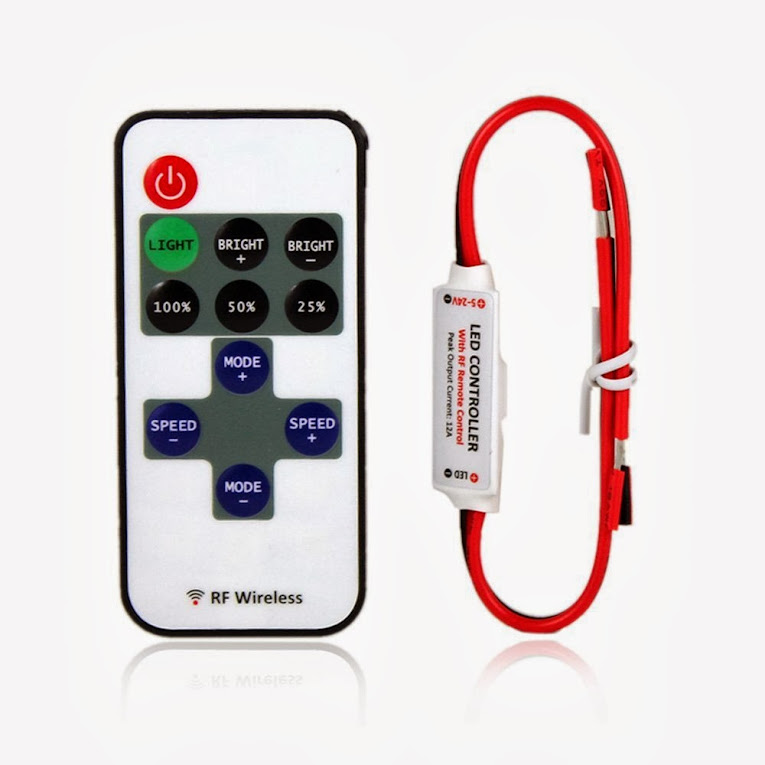 This is a much better option then an On/Off switch. This little device will let you turn your strips on and off, as well as dim the strips to any level of brightness. It comes with a wireless remote so you can easily hide the controller inside the suit item set the LED level with the push of a button.
Single Color controller on Amazon - $6
We'll go over wiring this controller in a later step
1. RGB Dumb strip Manual Controller: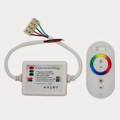 Like the single color controller except this module will let you wireless turn your RGB strip on and off as well as manually select specific colors. Another nice feature on most these controllers is that they can cycle through colors on their own allowing you to set the mode/speed and put the controller in your pocket the rest of the night. Your not going to want to mess with a controller during all those pictures people are going to want to take with you :)
RGB Controller on Amazon
We'll go over wiring this in a later step
Step 4: Overview and Options - Controllers for Pixel Strips

For "Smart" pixel strips your going to need an actual micro-controller. I've used a lot of different micro-controllers and when it comes to LED wearables there are two controllers that are my "go-to" boards. You can most certainly use any micro-controller that supports the type of pixel strips your using, but in my opinion, the two below are are going to give you the most 'bang for your buck'
1. Adafruit Trinket / $7:![]() Use this if you are controlling less then 150 Smart pixels
Use this if you are controlling less then 150 Smart pixels
The trinket is really an amazing little controller. Its the smallest I've come across, which is a huge factor in an LED Wearable, and it's extremely affordable. There are very few IO pins available (5), so you are going to be limited on the type of control devices you can use but for a basic wearable with some switches, or just canned animations, this is a perfect fit.
2. Teensy 3.0 - 3.1 / $17 - $21: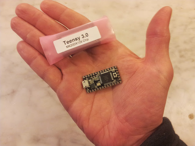 Everyone else use this.
This micro-controller is my absolute favorite and I can't imagine a full suit build with any other micro. Why do I love the teensy?
A. Size
It's pretty darn tiny. Just slightly bigger then the teensy.
B. Performance
The. teensy 3.0 can drive 1000+ smart pixels, and the 3.1 can drive 4000+. For those that are not familiar with the limits of smart pixels connected to a microcontroller these limits are pretty insane. Nothing in its price range even comes close.
C. PINS PINS PINS PINS
For a micro this size there are SO many pins for connecting additonal hardware to. Considering the way this micro drives the smart pixels using DMA and requires almost 0 processor power, theres plenty of power to handle the additional hardware.
I'll stop with those main points, but I could go on and on about the teesny boards.
Just go buy one...NOW.....GO!
Step 5: Overview and Options - Power

Powering your suit can be one of the biggest challenges of the whole project. If your making a single item, or an item with just a few LEDs, you can probably get by with AA pack of three AA's. or even less depending on the size. For each of the suits shown in this Instructable I use two of the D battery packs that hold 3 D's per pack. This is enough to power the suits for about 8 hours of continuous animations.
I could go into a lot of detail about different types of batteries and methods for Powering them, but the folks at Adafruit have a much comprehensive guide to LED Pixel power then this Instructable could go into. I suggest taking a quick look over Pixel Power Uber Guide to help select the best power supply for your project.
For now, a AA or D battery holder that hold 3 batteries will work just fine for all our testing and build processes. Our design will allow for easy swapping and adding of additional power supplies if needed later on.
D Battery holder on amazon
AA battery holder on amazon
Step 6: Final Prep - Materials and Tools


Required Items:
Your choice of LED's
Your choice of item/clothing to attach LEDs to
Your choice of controller (on/off, pots, micro-controller)
Required Tools and Materials:
- -Soldering Iron - (If your doing a full suit, go ahead and get you a decent one if you don't already have one)
I LOVE this iron
- Solder and LOTS of it
- Hot Glue gun
- Hot Glue ( Hot glue for fabrics if your putting LEDs on cloth material)
- Stranded Wire ( Everything from cat5 to 22 guage will work)
- Battery pack (Double A packs for smaller items, D packs for larger setups)
- Wire cutters
- Helping Hands
- 4-Pin JST connectors from adafruit
Your going to need two pair of connectors for each suit item, two pair for each battery pack, and atleast 2 additional pair. (go ahead and grab a few extra. They come in handy!)
Optional Items (Highly Recommended )
- Black Hot Glue - This should probably be in the required section as it's, by far, the most beneficial item I have ever come across for suit builds and I'll talk more about this in later steps. It's definitely possible to build with out it, but just go buy some. You absolutely WILL NOT regret it.
- Elastic Fabric (for making 'strap on' battery packs)
- Large 2" Velcro strips - (for strap on packs as well)
- Small standard velcro strips (for mounting various components)
Step 7: Final Prep - Electronics Placement

The last step before we actually start powering on LEDS and building our suit is to get a rough idea of where the LEDs and various electronics will be mounted. Like a lot of aspects of this project, this will be different for every project. The LED strip layout is pretty much up to your own artistic style and creativity.
What you want to primarily look for right now is a good location for your strip controller and battery packs. On the suits show in this Instructable leg holster straps where attached to the suit pants legs. Each leg holds one of the D battery packs. I recommend something similar if your using large packs. Leg holster, waist belts with packs off the hips, or thin packs on the back of a sturdy vest all make good locations. A velcro pouch can easily be made onto any part of the suit to hold the tiny micro controller.
Well go over all this in later steps but for now make sure you start to think about the general location all the strip wiring will eventually go to.
Step 8: LED Strip Test - Dumb Strips

The first thing I always do on a new Item build is make sure the electronic components are working before I start actually building anything. Depending on the type of strips the testing process will be slightly different. Let's start with just a basic test of the dumb strips.
If you have a single color or rgb dumb strip the testing process is pretty simple. For this test your just going to need your LED strips and a 5V power supply (or 12v if you decided to use a 12v strip). If you don't have a dedicated 5V supply, you can get close enough to 5v using a battery back of 3 double A batteries or 3 D batteries. (You can use a pack that holds 4 batteries but some LED strips are very sensitive to anything over 5v so I try to never use these with out a power regulator on my strip).
To test a single color strip, simply apply the positive lead from your batteries to the V+ on your strips, and the negative lead to the Ground on your strips. That's it. You should now have power to all your lights. If no lights come on, make sure your leads aren't reversed from the power supply and that you are getting enough voltage from the power supply.
For an RGB Dumb strip your going to test them almost the same way as above, except on the RGB strip you will have 3 V+ leads (one for each single color led in an RGB). To test connect the negative lead from your power supply to the Gnd on your strips and then connect the V+ to one of the three remaining leads on the strip. You should see your entire strip light up with either Red, Blue, or Green. If you switch the V+ to another one of the leads you should get one of the other colors. Test all three V+ leads on the RGB strip to make sure everything appears to be working and you don't have any bad LEDs.
Step 9: Smart Pixel Strip Test - Attach JST Connector to Strip


Time to finally see these strips in action!
In order to test these strips we need to do a little initial preparation of the strips and our controller. We're going to go ahead and solder some of the JST plugs onto our controller and to the strip itself. We will use these JST connector through various parts of the suit to make to wiring process much much simpler.
Start by getting your LED strip and locating the end that came with the a set of leads already attached. (If your strip has no leads attached then we'll be soldering right onto the leads on the strip themselves.
** Note: if your using the suggested Neo-pixels you will only have three wires to connect to. The previous types of strips required 4 wires and I've yet to find a good source of 3-wire JST connector so we'll just use the 4 wire connectors and have an additional lead
Solder your a female JST connector to the led following the first diagram image in this step. Make sure your attaching the plug to the input end of the strip.
Step 10: Smart Pixel Strip Test - Attach JST Connector to Micro-controller

Now let's add a Male JST plug to our Micro-controller. You can either solder this directly onto the board or attach header pins to the board and solder your jst plug to a set of female header wires. The diagram included in this is of the Teensy controller. Use the V+, Gnd, and D1 pin of the trinket in the same way as the teensy image illustrates.
Step 11: Smart Pixel Strip Test - Preparing Micro for Strip Control

This step is going to get the needed code onto our microcontroller and run a test sketch that should give us some basic animations along out strip.
Leave the strip disconnected from the micro-controller for the moment and plug your controller into your computer. Assuming your using the Neo-Pixels your going to need to download and add the "NeoPixel" library to your arduino enviroment. If you're using a strip other then the neo-pixels your going to need to locate the appropriate library and do the same.
For the neo-pixels you can download the library from the Neo-Pixel uber guide page:
NeoPixel Library
There is also a lot of good information on that page for getting the basics setup on your arduino if you need a little additional help getting started with some of the basics.
Once the library is installed your going to want to choose the "Strandtest" sketch from the examples folder in the Arduino IDE.
The code is pretty much ready to go with the exception of two value you need to change according to our setup and your LED Strip.
1. At the begining of the code you should see:
#define PIN 6
Change 6 to 1
2. A few lines down you should see:
Adafruit_NeoPixel strip = Adafruit_NeoPixel(60, PIN, NEO_GRB + NEO_KHZ800);
change the "60" to the number of LEDs on the strip getting ready to be connected to the controller
Thats it!!
Now Click "Upload", wait for the sketch to be sent to the micro controller and reset the micro controller.
And now plug your strips connecter to the connector coming from the teensy board.
Woooooo Whooooo!!! You should now have a strip of rainbow LED's. Feel free to stare in appreciation of these beautiful lights for a bit before continuing on.
Step 12: TIME TO BUILD! - an Item at a Time.

Using the JST connectors from the previous step will allow you build and test your individual suit items all independently but still connect them all together in the end. Each suit item you make have a different number of LEDs but each piece should follow the same wiring and strip layout.
Each piece should have a female JST connector soldered onto the first LED on the strips path. If your cutting led strips into segments then you will solder regular wire leads between each segment. All your LED strips need to be wired in series, meaning all the wires will go from one segment to the next. On the last LED for each suit item you will solder on a male JST plug in the same way as the one in the last step.
The diagram in this step shows an example of the final wiring and how each suit item will eventually connect from one to the other.
Step 13: Suit Construction - Cutting and Placing LEDs From Strip.


Once you have a good idea of where you want to place your LEDs start buy cutting your strips at the desired segment lengths along the cut lines on the strip. Look at the cut line in the second image in this step.
Keep in mind that every where you cut you are going to have to eventually solder a set of wires between. This can become a bit of tedious task on a large project. Use the time to catch up on all the TV shows your behind on.
The best way I have found for the initial attachment of the strips is putting a small portion of hot glue on each segment and immediately sticking it in place (fabric hot clue if attaching to a fabric item).
I like to get all my strip segments placed on the suit item, and once I have a layout I like, i then go back and connect all the strip segments. Make sure all your solder points are good and solid. We'll do a test before the final covering of wires to make sure, but it's better to take your time and do this part right.
Step 14: Wiring LED Strips

I've experimented with different ways of running the wires in between the segments and there are two ways I use most often.
On the picture of the knee pads in this picture you can see holes each end of each segment. The segment connector wires where soldered to the end of one segment, then ran through a hole to the back, and back through the next hold to the front and attached to the next segment. This process does give a very clean look, but it takes A LOT of time, and an equal amount of patience with the soldering process. I would only suggest this if it's crucial to complete hide the wiring and if your comfortable with soldering.
The second picture is the method I go to more often. The segment connector wires are soldered on and the wire is exposed right over top of the item. This method speeds up the build process a lot, but requires a bit more time in the end to help protect all the exposed wiring. Leaving the wiring this way and walking into a crowd of people almost ensures wires will be ripped off within 10 minutes. I'll go over protecting the wires and strips in another strip.
Step 15: Adding LED Connectors to Each Suit Item and Make JST Connector Patches.


Remember to add a JST connecter on every suit item. Solder a female JST connector on the input end and a male JST connector on the last LED on a suit item.
You will need a set of JST patches that you can run through suit clothing to connect each piece to the next. Each one of your JST patches will need to have a male connector on one and and a female connector on the other. The length of each will just depend on the distance between each of your suit items to the next.
Step 16: Test Each Suit Item

Before you finalize any item you definitely want to perform a basic test to make sure all the solder points are good and no Pixels where damaged in the process. Performing a basic test is really easy since we have put JST plugs on each piece and our micro-controller has a jst connector still soldered onto it. Just plug your microcontroller into your computer and connect the micros JST connector to the suit items input JST connector. If you do notice somewhere that the pixels stop working, then inspect the strip at the point where they stop working. Most often you'll find a wire with a loose solder point.
Step 17: Finish Protecting and Terminating LED Strips

This step may be the most important in regards to keeping your suit working for a long time. Once every LED has been attached and tested you can now start protecting the wiring and covering the segment ends. This is where that magic black hot glue I told you to get comes to play. The black hot glue sticks feel nothing like normal hot glue and they don't act like it either. The glue seems more like a thick black epoxy then it does a glue. And man does it stick. I use an excessive amount of this stuff because of how well it covers the wiring as well as maintaining a bit of flexibility.
Go crazy with this stuff and cover anything that seems loose or that someone could accidentally get snagged on if they brushed against you. Once the glue has dried make sure to test your suit item one last time just to be safe.
Step 18: Waterproof It!


We talked a little about the types of water proofing available on most strips. If you got the raw pcb strips (or even if you didnt), then it's time to get out the NeverWet. You can pick up cans of NeverWet from home depot and lowes. Make sure you follow the direction and apply the two different coats according the time intervals and amounts indicated. If you follow the instructions it will work amazingly.
The first time you see a bead of water roll right off your suit item your going to be tempted to start purposefully pouring drinks down the front of your shirt to demo it. I say go for (at your own risk). But maybe refrain from jumping in a pool with the LED gear on.
Step 19: Placing the Controllers and Battery Packs


This is another step that is completely up to you. Since we are using the JST plugs and patches you can really locate the micro controller anywhere that you feel is the safest from things like people bumping into . (your back pocket is a horrible location fwiw)
The second image in this steps shows how to create an elastic leg holster for a battery pack.
Just cut a legth of 2" elastic fabric that is long enough to wrap around your leg 2 times. At each end of the elastic attach strips of 2" velcro using that wonderful black hot glue. If you have a problem with the packs moving around or sliding down your leg, grap a few small safety pins and just pin the elastic to your pants leg. It's amazing how much a little safety pin can help keep the packs in place.
Make sure your final wiring layout matches the design in the diagram on this step. Connect Male JST connectors to each battery pack, and to the last "out" LED on each suit item. Connect female JST connector to the "In" end of each suit item and make JST patch cables at the needed lengths to connect each suit item in series
Step 20: Get Ready to Start Integrating Additional Hardware

I'll be posting a series of additional instructables showing you how to add all types of devices and sensors to your new LED suit to create different animations and gain new methods of control. Please leave comments on this instructable with any questions you have or if you need any help as you go through the process of making your own LED wearable.

Participated in the
Make It Glow Contest

![Tim's Mechanical Spider Leg [LU9685-20CU]](https://content.instructables.com/FFB/5R4I/LVKZ6G6R/FFB5R4ILVKZ6G6R.png?auto=webp&crop=1.2%3A1&frame=1&width=306)


