

Introduction: How to Teach an LED Goggles Workshop


This Instructable is designed for educators and tinkerers and details how to teach an LED Goggles workshop for a group of people who are beginning electronics users.
This workshop is part of the I Made itSeries, that the Pier 9 Shop Staff offers at the Pier 9 Creative Workshops.
The structure is that this is a 3-hour evening workshop. We provide a modified LED Goggles kit and the participants, who have already taken a basic soldering course will solder, construct and build a set of Goggles that they can take home and wear at parties.
I've taught this class with 4 people at a time, using 2 soldering irons and everyone has left with smiles on their faces and improved soldering skills. The class size is scalable, but the soldering irons are the bottleneck, so make sure you get as many soldering irons as possible.
Tools Needed:
You will need some basic stuff from the electronics lab: soldering irons, solder, wire strippers, flush-cut pliers and a desoldering pump for those "uh-oh" moments..
Also, you will need a couple sheets of tracing paper, scissors, an Xacto knife and a couple of pencils, which we will use for creating diffusers for the LED eyes later on.
Finally, you will need some strips of 1" adhesive velcro. You can get pre-cut patches, or cut some from some strips. Each workshop participant will need a couple of squares of both types of velcro for the final assembly.
Step 1: Order the NeoPixels Goggles Kits

The NeoPixels Goggles Kit from Adafruit is the basis for the LED Goggles Workshop. We will use this kit and make a few modifications (a.k.a "mods") to make it more fun.
Adafruit has a huge disclaimer for this kit: you are not to wear these goggles over your eyes...yea right. Fun is actually wearing the goggles. So, let's make that happen!
We will mod their goggles kit to to make it so that you can wear them comfortably without the LEDs flashing your eyes (too much). I recently wore these goggles as part of a makeshift Halloween costume and wore the goggles for hours. It was super-popular!
How do the electronics work?
The micro-controller that runs the goggles is a Trinket, also produced by the good people at Adafruit and is based on the Atmel ATtiny85. It is small and is a great little package for simple wearables. It can be programmed from the Arduino IDE.
NeoPixels, also made by Adafruit are individually-addressable pixels through a single data pin, making the electronics circuitry dead simple. The kit also comes with a USB-rechargeable LiPoly battery to power the goggles.
Make sure you order an "Instructor's Kit", which is simply an extra one that you construct before the class. The students will be excited to see a working demo before they begin. Plus, you get a chance to go through all the steps so that you can optimize the workflow and smooth over any bumps in the instruction.
Order your NeoPixel Goggles Kit ahead of time. Sometimes Adafruit is out of stock of this item, which means tracking extra goggles on eBay. You also want to give yourself time to go through the entire process of making your own set of LED Goggles. As always, preparation is essential to a fun workshop.
Step 2: Order Mini-glue Gun With Black Glue

For the mod to make the glasses more wearable, we will seal the NeoPixel LED rings in the goggles with hot glue, every crafter's friend.
You can get a mini-glue gun from many places. I'd suggest patronizing your local craft supply store.
Me...I was lazy and ended up ordering this one from Amazon, which works fine. The stand is entirely ornamental, but the nozzle is long, which is what you'll want for sealing the LEDs to the edges of the goggles down the road.
The mini-black glue sticks are a bit harder to find. The vendor that carries this, of course, is Amazon, here is the product link. Regular hot glue works okay too but the black adhesive will better block out the LEDs, as you will see in the later steps.
Step 3: Get USB Cables

Some of the Trinket boards come with micro USB and some with mini USB connectors. Here is the difference. None of the kits come with cables, so you'll have to find your own.
So it's unclear what you will get when you open the package.
Wait for your NeoPixels Goggles to arrive from Adafruit, open up the kit and then either scavenge or order the appropriate cables USB cables. The 3-foot ones will be plenty long. The 6-footers will create a tangly mess. Avoid them.
Step 4: Remove Excess Components

These two components are in the kits: a JST connector and extra header pins. We don't need these. Pull these out of the kits and put them aside. I use these for other projects in the Electronics Lab, so ours weren't wasted.
Step 5: Solder Battery Connectors to Trinket


Each of the Trinkets comes with a battery connector that needs to be soldered onto the board.
Here is the full documentation from Adafruit for assembling the NeoPixel Goggles. It is solid, but in a workshop with limited soldering irons and time, I sussed out that this one step would be a stumbling block.
We have beginners who are soldering and this is an intermediate soldering job, so I prepped these ahead of time.
Step 6: Assemble Kits

There's something about opening up a box of electronics goodies in a workshop that makes people happy, so I re-packed the kit for each person.
For each kit, I include these components:
* Goggles
* 2 NeoPixel rings
* Trinket with soldered battery connector
* Ribbon cable
* 1 USB cable that matches the USB jack on the Trinket
* LiPoly battery
* USB charger for the battery
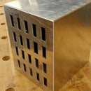
Step 7: Laser-cut Spacers


Everyone has a laser-cutter, right? Well maybe not, hopefully you can access one through your local workshop or friend. You will need this for the mod to make the glasses wearable.
I made a set of spacers, which we use inside the goggles for the NeoPixel rings. They press-fit into the rings and then you can see through the center. That's the magic behind making the LED goggles wearable.
The total thickness for the spaces that is needed is 1/4" — this gives comfortable space between the back of the NeoPixel rings and the front of the LEDs on the rings. I cut out two 1/8" acrylic pieces for each eye, which we will later adhere together. So, each person gets four spacers. Cut some extras for the next class.
The Illustrator file is included in this Instructable. Feel free to use it.
If you don't have a laser-cutter, you can probably source the correct spacers from McMaster.
Attachments

Step 8: Make Instructor's Kit

First, make your "Instructor's Kit" from the Adafruit documentation. We will go over the exact steps for this in the Instructable. Just skip the Write Animation Code and Charge Batteries steps.
When you are done, you should be able to look at their prebuilt test sequences to make sure your kit works.
After you are done, return to the Write Animation Code step.
Step 9: Write Animation Code

I wrote several custom animations for the LED Goggles. The fun part is improving the code from the basic test sample provided by Adafruit.
Mine includes circular patterns of various flavors and more. I hope to improve them. They are on GitHub, here. Feel free to use them, modify them, etc.
One trick: the battery life is low and so if you have the pixels at full brightness with all of them on, the battery will drain quickly. Having 1 or 2 on each eye on at a time will make the batteries last much longer. I keep the brightness at 1/3rd the full value, which is plenty bright.
Step 10: Charge Batteries

The batteries for each of this kits may not be fully charged.
On the day before the workshop and using the little USB charger that came with the kit, fully charge each battery. A green LED will indicate a full charge.
Step 11: Software Configuration


The Trinket Software configuration is a bit of a rigmarole for those who are uninitiated into the dark arts of boot-loaders.
So here's the trick. The morning of the class, email your students and let them know to be prepared. Something like this:
* Please be on time, there's a lot to go through! And we don't want to be rushed at the end.
In preparation:
** bring a laptop! you will need this for programming the LED Goggles and setting up the development environment
** Install the Arduino development environment on your laptop
https://www.arduino.cc/en/Main/Software
Then run the program. This will make sure it launches correctly and also creates a folder called Arduino in your documents directory.
** I made some Arduino LED Goggles sketches for us to play with. You'll want to download them here:
https://github.com/scottkildall/LEDGoggles
Click on Download Zip (right side, middle of the screen) and find the .zip archive in your Downloads folder.
Open up the zip file, and rename the directory from "LEDGoggles-master" to "LEDGoggles". Then, move this entire directory into the Arudino directory, which is inside your Documents directory.
[end of email]
At the workshop itself..
Some folks will arrive early, some will arrive late. Some will have downloaded the Arduino and samples and some will have neglected to do this. That's just the way people are.
Plan for about 30 minutes for software configuration. Expect things to go wrong. Have your extra laptop for the student that forgot theirs.
* Now, for each workshop attendee, have folks install the Trinket board into their Arduino IDE using the Additional Boards Manager. The best way is to have them follow this Adafruit guide, while you are in the room with them.
* If using a Windows computer, you may have to install the Trinket Windows drivers.
* For Tools->Board, choose either Adafruit Trinket 8MHz or Adafruit Trinket 16MHz. It doesn't matter which one.
* Finally, and this trips me up each time, choose Programmer->USBtinyISP
Loading the Blink Sample
To load activate the Trinket boot-loader, i.e to load a program onto the Trinket, press the reset key for about three seconds and then release it. The trinket will pulse its LED with a slight fade up/down, as opposed to a hard blink. You have 10 seconds to upload your sketch and then it goes into playback mode.
Upload the Trinket_Blink example that I created, or just a modified sample of the standard Arduino Blink, but use pin 0 instead of pin 13. You'll want to get each person's laptop "talking" to their Trinket before the soldering portion of the evening.
Step 12: Peel Away the Wires


Now we're at the fun part...the actual building of the LED Goggles themselves.
Have the students peel away two sets of three wires each from the included bit of ribbon cable. They will discard the middle 4 wires and just use the Brown-Red-Orange and the Black-White-Gray set.
The brown-red-orange one will connect the Trinket to the right eye. The black-white-gray set will go from the right eye to the left eye.
Cut about 2" the black-white-gray set. This will go over the bridge of the nose. Strip the ends of the wires for soldering. Plan to have a few sets of wire-strippers available.
Step 13: Solder Trinket to Right Eye


We only have 2 soldering irons and 4 students, so the soldering portion can be a slow-down. The trick is to make sure the class flows smoothly. So, first we have everyone construct the Trinket to the "Right Eye" NeoPixel ring.
Explain the process like this, referring to the handy Adafruit diagram.
The wire comes through the top of the Arduino, where the USB connection is, poking through to the battery side. For the NeoPixel ring, you can solder either from the back or the front. If the wires poke through the front, the construction will be cleaner, but the soldering is more difficult since the LEDs are in the way.
Give students a choice of which direction they should solder the wires in for the eyes.
Solder these wires, which are sort of color-codedfor traditional circuitry.
Brown Wire: GND on Trinket to GND on NeoPixel ring
Red Wire:—> BAT on Trinket to V+ on NeoPixel ring
Orange Wire: —> Pin 0 on Trinket to Input on NeoPixel ring
I try to get the students who seem most adept on the soldering irons first, and those with more perfectionist tendencies to be in the second batch.
After each person is done soldering, have them use small flush-cut pliers to trim the ends of the wires. If you don't have this hand tool in your electronics lab, order some right now. They're absolutely essential.
Step 14: Test the Right Eye

When each student is done with the soldering, have them test one of the NeoPixel sequences using just a single-eye. If there are problems, check their wiring and have them re-solder as necessary.
When it works, give the workshop participant a High Five. They're ready for the second round of soldering.
Step 15: Solder Left Eye to Right Eye and Test

Now, each student will solder the left eye to the right eye.
First, make sure the orientation of the rings line up. The bottom of the left eye should have the same orientation (printing on the circuit board) as the right eye, so that the animations run in sync.
Here's the wiring:
Black Wire: GND of Right Eye to GND of Left Eye
White Wire: V+ of Right Eye to V+ of Left Eye
Gray Wire: Data Out of Right Eye to Data In of Left Eye
The rookie mistake is to solder the gray wire to the Data Out of the Left Eye — in which case the Right Eye will work but the Left Eye will not — so be sly and keep your eye on this part before each of the workshop participants begins their soldering work.
When done, test the Eyes: Run any of the sample sketches and make sure both eyes are working. If they don't work, check the wiring and re-solder as necessary
When the soldering is done, give the workshop participant a High Ten — a High Five for each eye.
Step 16: Begin Construction: Clip Tabs

The electronics are done. Time to get crafty!
Bust out the plastic goggles from the kit. The first thing we will do is snip off the plastic tabs on the goggles. This gap is where the wires between the two eyes will go.
At this point, the second group will be finishing up the soldering, so your attention will be divided between eager crafters and the solderers.
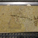
Step 17: Make LED Diffusers


We will cut out tracing paper to help diffuse the direct light from the LEDs.
Unscrew the plastic eyepieces from the eyes. There will be a clear lens and a dark lens. Well, technically not lenses since nothing gets magnified, but you know what I mean.
The dark lens will end up being on the outside of the goggles and the clear lens on the inside. In-between the two pieces, we will put a layer of tracing paper to diffuse the LED glow of the NeoPixel ring. This is why the dark lens will go in front — it helps obscure the tracing paper.
Using the tracing paper, everyone should trace circles with a pencil and then the interior space with the acrylic laser-cut spacers. Use a pair of scissors to cut out this donut shape and fit it onto the eyepieces.
Step 18: Hot Glue the Spacers


Now, hot glue the acrylic spacers directly to the clear lens. The kit I made has two spacers, so this means hot-gluing a spacer to the lens itself and then a second spacer to the top of the previously-glued one.
Optionally, use an Xacto knife to trim away any hot glue.
When you place this assemblage of the the 2 spacers + the clear lens into the eye piece. You'll be able to see through the center and the LED ring will go on the outside.
Step 19: Assemble the Goggles


Put the Right Eye to Left Eye Goggle wires (the black-gray-white strand) through the notch in the goggle frames and screw each eyepiece in. Then, fit the NeoPixel rings over the insert. They should be press-fit, or close to it.
Now, using the hot glue, and this is why we chose the black hot glue, coat over the exterior of the NeoPixel rings so that there is as little light leakage as possible. You may want to hit that interior portion, where the NeoPixel rings meet the acrylic inserts, if the press-fit is not 100% there.
Step 20: Velcro in the Trinket and Battery


Using adhesive velcro, attach velcro pieces to the elastic band behind your head, one for the Trinket and for the battery. Then adhere the velcro to the battery and to the Trinket (battery side). This will keep the Trinket and battery on your goggles instead of dangling loose.
Give yourself some slack, since the elastic band will stretch when you put them on your head.
You can always detach the battery for USB charging, as needed.
Step 21: Done!

Put them on! You are done.
At this point, if you have extra time, as an Instructor, you can work with folks and show them the different sequences. Some people will still be assembling the goggles.
I found that going through the code isn't an effective use of time, but for those who are programming-inclined, there is plenty of Arduino code in my GitHub archive. for anyone to tinker with.
One future modification that I would like to make is to 3D print an actual case for the Trinket and battery, as well as an on/off switch for the device.
I hope this was helpful!
Scott Kildall
For more on electronics and other projects, you can find me here:@kildall or www.kildall.com/blog


![Tim's Mechanical Spider Leg [LU9685-20CU]](https://content.instructables.com/FFB/5R4I/LVKZ6G6R/FFB5R4ILVKZ6G6R.png?auto=webp&crop=1.2%3A1&frame=1&width=306)


