

Introduction: How to Teach an Online Circuits Class With Tinkercad


You probably know Tinkercad for the beginner friendly 3D CAD program, but it also includes a circuit + Arduino simulator that runs in your web browser! I've used Tinkercad for both in-person and online college-level classes and for introductory makerspace workshops. In this Instructable I'll not only show you how to teach your own intro circuits/Arduino class using Tinkercad, but explain the various scenarios where Tinkercad can be useful. The video above gives a detailed walkthrough with a screen recording of Tinkercad, but I've also included screenshots and detailed written instructions in this Instructable!
Note: if you're ready to move beyond the basics and into more advanced Arduino programming, then check out this playlist.
Supplies
Computer with internet access
Step 1: What Is Tinkercad Circuits?
Tinkercad circuits is a fully functional Arduino+Circuit simulator that runs in your web browser. You access it by logging in to Tinkercad and clicking Circuits in the left menu (sometimes people have trouble finding it since Tinkercad defaults to the CAD program first). While circuit simulators have been around for decades and there are free ones that run in a web browser like Circuit Lab, nearly all of them use "schematic view," with symbols that represent circuit components. These schematics will be familiar to people with engineering and physics backgrounds, but they're not great for beginners. Tinkercad provides a "breadboard view" with graphics that look like the physical circuit parts you would use in real life, which is a much more beginner-friendly approach. The ability to simulate an Arduino and run code directly in the web browser is an added bonus.
Step 2: When Should You Use Tinkercad Circuits?
I've found Tinkercad Circuits useful in any of the following scenarios:
- For active learning/flipped classroom format in large lectures. I teach a 150-student class at Cornell, and traditionally we would have two lectures per week where students just watch the instructor build circuits/program the Arduino on a projector, then they'd go to one lab a week to do their own hands on activities. Having 150 students cram laptops + breadboards + Arduinos on tiny lecture hall desks isn't feasible, but I can have them all bring laptops and use Tinkercad (note: check if your school's library or IT departments have loaner laptops for students who don't have them). This is a great way to introduce programming an Arduino and even basics like using a breadboard and a multimeter. Having the students follow along with me in lecture keeps them much more engaged.
- If you have to teach an electronics/Arduino class fully online, due to a situation like the COVID-19 pandemic. While simulations are never a complete replacement for real hardware, they're certainly better than nothing if you don't have any other options. Tinkercad can help you keep an online class engaging, instead of just having students passively watch lectures.
- For remote/online debugging of circuits. Thankfully, we were able to distribute physical Arduino kits for students to use at home during the COVID-19 pandemic. However, we found that TAs and students had a very difficult time debugging circuits over Zoom. It's hard to hold a breadboard up to a webcam and see what's going on. We had students rebuild their circuits in Tinkercad and then screen share in Zoom. This makes it MUCH easier to see all the connections and help debug. So, Tinkercad can be a good supplement even if you have hardware kits available for your class.
- For introductory makerspace/library workshops (getting started with Arduino, circuits for non-engineers etc). Many people attending these workshops probably don't have their own Arduino at home. Tinkercad gives them a way to keep exploring and practicing what they learned without needing to spend any of their own money. Makerspaces/libraries may also choose to offer online classes anyway during non-pandemic times because of the convenience for people with busy work/school/family schedules etc.
For the rest of this Instructable, I'll go over how I would teach a one-hour class for the latter scenario.
Step 3: Starting a Class

- Tell people to create an account at www.tinkercad.com before the beginning of the class. This will save you time at the beginning.
- Share your screen in Zoom or whatever online platform you're using. Tell people that they should open their own browser tab so they can follow along with you. Most people probably don't have two monitors, so you'll need to go slow and pause frequently so they can switch back and forth between Zoom and their own Tinkercad window.
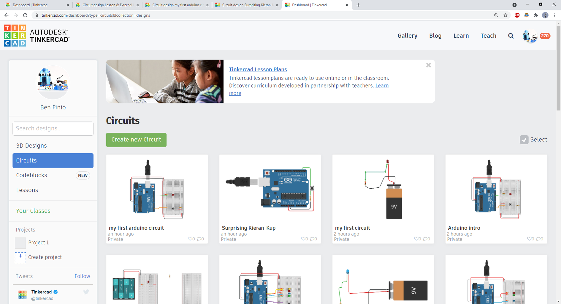
- From the main Tinkercad page, click Circuits on the left, then click Create new Circuit toward the top. Tinkercad likes to give things funky random names - click the name in the upper left and give it something that will make sense when you come back to it in the future, like "My First Circuit."
Step 4: Basic LED Circuit

Get people comfortable with the interface by having them build a basic LED circuit. No Arduino yet!
- Click and drag to bring circuit parts from the right-side menu out into the editing area.
- Click on any component lead to start a wire. Click points to route the wire, and end it on another component lead.
- Click and drag parts to move them around, use the rotate button in the upper left to rotate them.
- Use the scroll wheel to zoom in and out. Click and drag a blank area on the screen to pan.
- If you lose your circuit, click the "Zoom to fit" button in the upper left, just below the rotate button.
- Have everyone build a basic LED circuit with a 9V battery, LED, and 1K resistor as shown. Don't bother explaining Ohm's Law - the LED will light up just fine.
- Make sure the LED's anode is connected to the battery's positive (red) terminal.
- Explain wire color-coding: red for positive, black for negative. The other color doesn't really matter. As you build more complicated circuits, you may want to use other colors for other things (maybe one color for inputs and one color for outputs).
- Press the Start Simulation button in the top right, and the LED should light up.
Pause at this point and make sure everyone is caught up. If anyone has trouble, you can ask them to share their screen so you can help them debug.
Step 5: Optional: What Is a Microcontroller?
For an intro class, people probably aren't quite sure what an Arduino really is, or what the difference is between a microcontroller and a computer. I usually explain it like this: a microcontroller is not the same as a computer. It only does one thing. It doesn't have an operating system, you don't install programs and games or check your email on it. It only runs one program at a time. Your house probably has dozens of microcontrollers in it - inside devices like microwaves, washers/dryers, dishwashers, etc. The microcontroller is the brain that controls what happens when you press the buttons. We just build a simple circuit with an LED that's always on. We'd like to program something that can turn that LED on and off for us automatically. This opens up the door to all sorts of more complicated projects where you could use a microcontroller, like robotics, home automation, and motorized/LED art projects.
Step 6: Add an Arduino
Have everyone start a new circuit and add an Arduino:
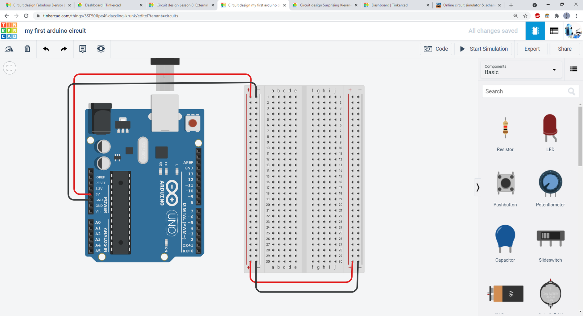
- This is a matter of personal preference, but I prefer NOT to use the prebuilt Arduino+breadboard circuit under "Starters" in the components menu. I like having the breadboard and Arduino in portrait orientation so the writing is upright. I also think it's important to learn how to connect the breadboard power and ground buses yourself, instead of having Tinkercad do it for you. So:
- Drag an Arduino and a breadboard into the editing window. You will need to scroll down in the components list to find them.
- Rotate each one 90 degrees.
- Connect the Arduino 5V pin to the breadboard + bus. Make the wire red.
- Connect the Arduino GND pin to the breadboard - bus. Make the wire black.
- Connect the left and right-side buses as shown in the picture.
- Emphasize the importance of neat, color-coded wiring. Many students will just click directly point-to-point and leave the wires green. This gets messy!
Again, this is a good checkpoint to stop and make sure everyone is caught up.
Step 7: Open the Code Editor

Click the Code button in the top right to open the code editor. I prefer to teach with the text editor, so that's what I'll use going forward, but if you want to focus more on the programming aspect, you can stick with the blocks editor. This is how I usually explain this code to people - don't worry about the details of C and the syntax with the curly brackets etc:
The Arduino has a bunch of pins. We use these pins to interface with things like LEDs, motors, buttons, sensors, etc. What this code is doing is telling the Arduino that we're going to use pin 13 as an output, to control something like a button or sensor (the pinMode command). That only happens once. Then, it's going to loop forever. Remember, it only does this one thing. There's no leaving this loop to go check your email. All it does is turn the LED on (the digitalWrite command). Then it waits for 1000 milliseconds (1 second), turns the LED off, and waits for another second. Then it repeats. That's all it does, forever - turn the LED on for a second, and off for a second.
Press the Start Simulation button and zoom in on the Arduino. You should see the little LED next to the letter "L" blinking. That's a built-in LED on the Arduino that's connected to pin 13. Next we're going to add an external LED.
Step 8: Connect External LED

Now, walk everyone through connecting an external LED. Stop the simulation and click the Code button again to switch back to editing the circuit.
- Drag out an LED
- Rotate it 90 degrees
- Connect it to the breadboard as shown
- Connect the anode (the "crooked" leg) to pin 13. This is a good time to point out how the holes of the breadboard are connected, which Tinkercad will nicely highlight for you. You don't need to run the wire directly to the LED - you can put it anywhere in the same row of the breadboard.
- Connect a resistor from the row with the LED cathode (the straight leg) to the breadboard ground bus. Change the value to 220 ohms (again, I don't usually bother explaining Ohm's Law at this point).
Click Start Simulation again and your external LED should blink! If people are having trouble, pause and have them share their screens for some debugging help.
Step 9: Add More LEDs!
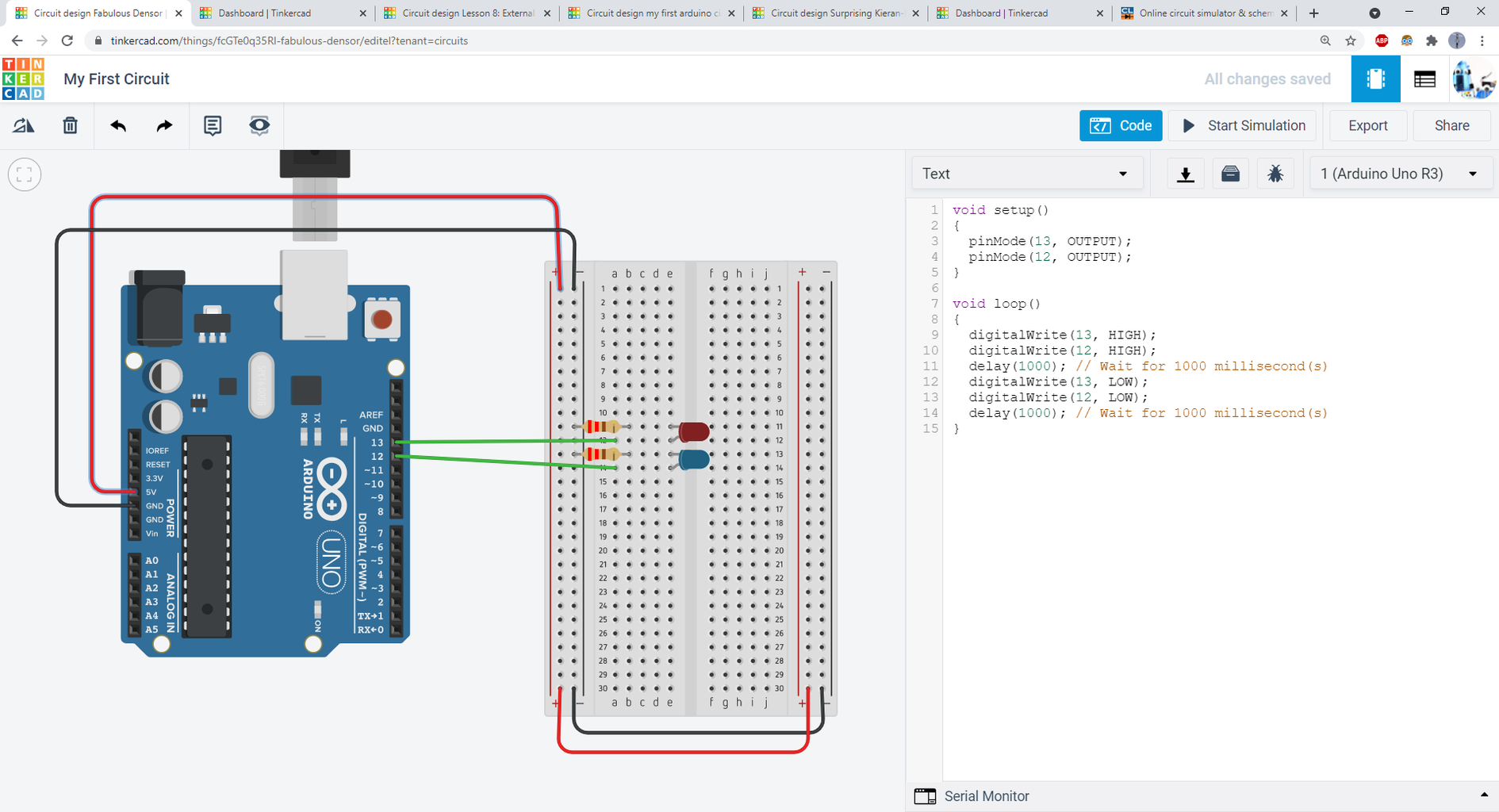
Now for the fun part. Challenge your participants to use what they have learned so far to add another LED. You can keep this very structured (e.g. "add an LED to pin 12 and make it blink at the same time as the first LED") or make it more open ended (e.g. "add another LED to any pin you want and make it blink however you want"). The screenshot above shows the simple former case. But, for example, you could make the LEDs blink out of sync (so one is on while the other is off), make three LEDs for a traffic-light style blinker, etc.
The important think to note here is that participants can do this JUST by copy/pasting existing lines of code, and copying the wiring for the initial LED. They don't need to write any code or wire any new circuits from scratch. I've found that people who are completely new to Arduino and circuits can usually figure this out in a few minutes, but make sure you're supportive/encouraging and help people out if they get stuck. You want to lead them to that "aha, I did it" moment of success!
Step 10: Optional: Buttons

If you have time remaining, you can introduce buttons. The context here is that an LED is an output. Many microcontroller projects also involve inputs - not just buttons, but other sensors that can measure things about the environment like temperature, force, or distance. Inputs are the key to making interactive projects.
The picture above shows a screenshot and example code. Again, there is a built-in demo for this under Starters but I prefer not to use it because the button isn't on a breadboard, and it's important to practice using a breadboard. You will need to walk people through the mechanics of connecting the button properly, as this can be confusing at first. Make sure you zoom in so they can see all the connections clearly.
Once you've added a single button, again you can add an open-ended challenge here, like adding a second button to control a different LED.
Step 11: Conclusion
Many people may have questions about where they can go to learn more, or where they can buy their own parts. For starters you can point them towards Tinkercad's built-in tutorials. Go back to the main Tinkercad page, click Learn at the top, then switch from "3D" to "Circuits" in the drop down menu. You can then click through Starters, Lessons, and Projects (you have to get all the way to Projects for the Arduino stuff - I find the naming convention here a little confusing). For parts, I usually point people to SparkFun and Adafruit, since they have a ton of good tutorials and will offer much better customer support than you'll get if you buy random parts on Amazon.
That's it - I hope you found this helpful! If you have questions or your own story about using Tinkercad to teach online, please leave a comment below.


![Tim's Mechanical Spider Leg [LU9685-20CU]](https://content.instructables.com/FFB/5R4I/LVKZ6G6R/FFB5R4ILVKZ6G6R.png?auto=webp&crop=1.2%3A1&frame=1&width=306)


