

Introduction: How to Troubleshoot a PCB Design?


Every time I design a PCB I want to push my limits a little bit and try something that I never tried before, this time I wanted to add possibility to program this board without external programmer. I found some cheap USB to UART converters called CH340G, the problem is that I have never used it before and it is not well documented on the internet. Eventually I got it working, I needed to add just 3 capacitors. And I thought that instead of making a video about this project, I will make a video about how I troubleshoot it. Some tips and tricks for your PCB problems.
Instructable sponsored by:
JLCPCB 10 boards for $2: https://jlcpcb.com
Step 1: Solder All of the Components

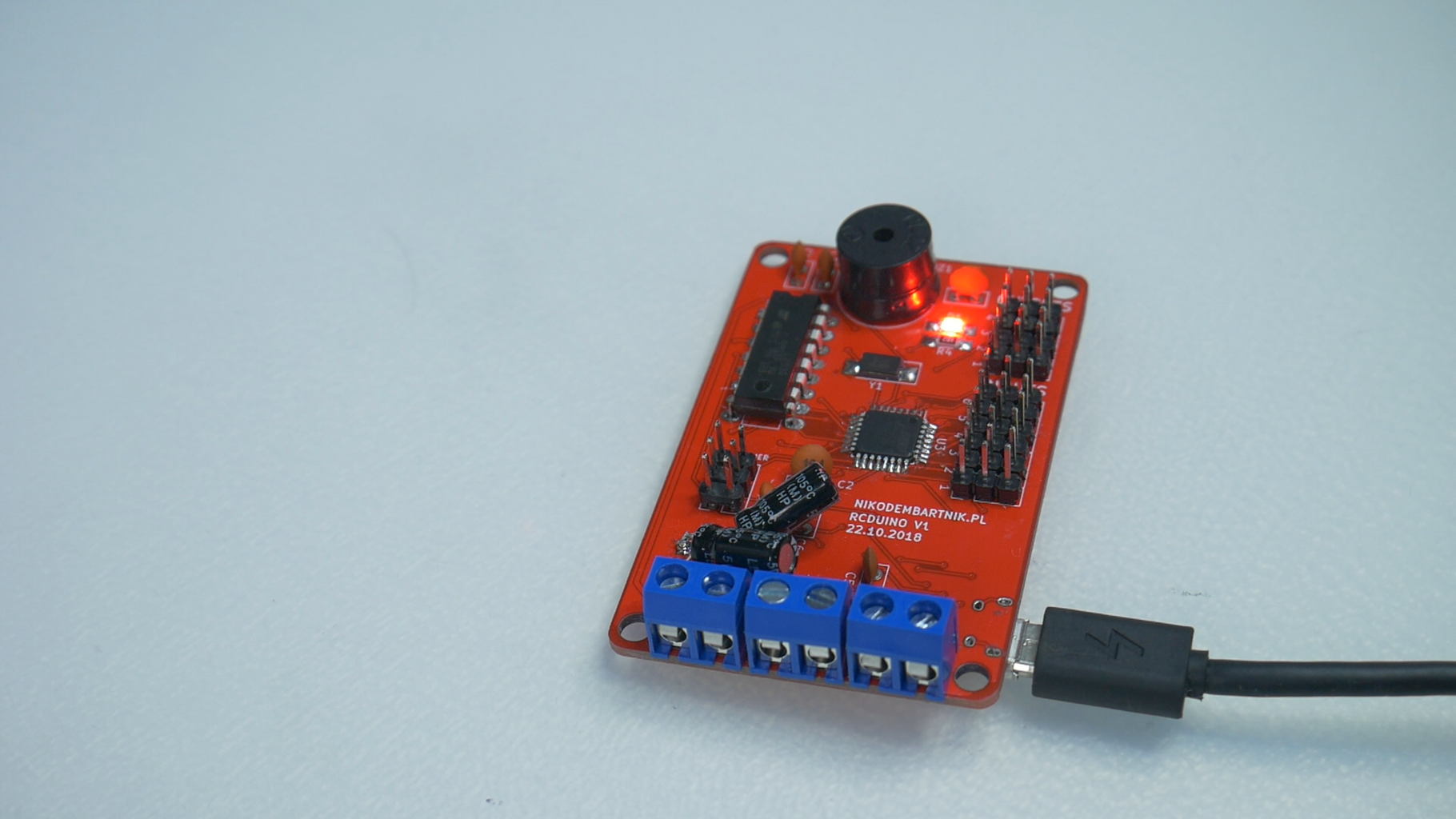
The first step is to solder all of the components, all of them, not just a few to test a PCB, all of the components that should be on the final PCB. Otherwise, you wouldn’t test a PCB completely. It may work fine without some components but once you solder all of them it can stop working completely.
Step 2: Test Your PCB
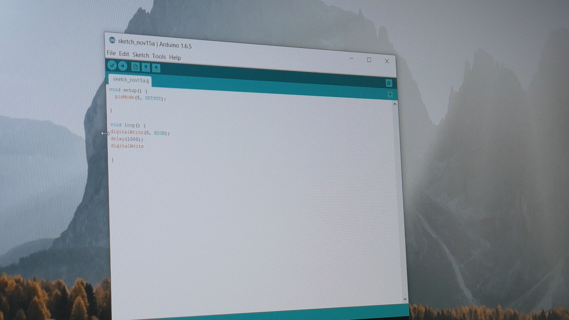
To find if there are any errors, test your PCB. If there is a microcontroller, write a sketch to test all of the functions of your PCB. Check all of them at once or one at a time. If everything works fine don’t worry be happy but if something is wrong, keep reading. If you don't have any microcontroller just test your circuit with a multimeter or power it and test if it works as it should.
Step 3: Check Connections


If you found out that your PCB is not working as it should the first thing to do is to check all of the connections with a multimeter. Check for shorts or open circuits. Set multimeter to ohms measuring or to buzzer mode and check every connection, to make it easier use your schematic and PCB layout.
If you have an access to a microscope even the simple one and need to troubleshoot soldering of SMD components, maybe this is a good solution for you. I am using a microscope sometimes to check if there are any shorts or just to check if I soldered something properly. Overall it’s not very useful in an electronics shop, and this is not something that you must have but when you are working with tiny components it’s nice to have one.
Step 4: Check Your Schematic and PCB Layout

If everything on a PCB seems to work fine, take a look at the schematic and PCB layout, maybe ask a friend to check it with a fresh view. Try to find what may cause a problem. This is an obvious step but sometimes taking a day off and looking at the schematic next day give you this fresh view, it is way easier to find mistakes (like VCC connected to both sides of an LED), Making a clear schematic is a key there, if you have a clear schematic it's better for you and it's better for others.
Step 5: Try to Find Solution Online:
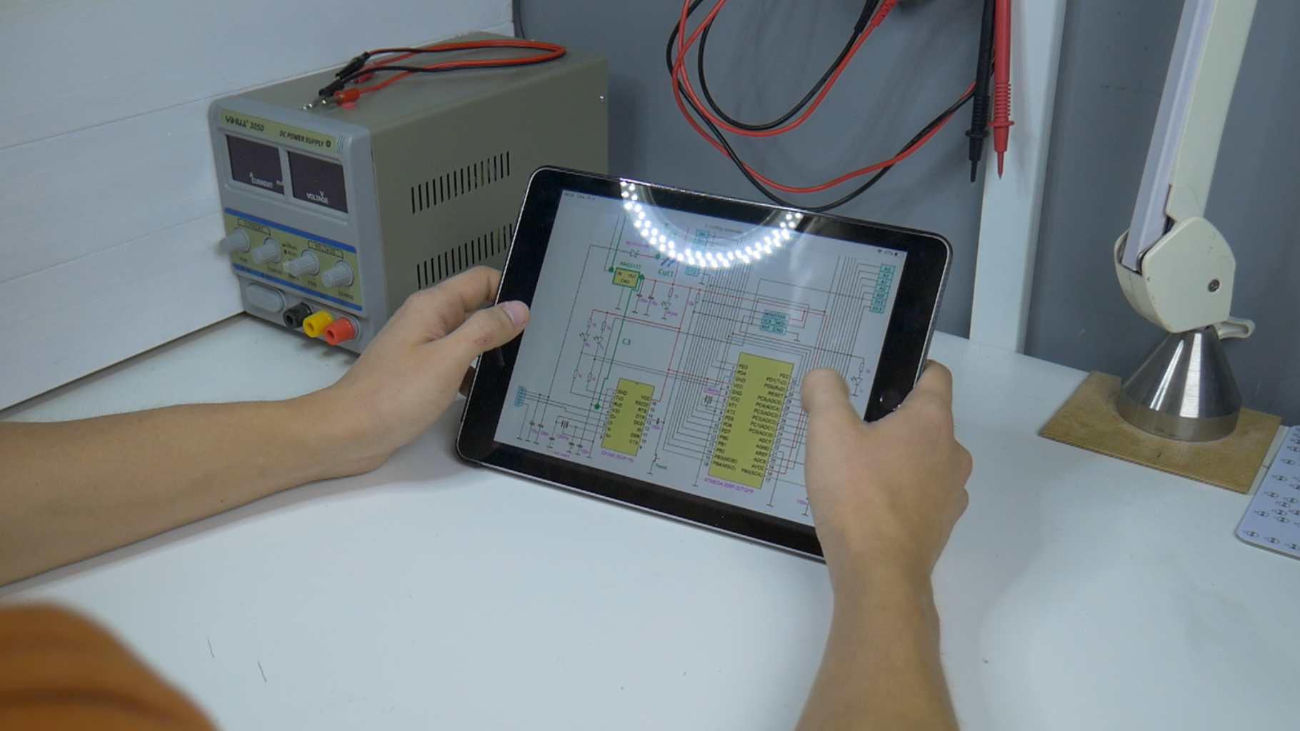
If there are some components that are not working, try to google them and find other peoples schematics that use your part, check how they connect it to the rest of their project and find what is different between those schematics and yours. Of course remember that not everything that you found on the internet is true, but if a part is connected the same way on several schematics we can assume that this is how it should be done.
Step 6: Ask for Help on the Forum:

I don’t really like this one probably because of electronics forum community in Poland, but if you can’t find a solution for your problem, try to ask for help on the forum. There are a lot of electronics enthusiast that will be more than happy to help you, Be nice, post your schematic and describe your problem as detailed as you can. Hopefully within a day or two electronics gurus will help to solve your problem.
Step 7: Fix It!


Once you found all of the problems try to fix them, maybe solder a cable, a capacitor or cut a trace with I knife like I did. To save some money try to fix problems on the PCB that you already have, then change your schematic and reorder your PCB.
And here is a simple tip to avoid mistakes on your PCB it’s called prototyping. Before ordering a PCB or even before drawing a schematic, prototype your idea on a breadboard or protoboard check if everything is working as it should and then create a schematic out of that. That’s the easiest way to avoid any mistakes but sometimes it’s hard to prototype because of very small components that are surface mounted.
I used to prototype all of my projects but because I am using smaller and smaller components, and because I don’t have that much time because of amount of the projects that I am doing I do not prototype almost any of my projects.
Step 8: Conclusion
Don't blame yourself for those mistakes, everyone makes mistakes, mistakes are there to learn out of them, that's a good thing. Just don't repeat your mistakes. Try to be better every time!
I hope that this was helpful for you, if you have any more tips leave them in the comments below!
Happy making!


![Tim's Mechanical Spider Leg [LU9685-20CU]](https://content.instructables.com/FFB/5R4I/LVKZ6G6R/FFB5R4ILVKZ6G6R.png?auto=webp&crop=1.2%3A1&frame=1&width=306)


