

Introduction: I-Cuckoo Clock Using an Arduino & Stepper Motor to Repair & Synchronize a Broken Cuckoo Clock


Using an ESP32 WROOM 32D Microprocessor & Stepper Motor to Repair & NTP Time Synchronize a Worn Out Regula 25 Cuckoo Clock. This modification contains 3D printed parts but the parts could be faily easily made from wood/metal.
This project uses a Regula 25 Cuckoo Clock movement which are very common and worn out ones should be cheap and easy to find.
I purchased an old Cuckoo Clock from Ebay and found three of the time train bushes & pivots were very worn. The pivot holes should be perfectly round and there should be no side to side movement of the gear pivots in the pivot holes.
Rather than re-bush the movement/replace the gears I decided to remove the first worn gear to disable the escapement and drive the clock from an NTP syncronized stepper motor.
Disabling the escapement from the clock means the clock/hands will free run when the chain gear for time is rotated. By controlling the stepper motor attached to this gear allows precise control of time keeping via a NTP server.
I attempted to keep the clock looking as original as possible so the controls are hidden behind the top ornament that is hinged so it can be flipped up for access. I have also added a pendulum drive & with the non functional time weight left in place it still looks like it's clockwork.
The pendulum drive and control wiring are hidden behind a extended back plate and cable channel on the roof.
See this clock on my site here brettoliver.org.uk
Supplies

ESP32 Wroom32D Microprocessor 1 off
ULN2003 5V Stepper Motor + ULN2003 Driver Board 1 off
3144E Hall Effect Sensor Module 1 off
Veroboard 95 x 127mm 1 off
MP1584EN Regulator Module 1 off
Quartz Pendulum Drive Unit Module 1 off
Meccano Spur Gear 57 Tooth Part 27a (from Ebay) 1 off
You will also need wire. I used 0.5mm solid core wire and 3D print material.
If you do not have a 3D printer you can view the included FreeCAD files and fabricate from wood/metal.
Step 1: Features & Functions


NTP precision as time is fetched from an NTP server to synchronise the cuckoo clock time.
Cuckoo clocks are very bad time keepers and tend to not to chime exactly on the hour/half hour anyway. With this Instructable your Cuckoo Clock will tell the time and also chime precisely.
pic2 The time train is driven by a microproccesor controlled stepper motor attached to the clock time train.
pic1 The clock hands now move once every minute.
Chime is weight and chain driven but is synchronized exactly to the hour and half hour.
Summer and Wintertime is easily set from the control panel by a single button push.
The time part of the clock never needs winding but the chime part will need winding.
Step 2: Donor Clock


The clock was purchased from Ebay as spares or repair for £18.00. Working versions go for around £200 so you don't want to do this modification to a working clock.
The modifications can be revearsed if you want to rebush the clock in the future and revert to the original.
Problems with the donor clock
Pic 1 & 2 Although the clock was complete the case was very dirty and there was a badly repaired joint on the right hand leaf on the top of the clock. Original clock on the left and with the yellow tar/dirt removed and wood repaired the restored clock is on the right.
Pic 3 The digits and hands should be white as can be seen by the clean bit of the minute hand where the clock has been adjusted over the years.
The clock has a thick greasy yellow covering of dirt possibly from tobacco smoke over the 70 odd year life of the clock.
I gave the whole clock a good scrub down with soapy water and wire wool.
I pulled the repair on the leaf apart scaped of the old glue and re-glued with super glue.
The case stain was very patchy and worn in places so I touched it up with water based stain.
Pic 4 The best match I found was called English leather and a 50ml sample bottle contained more than enough.
Step 3: Dismantling the Old Cuckoo Clock 1

Before you start to dismantle your clock take some pictures to show where the parts are located and how they interconnect.
I found this video that shows in detail the functions and disassemly.
Step 4: Dismantling the Old Cuckoo Clock 2


Pic 1 Using the video above remove the chain, weights, movement, cuckoo and bellows.
Pic 2
Remove the carved wooden ornaments from the clock.
The top ornament is held on by screw in a bracket.
The front ornamant is nailed down fron the roof and also from the front.
Carefully prise these off.
Remove the hands and dial. The dial is held in place by 3 pins.
Remove the 2 metal brackets for the top ornamant these are pinned in place.
Pic 3
Remove the fixed rear panel. This maybe pinned/glued so use a craft knife to cut away any glue between the panel and frame.
The panel needs to be removed to allow acces to fit the veroboard and wiring.
Clean and repair the case/ornamants as required.
Step 5: Removing Redundant Clock Parts


In order for the stepper motor to drive the clock the escapement has to be disconnected. The escapement prevents the clock gears from free running and regulates them allowing them to turn a step on each pendulum swing.
To disconnect the escapement you need to remove the first gear in the escapement train. This is labled no8 middle gear in the enclosed diagram (pic 2). The removed gear is shown in pic4.
Pic 1 To remove the gear I just losened the movement nuts A a little bit and then losened nuts B enough so the gear could slip out. If you are carefull no other gears will fall out. While the movement was loose I also removed part 17 "verge escapement" (pic5). This is optional and just clears some space.
Once these parts are removed the nuts can be tightened up.
The pendulem leader (pic6) can also be remove as it's no longer used.
Keep all these parts safe so the clock can be returned to it's original state in the future.
Step 6: Adding the Stepper Motor to the Movement


To replace the removed gear I found a Meccano Spur Gear 57 Tooth Part 27a (from Ebay) fitted very well.
The gear ratio is not too important as the gearing can be adjusted in software.
The Meccano Spur Gear gear is fitted to the drive shaft of a 28BYJ-48 stepper motor (pic4).
A 3D printed bracket (pic5) is fixed under the lower right movement nut.
The stepper motor is hot melt glued to the bracket (pic2) and is able to pivot in place around the fixing bracket.
Pic1 shows the movement in place meshed with the clock "chain gear time" in step 5.
Step 7: Assembling the Clock 1


Pic1 The movement with stepper motor added can now be fixed back in the clock case.
Pic2 The Veroboard is fitted under the roof held in place by the 3D printed Veroboard clamp and the 3D printed rear cover.
Pic3 Fit the bellows & cuckoo back in the case attaching the operating wires.
Pic4 Insert the 3D printed clock rear in place. Bolt through the roof in 2 places with M2 nuts & bolts.
Push M2 bolts through the side of the clock and the rear cover. Nuts are not required over these bolts.
Pic5 The 3D printed clock hanger is bolted to the rear cover.
Take the wiring out through the square hole in the rear cover and through the hanging bracket.
Make sure any moving parts of the clock are clear of any wires.
Step 8: Assembling the Clock 2


Pic1 Fix the 2 off 3D printed side brackets to the case cover.
Pic 3 Then fix the Quartz Pendulum Drive Unit Module (Pic2) to the cover with 4 off M2 screws.
The rear cover fits in the case as before locked in place with the catch removed from the old rear.
Pic 4 Screw the Chain clamp in place under the clock.
Note. The slot in the clamp is oversized to prevent damage to the chain so add some soft foam to make sure the chain is secured.
Step 9: Assembling the Clock 3


Pic 1,2 & 3 On the front of the clock add the carved ornaments removed at the start.
I fix with M2 screws instead on panel pins.
Pic 4 Case ornament affixed.
Pic 5 The top ornament is fixed to the 3D printed hinge comprising of 2 off roofmountbracket and 1 off roofMount.
Step 10: Dial and Sensor Unit

The clock uses a sensor in the dial surround to tell when the minute hand is at the 12 o'clock position.
A small Neodymium magnet is glued to the tip if the minute hand to operate a hall effect sensor as it passes.
A 3D printed Sensor ring with cutouts for the leaves surrounds the dial and houses the Hall effect sensor.
It is fixed with wood screws to the case over the dial.
The small Neodymium magnet is glued to the underside of the minute hand on a copper wire.
Step 11: Clock Wiring


The wiring from the stepper motor is plugged into the stepper motor board mounted on the Veroboard.
Pic 2 & 3 The wiring for the control panel and LED display panel mounted on the roof are taken over the ridge of the roof and terminated on a socket on a small Veroboard at the back of the clock.
Cables from the Veroboard are plugged into this socket.
Pic 3 The wiring is covered by 3D printed covers on the ridge and rear of the clock.
Pic 1 Cables terminated on the small Veroboard at the rear of the ridge of the roof.
The micro USB programming cable can also be seen comming out the back of the clock plugged into the ESP32.
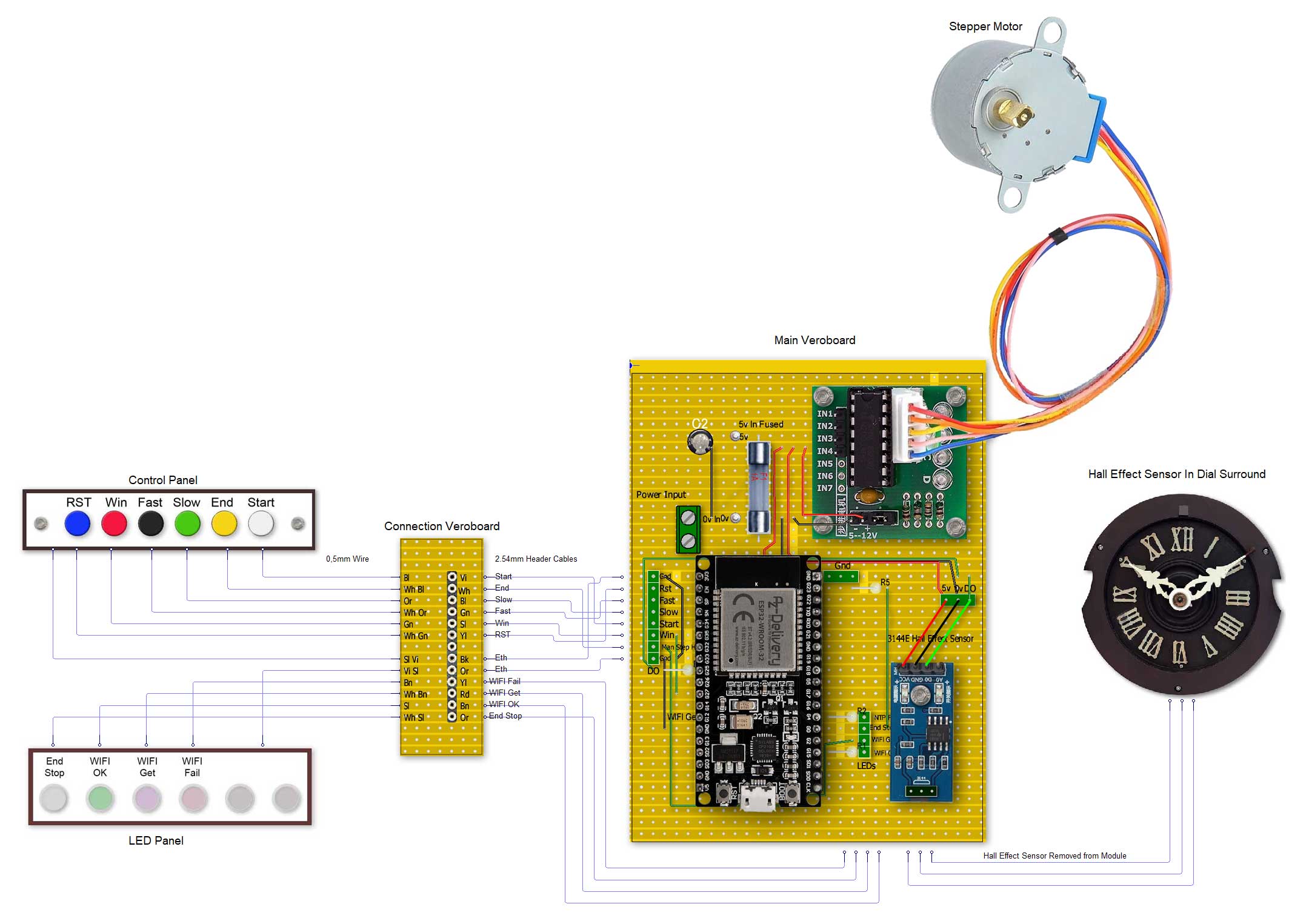
Step 12: Wiring Schematic

The main Veroboard is mounted under the roof.
The connection Veroboard is located at the rear of the ridge cover.
The hall effect sensor is wired through the rear of the case above the dial.
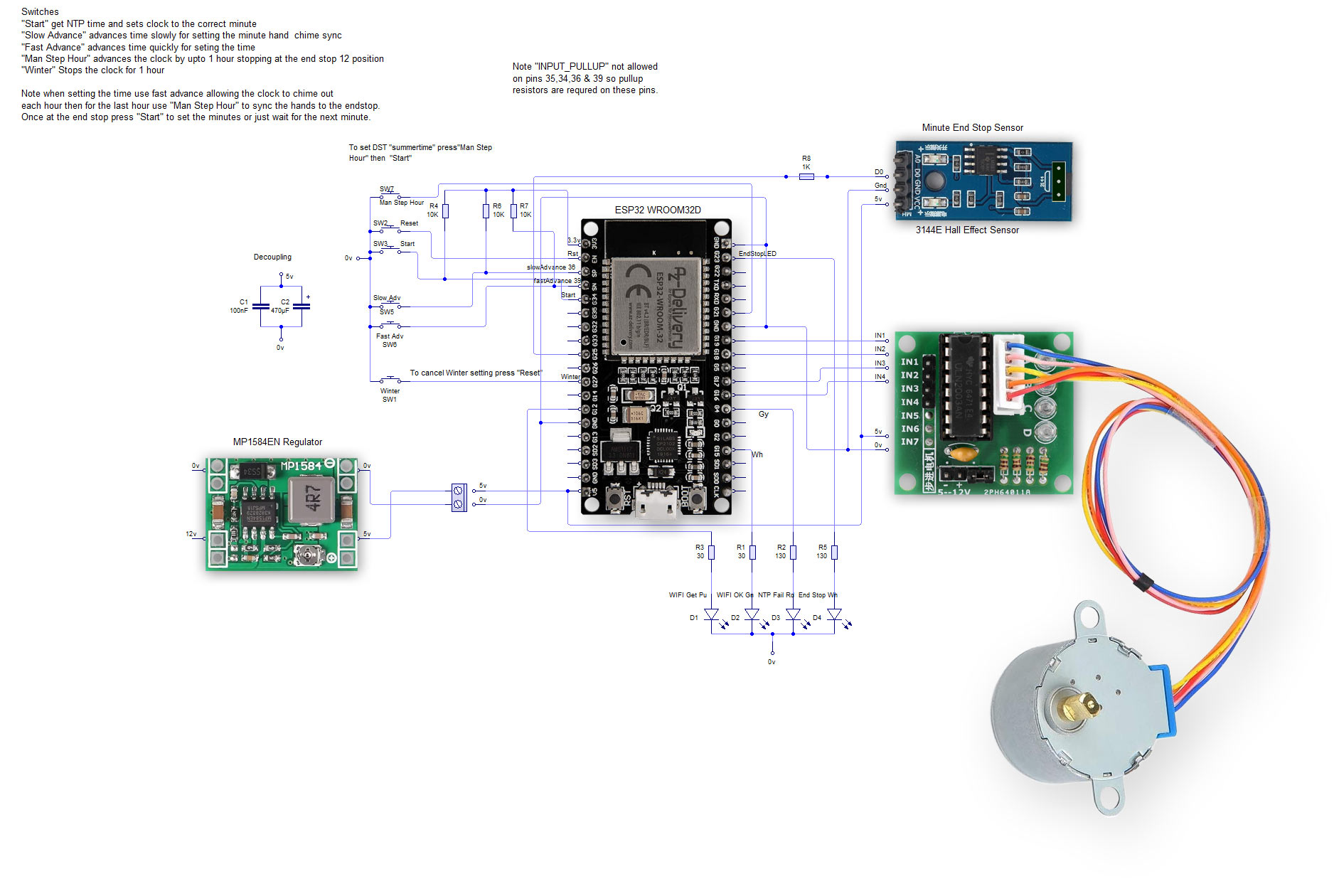
Step 13: Schematic

Step 14: Veroboards


Pic 1 Main board with modules in place.
Pic 2 Main board with modules removed.
Pic 3 Main board rear.
Pic 4 Control Panel Veroboard.
Pic 5 Control Panel Veroboard rear.
Pic 6 LED Veroboard.
Pic 7 LED Veroboard rear.
Step 15: 3D Printed Parts
There are many printed parts to this clock and the files can be downloaded in the "Downloads" section of this instructable.
Step 16: Clock Controls & Indicators


Pic 1 shows the control panel with 6 non locking push switches.
RST- resets the ESP32 microprocessor causing the clock to restart
Win - Sets the clock to wintertime. Note cuckoo clocks can't go backwards so the clock will stop for 1 hour indicated by the "WIFI Get" and "WIFI Fail" LEDs alternating on/off.
Pic 2 Wintertime setting in progress indicator.
Fast - Steps the clock forward quickly
Slow - Steps the clock forward slowly
End - steps the clock on until the minute hand reaches o'clock
Start - steps the clock to the current minute (presumes clock is at End Stop position.
Step 17: Clock Startup Video
This video shows how to start the clock up and initial automatic minute setting.
Step 18: Clock Startup Detail Get NTP Time


On power up the clock will log into your router and then get the time from the NTP server set in the code.
Pic 1 Indicators when logging into the router/NTP time server.
Pic 2 Once time has been fetched the Gn LED lights and the clock will start stepping until the end stop is reached and will then stop.
Pic 3 End stop reached Wh end stop LED lights.
Step 19: Clock Startup Time Setting


To set the hours first lock the cuckoo door to stop the chime as the hour is set.
Pic 1 To lock the door just turn the catch above the door.
To set the hours press and hold the "Fast" button to step the clock forwards quickly.
Pic 2 As the correct hour is reached stop the clock at 12. Use the "Slow" button to stop the minute hand exactly as the "End Stop" LED lights.
Unlock the cuckoo door.
Pressing "Start" will then set the correct minutes on the clock.
Pic 3 When "Start" is pressed the Green LED goes out followed by the "End Stop" LED when the sensor turns off as the hand moves away.
Step 20: Silence the Cuckoo/Chime at Night


To silence the clock at night just lock the cuckoo door by turning the door latch down.
In the morning the clock will chime 12 times when the door is unlocked and will then chime as normal.
Step 21: Download Parts & Code
Included .ino file to code your ESP32 WROOM 32D Microprocessor. You will need to add your router name and password as well as your local NTP time server address.
The 3D parts can be downloaded from here.


