

Introduction: Arduino Class: Input/Output


Arduino Class Table of Contents:
So far you've learned to control LEDs with code, which is one use of Arduino's outputs. This lesson builds on outputs by adding inputs. Your Arduino board can be programmed to listen to electrical signals and take actions based on those inputs. We'll put together a digital input circuit with a switch, and an analog input circuit with a potentiometer (variable resistor).
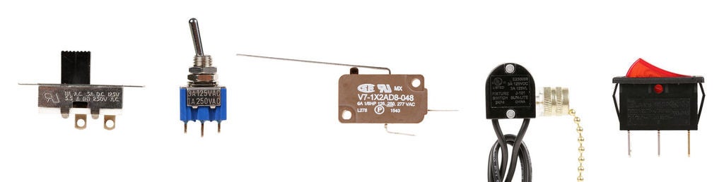
A switch is a mechanical device that connects or breaks a circuit, often using a lever or button. Your tiny tactile pushbutton is just one member of a very large and diverse family. To learn much more, check out the switches lesson in the Instructables Electronics class.
A variable resistor is a component with a changing electrical resistance. In addition to the potentiometer (knob) used in this lesson, you may seek out other variable resistors to try, including but not limited to: pressure sensors (force sensitive resistor aka FSR), light dependent resistors (LDR aka photoresistor), and analog temperature sensors.
Step 1: Supplies
To follow along with this lesson you will need:
- Computer running Arduino software
- Some of the items from the Adafruit Arduino Uno Budget Pack
- Plastic mounting plate for breadboard and Arduino
- Small DC motor
- PN2222 transistor
- 1N4001 diode
Step 2: Digital Input
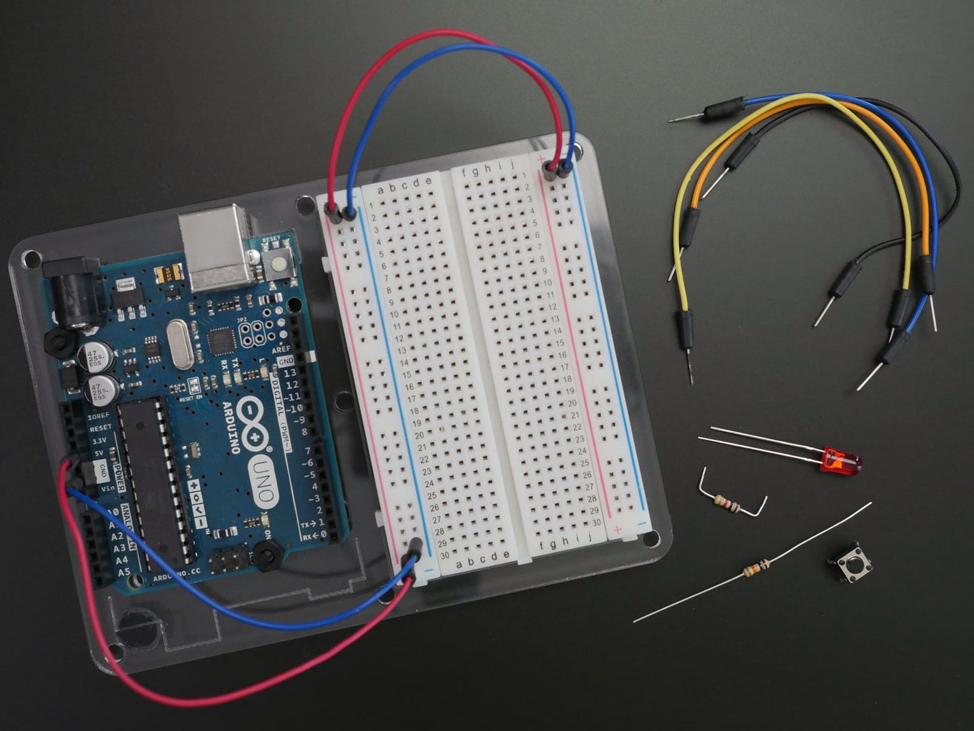
Let's get ready to wire up a new circuit. Grab some breadboard wires, a red LED, 1K resistor (brown-black-red-gold), 10K resistor (brown-black-orange-gold), and a small pushbutton from your kit. Give your 10K resistor the same elbow+trim treatment as your other tidy resistors.
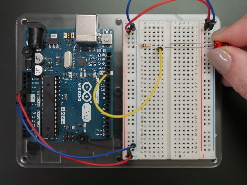
First, connect the LED to Arduino pin 13 like you did in your first circuit, with a wire from pin 13 to the positive lead of your LED, and a 1K resistor connecting the LED's negative lead to ground.
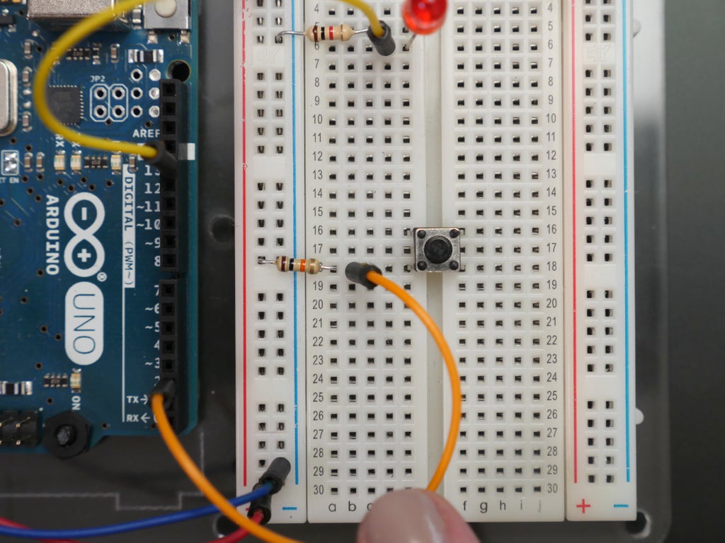
Next, plug in the pushbutton so that it straddles the center dividing line of your breadboard. It should click into place snugly. Connect the 10K resistor from one lead of the switch to the breadboard's 5V power rail. Connect a wire to this same row and plug it into Arduino pin 2.
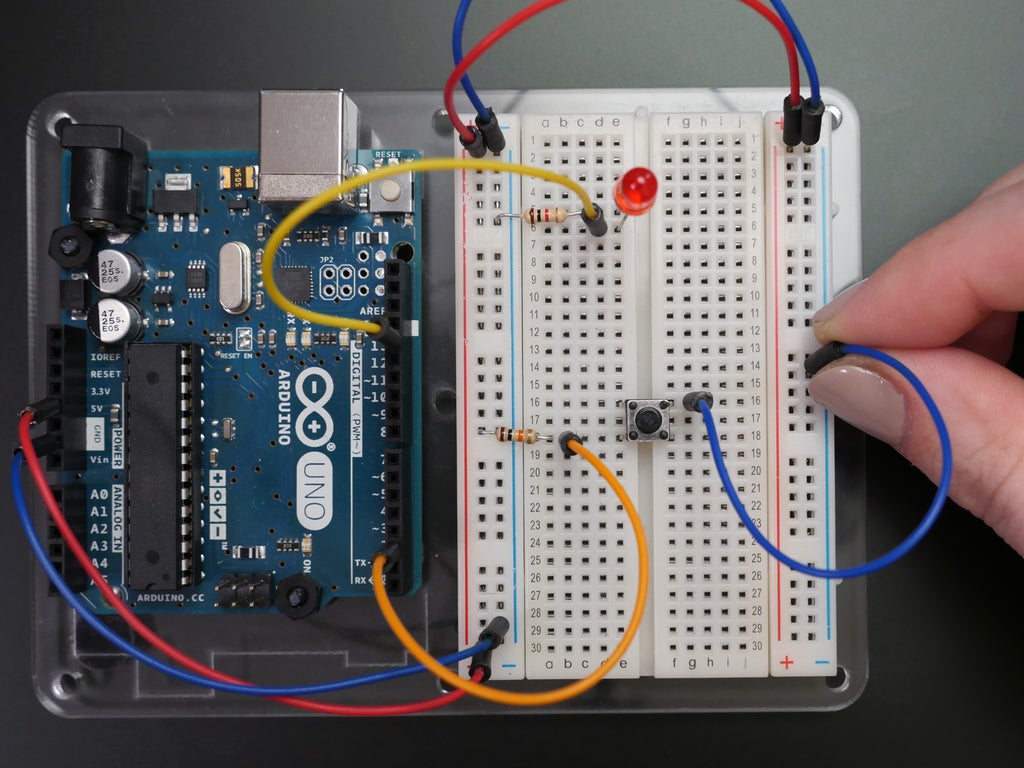
Connect the switch's diagonal lead to ground.
Find this circuit on Tinkercad
Click "Start Simulation" in the Tinkercad Circuits module and try clicking (and holding) the pushbutton to see what the code does. Click the "Code" button to see the sketch.
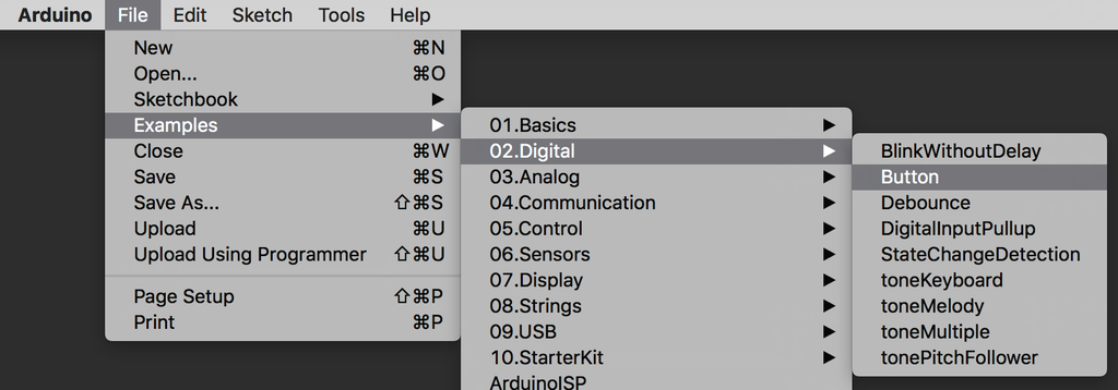
You can find this example in the Arduino software by navigating to File -> Examples -> 02.Digital -> Button. Open it on your computer, and upload it to your Arduino Uno board. The LED should light up, but turn off whenever you press the pushbutton.

Follow along as we explore the code in more detail.
The first lines of this program introduce constants, which are similar to variables in that they store a piece of information. However as you might infer, constants don't change throughout your program, and are therefore great for things like pin numbers. They take up less memory space than variables. Row 39 configures Arduino pin 2 as an input, so we can "listen" to the electrical state of the pushbutton.
In the main loop, a function called digitalRead(); checks the state of pin 2 (which will be either 5V aka HIGH or ground aka LOW), and stores that state in a variable called buttonState. Row 48 contains an if statement that checks to see if buttonState is HIGH (== is a comparison operator, not to be confused with =, which is an assignment operator). If the condition is met, the digitalWrite(ledPin, HIGH); command is executed. If not, the code contained inside the else { is executed instead: digitalWrite(ledPin, LOW);. If statements can exist alone, or with one or more else statements.
Have you noticed that your pushbutton circuit performs the opposite action from that described in the code? I did that on purpose to stretch your mental muscles; let's discuss the switch circuit some more. At rest, the switch leads are not connected to one another. Pin 2 is connected through a beefy 10K resistor to 5V. When the button is pressed, the switch leads are connected, which allows pin 2 to be connected to ground, with no resistor. Since electricity takes the path of least resistance, the pin will sense the connection to ground strongly, and ignore the weak (10K) connection to 5V. But when no other signal is present (when the switch isn't being pressed), that weak connection to 5V is all the pin can sense. So the resistor is "pulling the pin up" to 5V, and so it's called a pull-up resistor. Without one, pin 2 would be not connected to anything until the button is pressed. This is called "floating", and can result in random noise from static electricity and electromagnetic interference. Similarly a resistor can be used to tie a pin to ground, which is called a pull-down resistor.
So to change the function of the button, you can either change the wiring of your circuit, or change the code. The latter is less work in this case, but it's important to remember that might not always be the case when you're building projects on your own. Edit lines 47 (comment) and 48 (if statement) to say LOW instead of HIGH:
void loop() {
  // read the state of the pushbutton value:
  buttonState = digitalRead(buttonPin);  // check if the pushbutton is pressed.

  // if it is, the buttonState is LOW:
  if (buttonState == LOW) {
    // turn LED on:
    digitalWrite(ledPin, HIGH);
  }
  else {
    // turn LED off:
    digitalWrite(ledPin, LOW);
  }
}
Upload the updated sketch to your Arduino Uno board, and check that the button now turns the LED on instead of off.
Arduino pins have built-in pull-up resistors on many of the pins (tiny ones, inside the chip just for this purpose), and you can access one by enabling it in the setup:
pinMode(buttonPin, INPUT_PULLUP);
Change this line of code in your sketch and remove the resistor from your circuit. Upload the code; its behavior should remain the same.
Step 3: The Serial Monitor

Keeping track of everything going on in your program can be an uphill battle. The serial monitor is a way to check in on different spots in your code by reporting back to the computer over the USB cable.
Find this circuit on Tinkercad
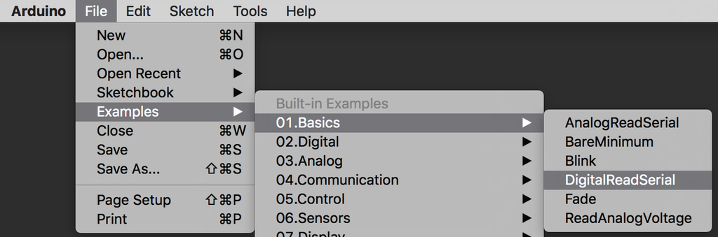
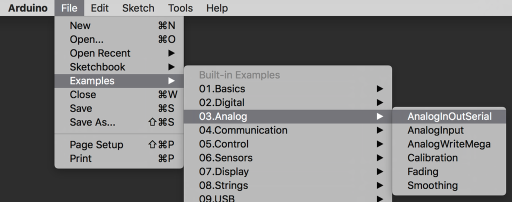
This circuit uses the same button configuration as the previous digital input circuit, but just doesn't use the LED. Load up the code from this module or find it in the Arduino software by navigating to File -> Examples -> 01.Basics -> DigitalReadSerial. Upload this code to your board and click the Serial Monitor button in the upper right of the sketch window. You can also open the virtual serial monitor in the Tinkercad Circuits module above (button at the bottom of the code editor).
To create a serial connection, you should use Serial.begin(); inside your setup. The number 9600 is the baud rate, or data speed, in bits per second (bps). Inside the main program loop, you can use Serial.print(); to send information to the serial port. Serial.println(); does the same thing, but prints on a new line. Line 24 in our code prints the current value of buttonState (HIGH aka 1 or LOW aka 0) to the serial port. So with the serial monitor open, we have a live scrolling view of whatever the Arduino senses at pin 2. The serial monitor is exceptionally handy when troubleshooting, since you can easily compare what you think should be happening to what the Arduino is doing. You can also use serial communication to talk between devices and much more, which you can read about in the Arduino reference.
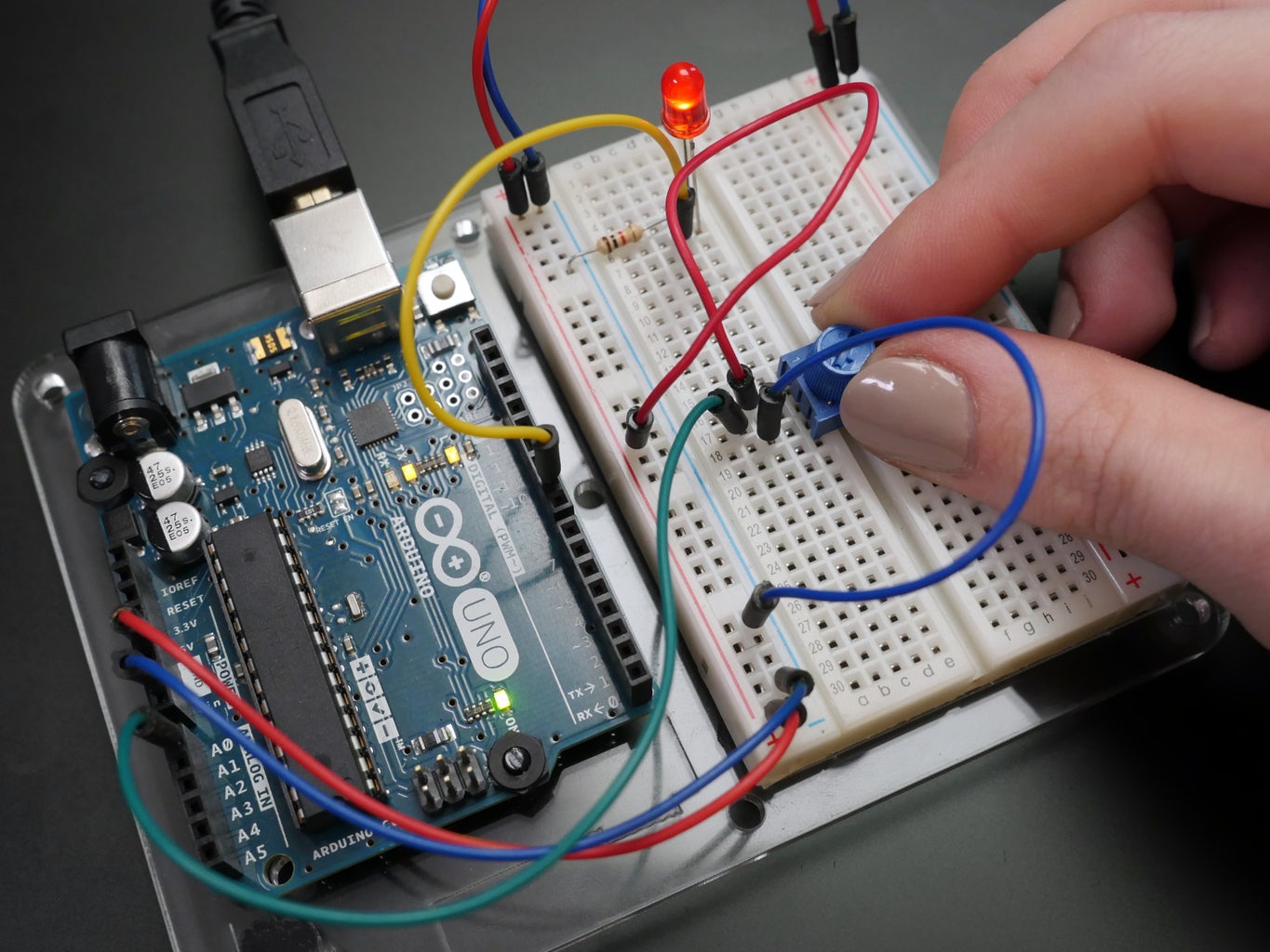
Step 4: Analog Input
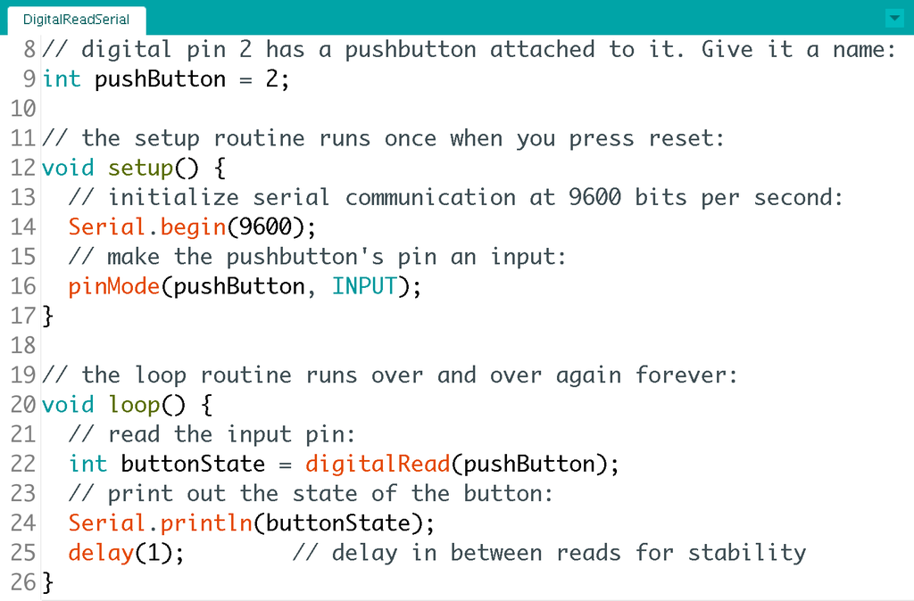
To sense a gradually changing electrical signal, we'll use Arduino's analog inputs, located on the left side of the board. These special pins are connected to the Arduino's analog to digital converter (ADC), equipped to convert an analog signal between 0V and 5V into a range of numbers from 0-1023 (zero counts as a value). Another powers-of-two size, 1024 is 2^10 bytes, aka 1KB. Grab one of the blue potentiometers from your kit and plug it into three rows on your breadboard (with your USB disconnected).
Find this circuit on Tinkercad
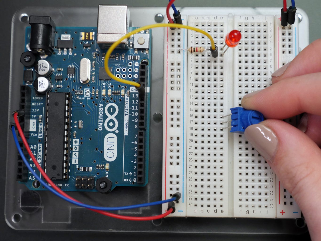
Connect the center pin of the potentiometer to Arduino analog pin A0, and the other two pins to power and ground respectively. Move your LED's control wire from pin 13 to pin 9, so we can use PWM.
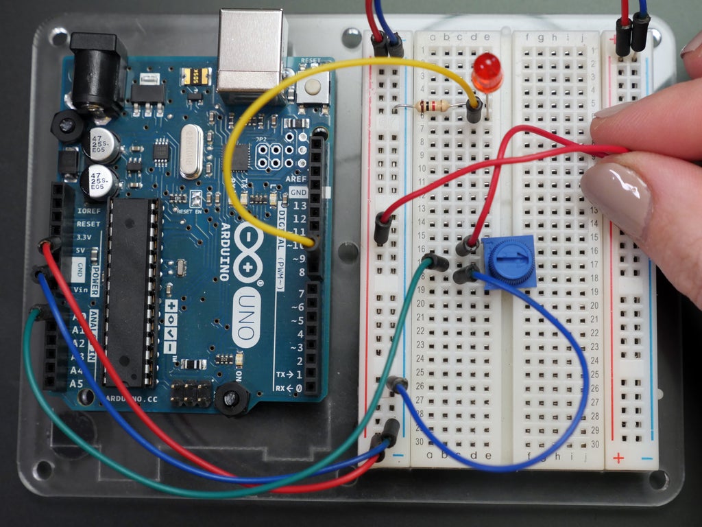
You can get the code from the Tinkercad Circuits module as you have for previous lessons, or find the example by navigating to File -> Examples -> 03.Analog -> AnalogInOutSerial.
Plug in your USB cable and upload the sketch to your Arduino Uno board. Open the serial monitor and observe it and the LED as you twist the potentiometer.

The values read by the analog input are printed in the first column, and the brightness values applied to the LED are printed in the second column.

Let's take a closer look at the main loop of this program:
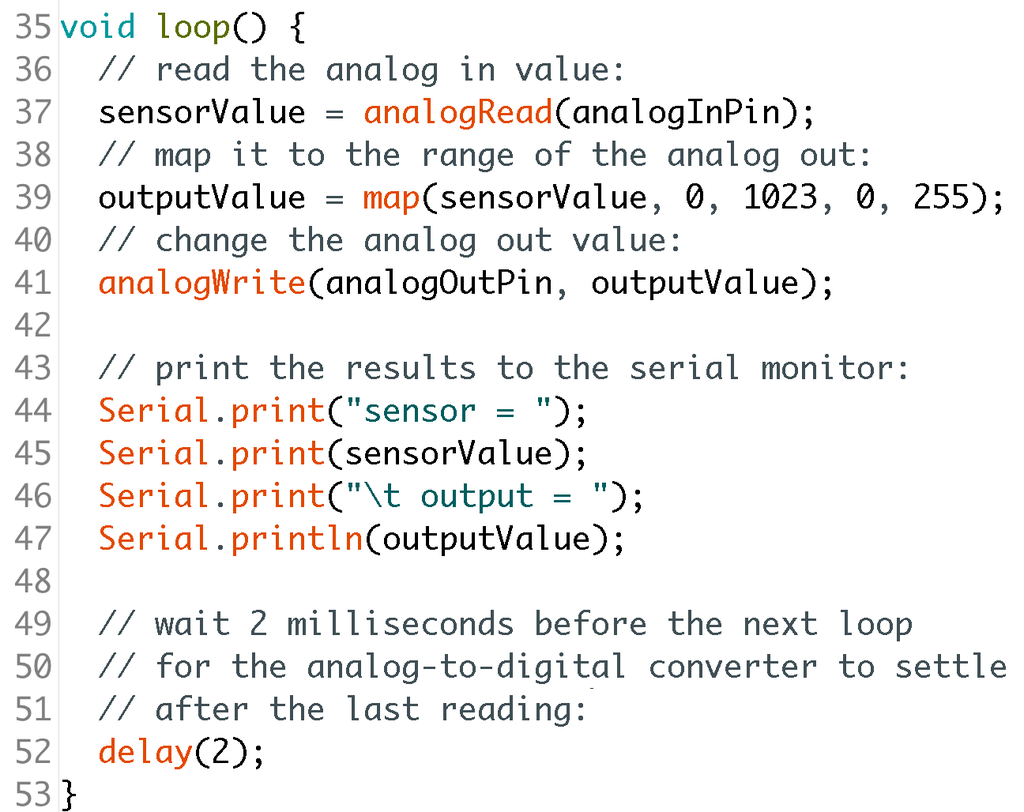
This sketch uses the map(); function on line 39, which takes one range of numbers and massages it into another range. It takes five arguments: the value to be changed, the lower bound of the value's current range, the upper bound of the value's current range, the lower bound of the target range, and the upper bound of the target range. So this line of code sets a variable outputValue to a number between 0 and 255 depending on the position of the potentiometer.
The serial printing commands on lines 44-47 print text labels (inside quotes) and the values incoming from the sensor and outgoing to the LED. Seeing these numbers change together in the serial monitor can really help you understand how functions like map(); work. Keep this in mind when composing and troubleshooting your own sketches!
Step 5: A Moment for Motors
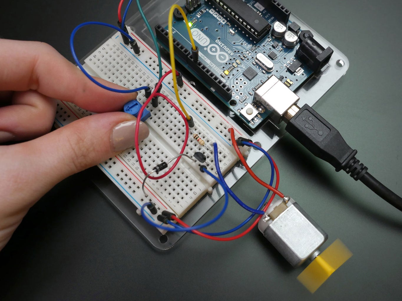
The exact same code used to brighten and dim the LED in the previous circuit can also be used to control the speed of a simple DC motor. This basic motor needs a few extra components to help control it: a small resistor (use your 1K or try a 100 ohm marked brown-black-brown-gold), a NPN transistor (we're using a PN2222), and a diode (1N4001). The resistor is used to protect the Arduino pin from excessive current draw. The diode prevents the transistor from dumping any blowback voltage anywhere it shouldn't (something motors are prone to doing). The transistor acts like an electronic valve, allowing current to flow between its collector and emitter (PN2222 outer pins) in proportion to the signal it receives at the base (PN2222 center pin). Transistors are handy for controlling a rather power hungry component with a microcontroller pin, which can't deliver enough current directly.
Find this circuit on Tinkercad
Unplug your USB cable and build the circuit according to the diagram, minding the flat side of your transistor (faces away from the Arduino in this circuit), as well as the stripe on your diode (on the side furthest from the transistor). If you're using a different NPN transistor (like the 2N2222), your transistor pin connections may be different than those pictured, so look up the datasheet to be sure you're making the following connections:
- Arduino pin 9 to transistor base through resistor
- 5V to transistor collector through diode
- Ground to transistor emitter
- Motor wires to transistor collector and 5V (either orientation)
Power up your board and see what effect turning the knob has on the speed of the motor (use a piece of tape to make it easier to see the motor shaft spinning).

The motor recommended for this circuit draws less than 250mA, but a larger one could require more power than your computer's USB port can deliver. To power bigger motors, lots of LEDs, and other circuits that use more power, you'll need to use an external power supply, such as an AC adapter or battery pack. Additionally, for any larger of a motor, you'd also need a larger transistor. We'll learn how to calculate your circuit's power needs in the next lesson, but by popular request, here's the same motor circuit powered by an external 6V battery pack (separate power rails, common ground):
Find this circuit on Tinkercad
To learn more about transistors and use them in a project, check out the transistors lesson in the Instructables Electronics Class. To learn more about motors and use them to build several fun robots, check out the Instructables Robots Class.
You now know the basic building blocks of most Arduino programs, and have built a few circuits demonstrating their utility. Great work!
Arduino Class Table of Contents:


