

Introduction: LOW COST DIY 500€ CNC MILL


Hi,
in this Instructable I want to show you, how you can build your own CNC-Mill for less then 500€. I designed this machine for CNC-beginners, who don't want to spend a lot of money for their first experiences with CNC machines but also expecting a rigid and professional looking CNC.
This machine is perfect for maker, tinkerer and everyone who wants to start CNC-Machining.
In the pricerange of sub 500€ you will not find any other CNC with these features:
- 710 Watt spindle motor
- MGN linear-rails on all axis
- 1204 ballscrews on all axis
- effective workarea of 250x220mm
- max. travelspeed of 3000mm/min (at 12V)
- high accuracy of 0.1mm in all axis
- super rigidportal frame (out of one piece of wood and aluminium extrusions)
Below on this site, you will find a detailed instruction + a bill of materials (BOM) with links, where you can source the required parts.
The complete CNC is build out of CNC milled screen printing wood plates. So assembling will not be a problem. For the build you don't need any expensive tools like (3D-Printers, CNC or Lasers). The only special tool is a M5 and M6 thread cutter.
Video of CNC in action:
If you like my Instructable, please vote for me in the Build a Tool Contest
You can see the CNC live at Makerfaire Ruhr 2020
I really like to see, when someone has rebuilded the CNC, so please post a photo of the CNC in the comments with "I made it" :-)
Change Log:
- [06.03.2019] Added step "Configure Estlcam for This Machine" + video of test run
- [07.03.2019] Added video of CNC in action
- [15.03.2019] Added photo of Linear Parts
Step 1: Mechanical Parts

The complete CNC is designed in Fusion 360, below you will see the complete CNC in an interactive 3D-model:
Required Parts:
CNC-Milled-Parts:
Here are all required CNC-milled parts. You can buy all the CNC-milled parts in my Online Shop. The total cost of all the CNC-milled parts will be 150€ + shipping.
| Quantity | Description | How the part looks like |
|---|---|---|
| 1x | Y_Axis_Front |  |
| 1x | Y_Axis_Rear |  |
| 1x | Y_Axis_Nut |  |
| 2x | Portal_Side |  |
| 1x | Portal |  |
| 1x | X_Motor |  |
| 1x | X_Bearing |  |
| 1x | X_Carriage |  |
| 1x | Z_Motor |  |
| 1x | Z_Plate_Front |  |
| 2x (normal+mirror) | Z_Plate_Side |  |
| 1x | Spindle_Mount |  |
| 1x | Main_Plate |  |
Aluminium Extrusion Parts:
I am trying to use as much standart aluminium extrusion parts, so it will be relativly easy to source the parts.
| Quantity | Description | Link | Price |
|---|---|---|---|
| 10x | 2040 extrusion angle bracket | Aliexpress | 9,10€ (for 20 pieces) |
| 2x | 428mm 20x20mm aluminium extrusion 6mm slot | dold-mechatronik | 2,07€ |
| 2x | 400mm 20x40mm aluminium extrusion 6mm slot | dold-mechatronik | 3,70€ |
| 2x | 250mm 20x20mm aluminium extrusion 6mm slot | dold-mechatronik | 2,60€ |
| 1x | 330mm 20x60mm aluminium extrusion 5mm slot | dold-mechatronik | 4,26€ |
Nuts, Screws and Washers:
I am trying to be as accurate as possible while counting all the screws and nuts. If you find any fault on the list, please tell me, so I can update the parts list. Also I recommend to buy some more screws.
| Quantity | Description | Where to buy | Price |
|---|---|---|---|
| 84x | M3 T-slot Nut Slot 6mm | 5,60€ | |
| 40x | M4 T-slot Nut Slot 6mm | 5,60€ | |
| 4x | M4 T-slot Nut Slot 5mm | 0,88€ | |
| 32x | M4x20mm DIN912 cylinderhead screw | local hardware store | - |
| 32x | M4x16mm DIN912 cylinderhead screw | local hardware store | - |
| 8x | M4x12mm DIN912 cylinderhead screw | local hardware store | - |
| 8x | M3x16mm DIN912 cylinderhead screw | local hardware store | - |
| 52x | M3x12mm DIN912 cylinderhead screw | local hardware store | - |
| 8x | M3x10mm DIN912 cylindergead screw | local hardware store | - |
| 84x | M3x8mm DIN912 cylinderhead screw | local hardware store | - |
| 6x | M5x20mm DIN912 cylinderhead screw | local hardware store | - |
| 12x | M5x10mm DIN912 cylinderhead screw | local hardware store | - |
| 16x | M6x20mm DIN912 cylinderhead screw | local hardware store | - |
| 8x | M3 nylon nut | local hardware store | - |
| 24x | M4 nylon nut | local hardware store | - |
| 8x | M3 washer | local hardware store | - |
| 6x | M5 washer | local hardware store | - |
| 80x | M4 washer | local hardware store | - |
| 16x | M6 washer | local hardware store | - |
Linear parts and custom machined ballscrews:

For the CNC mill you will need three custom machined 1204 ballscrews. I have attached a drawing with the dimesions at the bottom of this step. Additionally you will need MGN12 linear rails, ballscrew, bearings and housings. Because it was a littlebit hard to source all the parts, I contacted a manufacture, who can supply all these parts for a resonable price. This manufacture will also make the custom machined ballscrews. You can buy all the parts here: Aliexpress
| Quantity | Description |
|---|---|
| 1x | 1204 Ballscrew 425mm |
| 1x | 1204 Ballscrew 395mm |
| 1x | 1204 Ballscrew 200mm |
| 4x | 400mm MGN12 Linear Rail |
| 2x | 250mm MGN12 Linear Rail |
| 12x | MGN12H Linear Rail Wagon |
| 2x | FF10 Ballscrew Bearing |
| 3x | 24mm 1204 Ballscrew Housing |
| 3x | 5 to 8mm shaft coupler (rigid ; not the red or flexible) |
Attachments

Step 2: Electrical Parts

Electrical Parts for the CNC:
Here you will find all the required electronic parts for the CNC mill. For the router you can use the Katsu from Amazon or a Makita RT0700C. Both will fit to the CNC-milled parts.
| Quantity | Description | Link | Price |
|---|---|---|---|
| 1x | 710W 230V spindle motor | Amazon | 59,99€ |
| 3x | inductive limit switches NPN | Aliexpress | 4,44€ |
| 3x | Nema 17 Motors | Aliexpress | 33,00 € |
| 1x | Arduino Uno + CNC-Shield + DRV8825 | Aliexpress | 9,76€ |
| 1x | 12V Powersupply 5A | Aliexpress | 7,05€ |
| some | wires | - | - |
Step 3: The Main Frame


What you need for this step:
| Quantity | Description |
|---|---|
| 32x | M3x8mm DIN912 cylinderhead screw |
| 32x | M3-T-Slot-Nut 6mm-Slot |
| 2x | 400mm MGN12 Linear-Rail |
| 4x | MGN12H-Linear-Rail-Wagon |
| 1x | Y_Axis_Front |
| 1x | Y_Axis_Rear |
| 8x | M6x20mm DIN912 cylinderhead screw |
| 8x | M6 washer |
| 2x | 20x40mm aluminium extrusion 6mm slot |
What you have to do:
At frist you have to cut eight M6 threads inside the aluminium extrusions. After that you need to attach the MGN12 linear rails to the alumnium extrusions by using the M3x8mm screws. Then you have to take the two wood parts and attach them to the aluminium extrusion with eight M6x20mm screws.
Step 4: Y-Ball-Screw


What you need for this step:
| Quantity | Description |
|---|---|
| 8x | M3x16mm DIN912 cylinderhead screw |
| 4x | M3-nylon nut |
| 8x | M3-washer |
| 1x | FK10 Bearing |
| 1x | 1204-ballscrew housing |
| 1x | 395mm 1204-ballscrew with custom end-machining |
| 1x | Nema 17 Stepper Motor |
| 1x | 5x8mm shaft-coupler |
What you have to do:
Now it is time to install the Y-ballscrew to the main frame. At first install the Nema 17-motor to the rear plate and fix it with four M3x16mm screws. Then you can slide the 395mm ballscrew in. Once the ballscrew is in place, attach the FK10 bearing at the front plate. The FK10 bearing is fixed by four M3x16mm screws and M3-nylon nuts.
Step 5: Y-Ballscrew Plate


What you need for this step:
| Quantity | Description |
|---|---|
| 4x | M5x10mm DIN912 cylinderhead screw |
| 1x | Y_Axis_Nut |
What you have to do:
For that step, you have to install the Y_Axis_Nut plate to the ballscrew housing. You do that with four M5x10mm screws.
Step 6: The Portal Side


What you need for this step:
| Quantity | Description |
|---|---|
| 4x | M4x16mm DIN912 cylinderhead screw |
| 4x | M4-T-slot nut 5mm Slot |
| 1x | 330mm 60x20mm aluminium extrusion 5mm slot |
| 6x | M5x20mm DIN912 cylinderhead screw |
| 6x | M5 washer |
| 16x | M3x12mm DIN912 cylinderhead screw |
| 16x | M3 washer |
| 2x | Portal_Side |
What you have to do:
At first you have to connect the two Portal_Side plates to the linear wagons. After that you have to attach the 60x20mm extrusion to the Portal_Side plates by using the six M5 screws. Finally connect the ballscrew housing from the previous step to the extrusion.
Step 7: The Main Plate


What you need for this step:
| Quantity | Description |
|---|---|
| 1x | Main_Plate |
| 16x | M6 hammer nut |
What you have to do:
You have to hammer the 16 hammer nuts to the predrilled holes.
Step 8: Attach the Main Plate to the Main Frame.


What you need for this step:
| Quantity | Description |
|---|---|
| 8x | M4x12mm DIN912 cylinderhead screw |
| 8x | M4 T-Slot mut 6mm slot |
| 8x | M4 washer |
What you have to do:
You have to connect the preassembled Main_Plate to the main frame. The connection is made with eight M4x12mm screws.
Step 9: Portal


What you need for this step:
| Quantity | Description |
|---|---|
| 32x | M3x8mm DIN912 cylinderhead screw |
| 32x | M3-T-slot nut 6mm slot |
| 8x | M4x12mm DIN912 cylinderhead screw |
| 8x | M4x20mm DIN912 cylinderhead screw |
| 32x | M4 washer |
| 2x | 400mm MGN12 Linear Rail |
| 4x | MGN12H Linear Wagon |
| 2x | 428mm 20x20mm 6mm slot aluminium extrusions |
| 4x | 4020 angle bracket |
| 1x | portal plate |
What you have to do:
At first you have to connect the linear rail to the aluminium extrusion.Then place the extrusions on the portal plate. Now screw the extrusions to the extrusions. Don't forget to place the angle brackets.
Step 10: X-Ballscrew


What you need for this step:
| Quantity | Description |
|---|---|
| 4x | M3x10mm DIN912 cylinderhead screw |
| 4x | M3x16mm DIN912 cylinderhead screw |
| 8x | M3 washer |
| 4x | M3 nylon nut |
| 1x | 425mm 1204 Ballscrew |
| 1x | 1204 24mm Ballscrew housing |
| 1x | 5x8mm coupler |
| 4x | M6x20mm DIN912 cylinderhead screw |
| 4x | M6 washer |
| 1x | Nema 17 Motor |
| 1x | X_Bearing |
| 1x | X_Motor |
| 1x | FF10 Bearing |
What you have to do:
You have to place the ballscrew between the two linear rails. The connection of the motor and the FF10 bearing is made by four M6 screws. Don't forget to cut the four M6 threads to the aluminium extrusions.
Step 11: X-Carriage


What you need for this step:
| Quantity | Description |
|---|---|
| 4x | MGN12H Linear Rail Wagon |
| 32x | M3x12mm DIN912 cylinderhead screw |
| 32x | M3 washer |
| 1x | X-Carriage plate |
What you have to do:
Connect the X-Carriage plate to the linear wagons by using the M3x12mm screws and the predrilled holes.
Step 12: Z-Axis Part 1:


What you need for this step:
| Quantity | Description |
|---|---|
| 1x | Z-Plate_Front |
| 2x | 250mm MGN12 Linear Rail |
| 2x | 250mm 20x20 aluminium extrusions |
| 8x | M4x16 DIN912 cylinderhead screw |
| 16x | M4 washer |
| 8x | M4 t slot nut |
| 20x | M3x8mm DIN912 cylinderhead screw |
| 20x | M3 t slot nut |
What you have to do:
Connect the linear rails to the extrusions by using the M3x8mm screws. After that attach the extrusions to the Z_Plate_Front .
Step 13: Z-Axis Part 2:


What you need for this step:
| Quantity | Description |
|---|---|
| 1x | Spindle_Mount plate |
| 1x | Z_Motor plate |
| 4x | M6x20mm DIN912 screws |
| 4x | M6 washer |
What you have to do:
Connect the Spindle_Mount at the bottom of the Z-Axis and the and the Z_Motor plate at the top of the Z-axis. Don't forget to cut a M6 thread inside the extrusions.
Step 14: Z-Axis Part 3:


What you need for this step:
| Quantity | Description |
|---|---|
| 2x | Z_Plate_Side |
| 8x | M4x16mm DIN912 cylinderhead screw |
| 16x | M4 washer |
| 8x | M4 T-slot-nut |
What you have to do:
Place the Z_Plate_Side plates at the side of the Z-axis. Then connect them with the M4x16mm screws
Step 15: Z-Axis Part 4:


What you need for this step:
| Quantity | Description |
|---|---|
| 1x | Nema17 Motor |
| 4x | M3x10mm DIN912 cylinderhead screw |
| 1x | 200mm 1204 Ballscrew |
| 1x | 1204 Ballscrew Housing |
| 1x | 5x8mm shaft coupler |
What you have to do:
Attach the Nema 17 motor to the predrilled holes and connect it with four M3x10mm screws. After that connect the ballscrew to the Nema 17 motor with the 5x8mm shaft coupler.
Step 16: Connect the Z-Axis and the Portal


What you need for this step:
| Quantity | Description |
|---|---|
| 4x | M5x16mm DIN912 cylinderhead screw |
| 4x | M5 washer |
What you have to do:
Slide the Z-Axis into the linear wagons on the X-Carriage. Then connect the Z-ballscrew to the X-Carriage with four M5x16mm screws.
Step 17: Connect the Portal to the Main Frame


What you need for this step:
| Quantity | Description |
|---|---|
| 6x | 2040 angle bracket |
| 32x | M4x20mm DIN912 screws |
| 64x | M4 washer |
| 32x | M4 nylon nut |
What you have to do:
Finally connect the portal to the main frame. You do this by using six additional angle brackets. All the requiered holes are predrilled. Please take a look at the pictures, where the angle brackets are located.
Step 18: Prepare the Spindle


For the connection between the spindle and the machine, I am using the allready existing spindle mount. You simply need to remove the plastic part at the bottom of the mount.
Step 19: Attach the Spindle Mount to the Machine


What you need for this step:
| Quantity | Description |
|---|---|
| 4x | M4x16mm DIN912 cylinder head screw |
| 4x | M4 washer |
| 1x | Spindle mount |
What you have to do:
Place the spindle mount on the Z-axis. Then connect it to the Z-axis with four M4x16mm screws. Once completed, you can slide the spindle inside the spindle mount.
Step 20: Electronics

For the electronics I am using an Arduino Uno with a CNC-shield. This is the cheapest methode to controll the CNC.
For the connection you have to connect the X-Motor to the X-Motor-Port, the Y-Motor to the Y-Motor-Port and the Z-Motor to the Z-Motor Port. Then you have to connect 12V to the board at the blue terminal pins. After that connect it to your PC and flash the software (GRBL or ESTLCAM) to the Arduino.
Now you should be able to move your machine.
(coming soon):
On the machine there are also holders for inductive 12mm end switches in the CNC milled frame. I am still waiting for delivery, so when they arrieved, I will update the instruction.
Step 21: Software
To controll the machine you need 3 types of software:
1. CAD software:
Inside the CAD software you create your 3D-File, which you want to manufature. I personally use Fusion360 for this kind of application.
2.CAM software:
In the CAM software you define the tool path of your CNC machine, here you can also use Fusion360, because it has a build in CAM-module.

3. G-code Sender:
The G-code sender took the G-code file, from the CAM-Software and sends it to the controller of the machine. Because I am using an Arduino as the controller you can use GRBL as a software on the Arduino and a G-code sender like "Univerversal-Gcode-Sender" or "bcnc"

As an alternative I also want to mention Estlcam. In Estlcam, the CAM and controller part are combined in one software (If you use an Arduino as your controller). Also it is more simple to use compared to other CAM Software.
Step 22: Configure Estlcam for This Machine
I personally recommend to use Estlcam over GRBL for this CNC because of these aspects:
- It is a lot easier to configurate than GRBL
- It has a build in CAM, so you don't need any additional Software
- Controller and CAM are combined in one Software
Now I want to show you which configuration you have to do, that the machine will work propably:
1. Open Estlcam and go to "Einstellungen" then click on "CNC Steuerung"
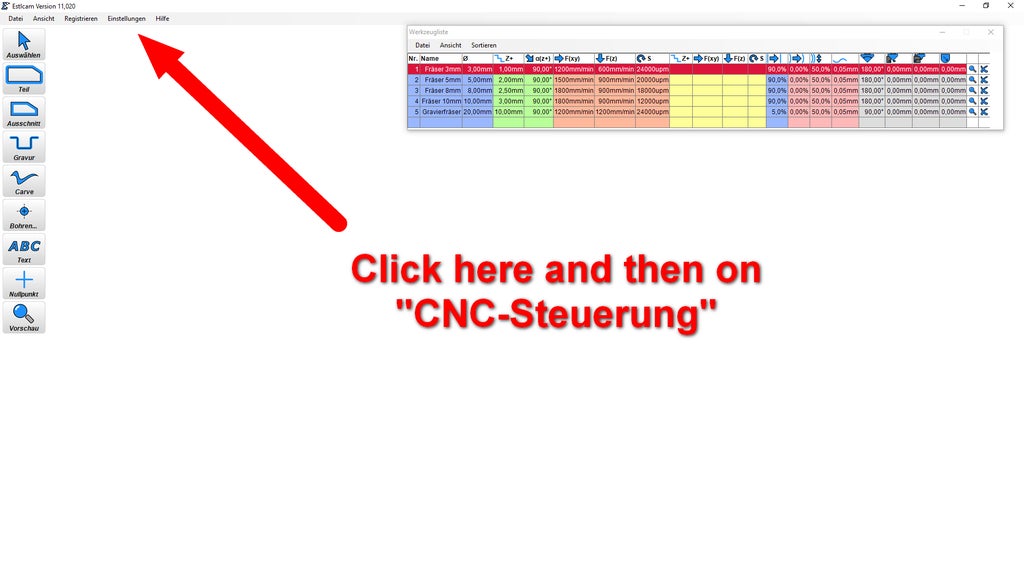
2. After that a window will open with some configurations. There you will see all the basic values for this machine. Once you have all the settings like in the picture, connect your Arduino to your computer, select the right COM-Port, click on "Steuerung-Programmieren": 
3. If the programming of the Arduino was a success, close "Estlcam" and open "CNC-Controller". Now you should be able to move your machine. 
4.Here is a video of the test-file. The test file can be downloaded at the bottom of this step. The feedrate in the testfile is 2400mm/min.

Step 23: CNC-Milled Results
Here I will show you some CNC-milled parts, which where milled on this machine. ( list will be extended in the future )

Second Prize in the
Build a Tool Contest


