

Introduction: Lab Bench Power Supply


Hi, I am Giovanni Aggiustatutto and welcome to this Instructable! In this guide we will build a variable lab bench power supply. For those who make electronics projects, the variable power supply is an extremely useful tool, which is why, sooner or later, everyone builds one. A bench power supply allows us to adjust the voltage and current on the output, to be able to power the circuits we are working on. The power supply I built has the ability to adjust the voltage from 0 to 36V DC quite accurately, and it also allows us to limit the output current. These adjustments can be made using the knob and the buttons. The display shows the voltage we have set and the current drawn by the load that we have connected. In addition, I added two USB ports to the power supply, which are very useful for powering boards such as ESP32 or Arduino, which I happen to use very often.
As always, I've also made a video about this project, that you can find on my YouTube channel (it has English subtitles).
Supplies
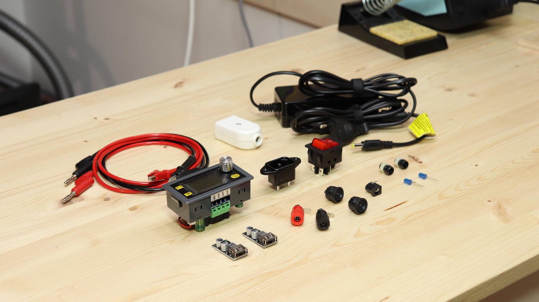
To make this project, I used:
- Buck-boost 6-36V 80W voltage regulator with voltage and current meter (link here)
- USB port step-down converter (link here)
- IEC C14 230V input connector (like the ones that are on computers, printers...)
- 230V double-pole switch with indicator light
- 19V power supply from an old laptop
- 2 sigle-pole round switches
- 2 blue LEDs
- 2 2Kohm resistors
- 2 led panel holders
- 2 panel-mount banana connectors (red and black, like these ones)
- Wires for low voltage connections
- Wire for mains voltage connections
- 14 M3x12 mm screws
- 14 M3 nuts
- 8 M3 threaded inserts
Tools I used for this project:
- 3D printer with grey and black PLA filament
- Soldering iron
- Hot glue
- Screwdrivers, pliers and other basic tools
Step 1: The Voltage Regulator


To build a bench power supply, the first thing we need is a voltage regulator. In fact, this is the circuit that will allow us to adjust the voltage on the output, which is the main function we need. It is also very useful to have a display that shows the voltage we have set and the current that's drawn by the load. The module I bought for my projects costs about 15€. Inside it has a voltage regulator that goes from 0 to 36V with an output power of 80W. It also allows to limit the output current. On the front it has a display, on which the voltage and current are shown. Voltage and current adjustments can be made quite precisely using the knob and the various buttons. Behind the module we have two output terminals to connect the load, and two input terminals, to which we have to connect a power supply. In my case I will use the power supply of an old laptop PC, which has a voltage of 19V and a current of about 4A. However, any 24V or 12V power supply should be fine, as the voltage regulator can both step up or step down the voltage.
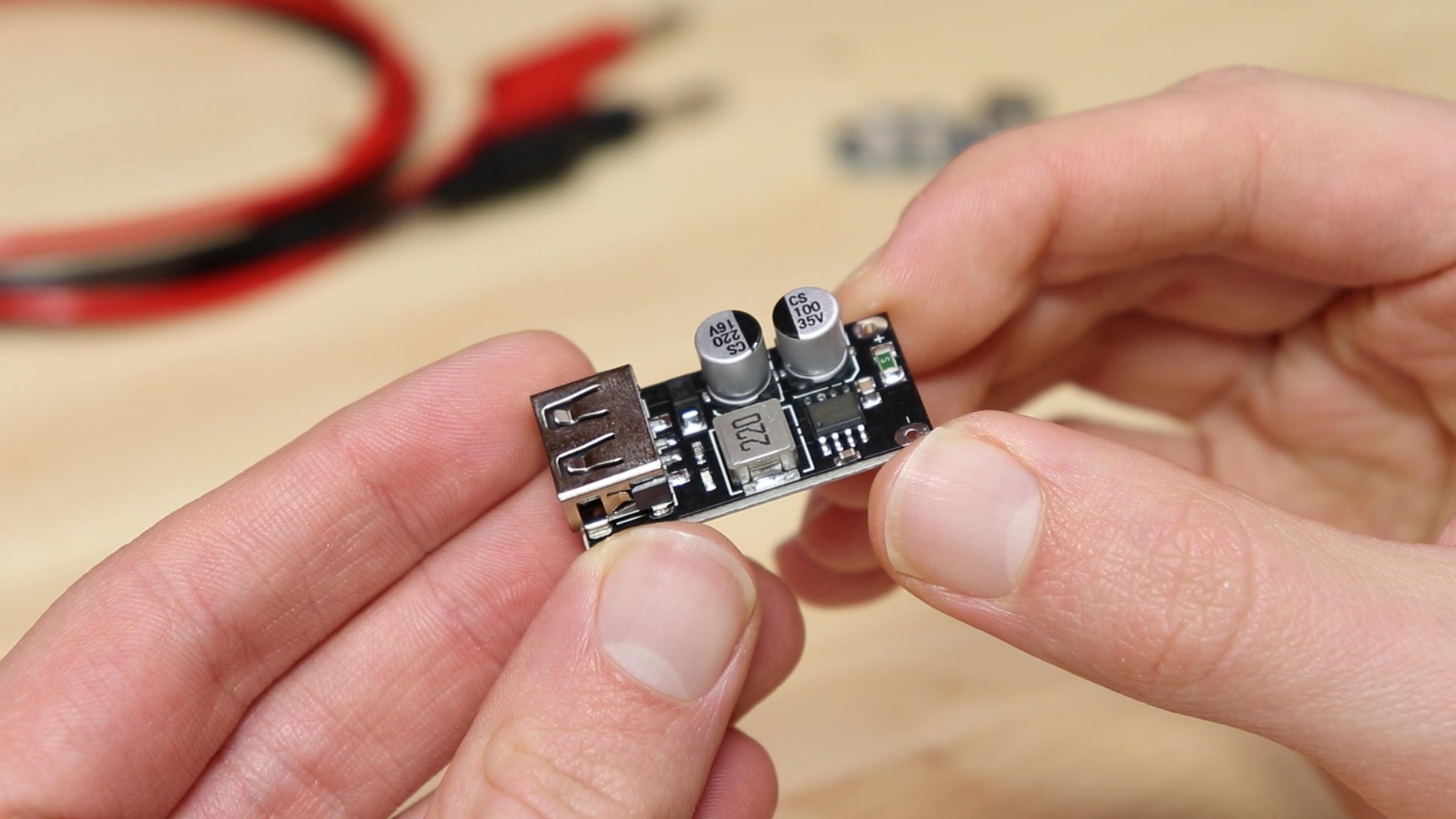
In the bench power supply I also wanted to integrate USB ports. For a very low price I found two modules that convert the voltage that is given on the input to 5V, which are provided on the USB ports. The USB ports will each have their own switch, and an LED to indicate if it is on.
Step 2: 3D Printed Parts


Now that we have all the components we can build the power supply. As always in my projects I try to take care of aesthetics and design in addition to functionality. So I spent some time designing the power supply on Fusion 360. Initially I was thinking of making the power supply with a wooden box and the front and back panels made out of aluminum. However getting a nice result was a lot harder than I expected, and I had to give up. After redesigning everything I decided to make all the parts with the 3D printer, using a combination of black and gray PLA, which in my opinion gives the power supply a great look. The STL files for 3D printing are below.
In particular, I printed with gray PLA the panels for the front and the back of the power supply, that have all the holes to mount the components. Also with gray I printed the 4 side walls. With black PLA I printed 4 corner profiles that have grooves that will be used to join the 4 walls to the two panels at the front and back. These profile will make the assembling part extremely easy and will allow us to secure everything using only 8 screws.Using black PLA I also printed 2 frames to cover the joint between the panels. The frames also have feet to raise the power supply off the table. With black PLA I also printed a grid to remove the heat generated by the electronics and two holders for mounting the USB ports to the front panel.
In the 4 profiles I put M3 threaded inserts on both sides, which we will need to assemble the whole structure.
Attachments


Step 3: Installing the Voltage Regulator


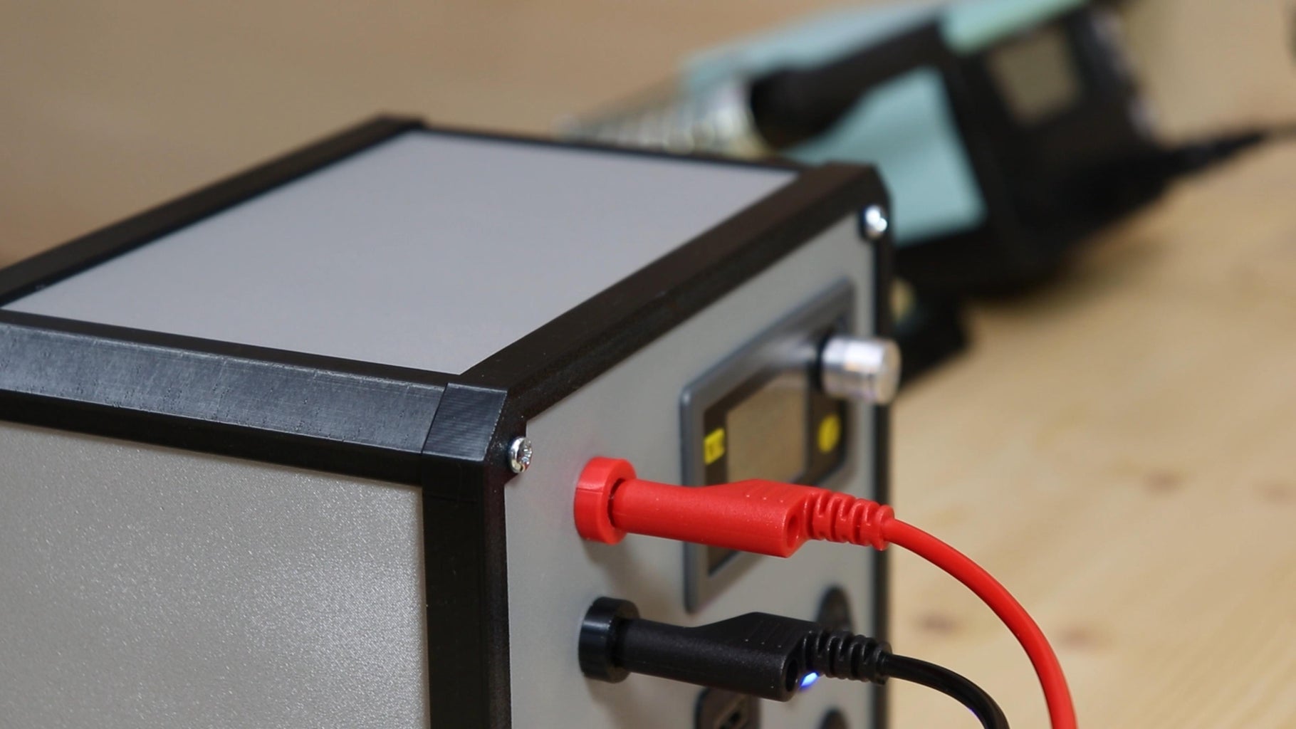
At this point I started assembling the power supply, starting right from the front panel. In the front panel I first put the voltage regulator, and secured it with some hot glue. To connect the + and - output cables I suggest to use two panel-mount banana connectors (like these ones), that can be simply screwed into the panel. However I didn't have them, so I adapted some speaker banana connectors with two 3D printed parts. In case you also want to use my solution, the 3D file for the adapter is below.
Attachments

Step 4: Installing the USB Ports


Then it was time to mount the USB ports. First I glued the two 3D printed holders to the panel, and then I glued the boards with the USB ports on the holders. Next to the USB ports I also mounted the switches that will be used to turn them on and off. For each of the USB ports I also wanted to put an LED to indicate when it is turned on. I chose two blue LEDs, and soldered a 2 Kohm resistor to the positive. Then I soldered two wires, one to the resistor and the other one to the negative of the LEDs, to power them. In order to mount the LEDs onto the panel I used two plastic LED holders.
Step 5: Main Switch and Back Panel


Last, I mounted on the panel the mains voltage switch that will turn on the whole power supply. On the back panel I mounted the mains voltage input connector for the power supply, using two M3 screws and nuts. On the back panel I also mounted the 3D printed grid to let out the heat that is generated by the electronics, using four M3 screws and nuts.
Step 6: Connecting the Voltage Regulator


At this point I could start making the connections. First, I soldered on a piece of perfboard a barrel connector to which I will connect the laptop power supply that will be used to power the whole power supply. This way we will have a central point from which to get power for all the components. I used a connector because I didn't want to cut the cable of the power supply, in case one day I will need to use it for other projects. However, if you are fine with cutting the cable of the power supply you can connect its positive and negative directly to the board. This is true also if you are using a power supply that comes with screw terminals, because you can just connect the wires to its + and - terminals.
To the board that we have just prepared I soldered two pieces of thick wire, that I connected to the input terminals of the voltage regulator. At the output of the voltage regulator I connected two more wires, that I soldered to the positive and negative output connectors of the power supply.
Below or in the pictures you can find the schematic that I followed when making all the connections.
Attachments

Step 7: Connecting the USB Ports


To connect the USB ports I used thinner cable, because the load will be smaller. With two pieces of cable I carried the positive from the power supply to the two switches that will control the USB ports. To the other pin of each of the switches I connected the positive of the corresponding LED and, with another piece of cable, the positive of the module with the USB port. Lastly I connected the negative of the USB ports and LEDs to the negative of the power supply. Where it was possible I protected the soldered connections with heat shrink tubing, to avoid short circuits.
Below or in the pictures you can find the schematic that I followed when making all the connections.
Attachments
Step 8: Preparing the Structure


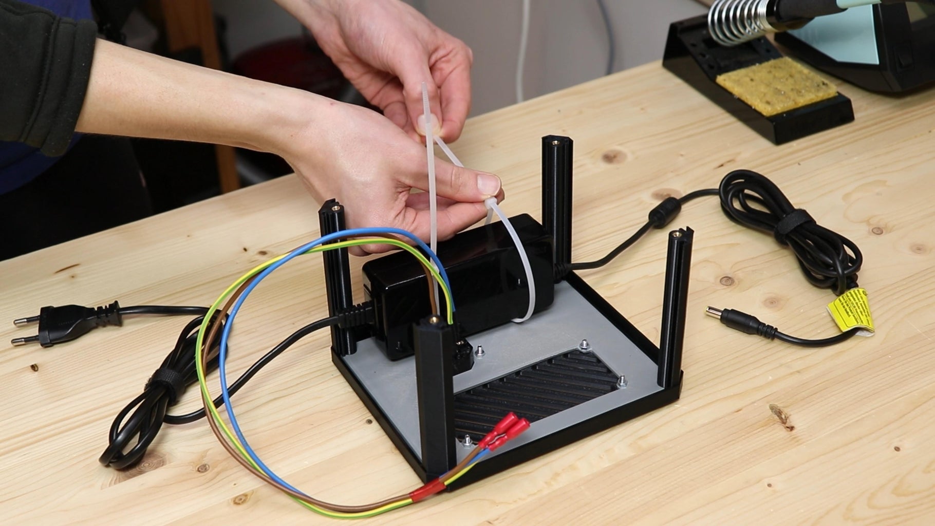
At this point we can start assembling the structure of the bench power supply. Before doing that, however, I soldered 3 wires for line, neutral and earth to the mains voltage power connector that will be on the back, and protected the connections with some heat-shrink tube for safety. Then I put the black 3D printed frame on the back panel. With M3 screws, I secured the 4 corner profiles to the back panel and the frame, using the threaded inserts I had put in before.
Then I placed the power supply on the back panel, and attached it to the hooks that are embedded in the 3D printed part with zip ties.
Step 9: Mains Voltage Connections


Now we need to make the connections of the 230V part, that includes the power connector, the main switch and the power supply. First, however, I must remind you that the mains voltage, 230V, can be very dangerous, so it is important to always be very careful and protect the connections adequately.
First, I connected the line and neutral wires coming from the power connector to the input of the main switch, using some crimp terminals. To the two output pins of the switch I connected two segments of wire, which I connected along with the earth wire coming from the input connector to a socket. To this socket I connected the power supply plug. Instead, to the output connector of the power supply I connected the circuit of the front panel using the connector we have connected before. Of course, this solution is not very elegant, but I didn't want to cut the power supply cable in case I need to use it for something else in the future. However, as I said before, if you are fine with cutting the cables of the power supply or if you are using a power supply that comes with screw terminals, you can make the connections a lot more neat.
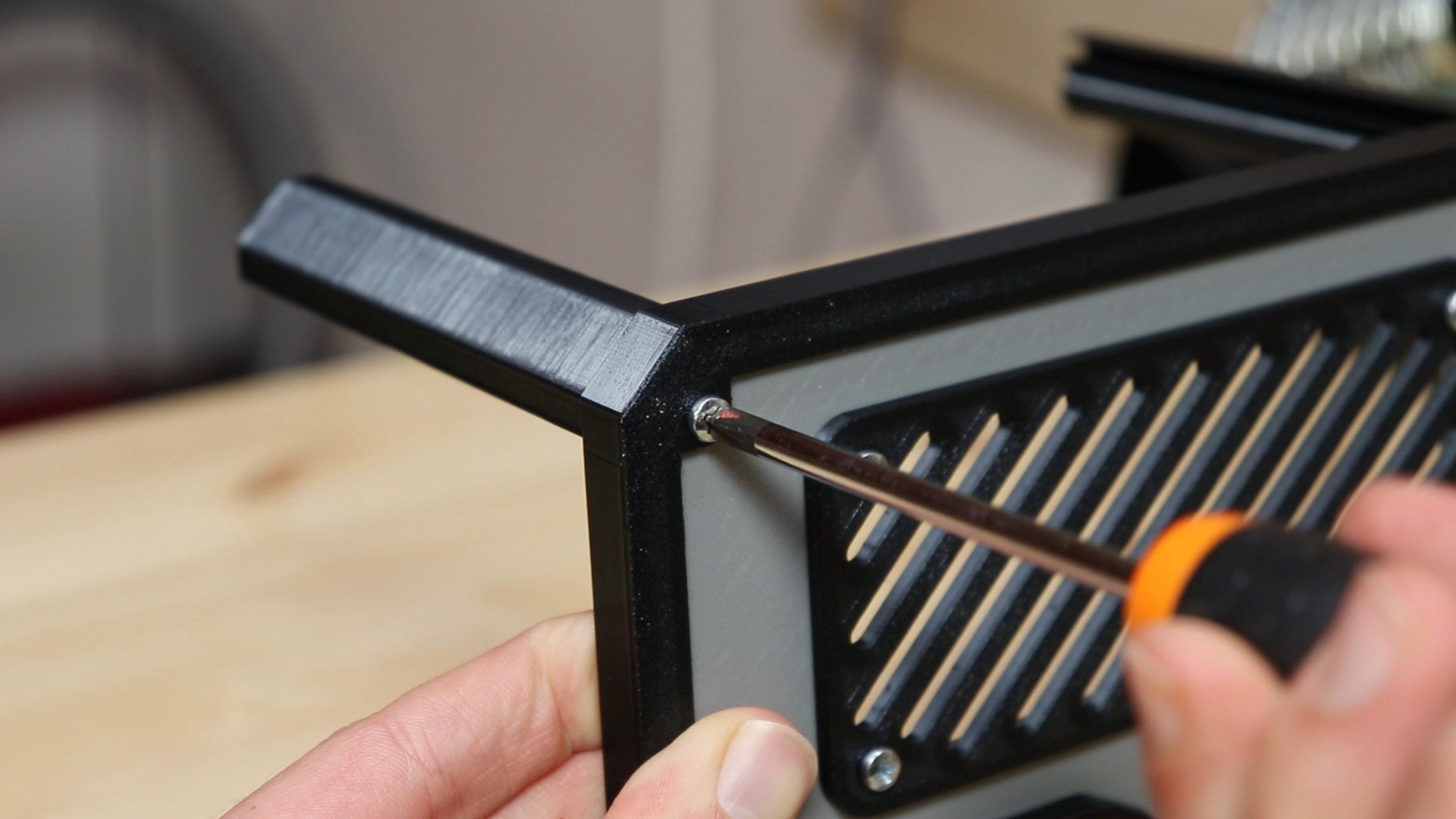
Step 10: Closing the Power Supply


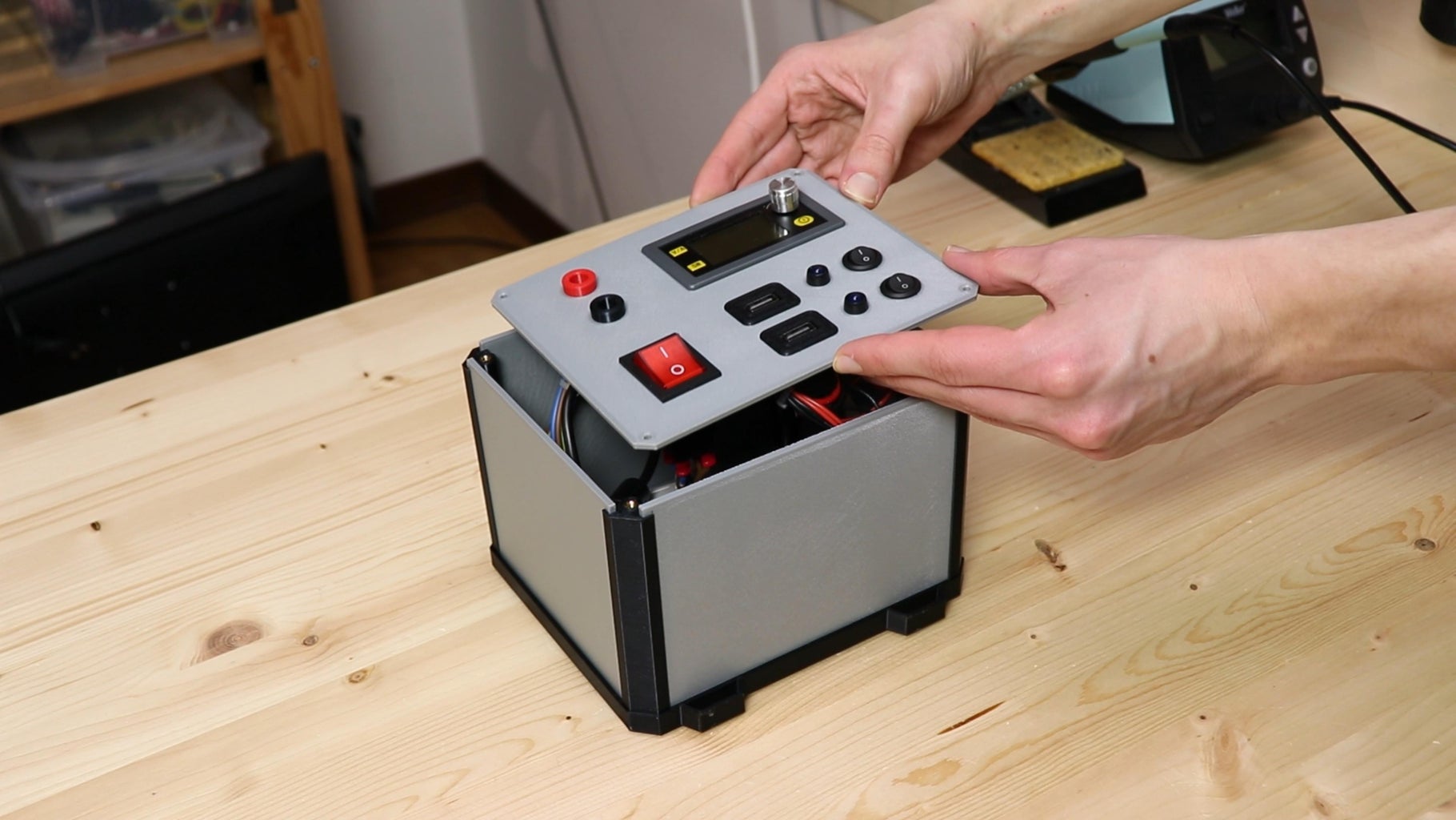
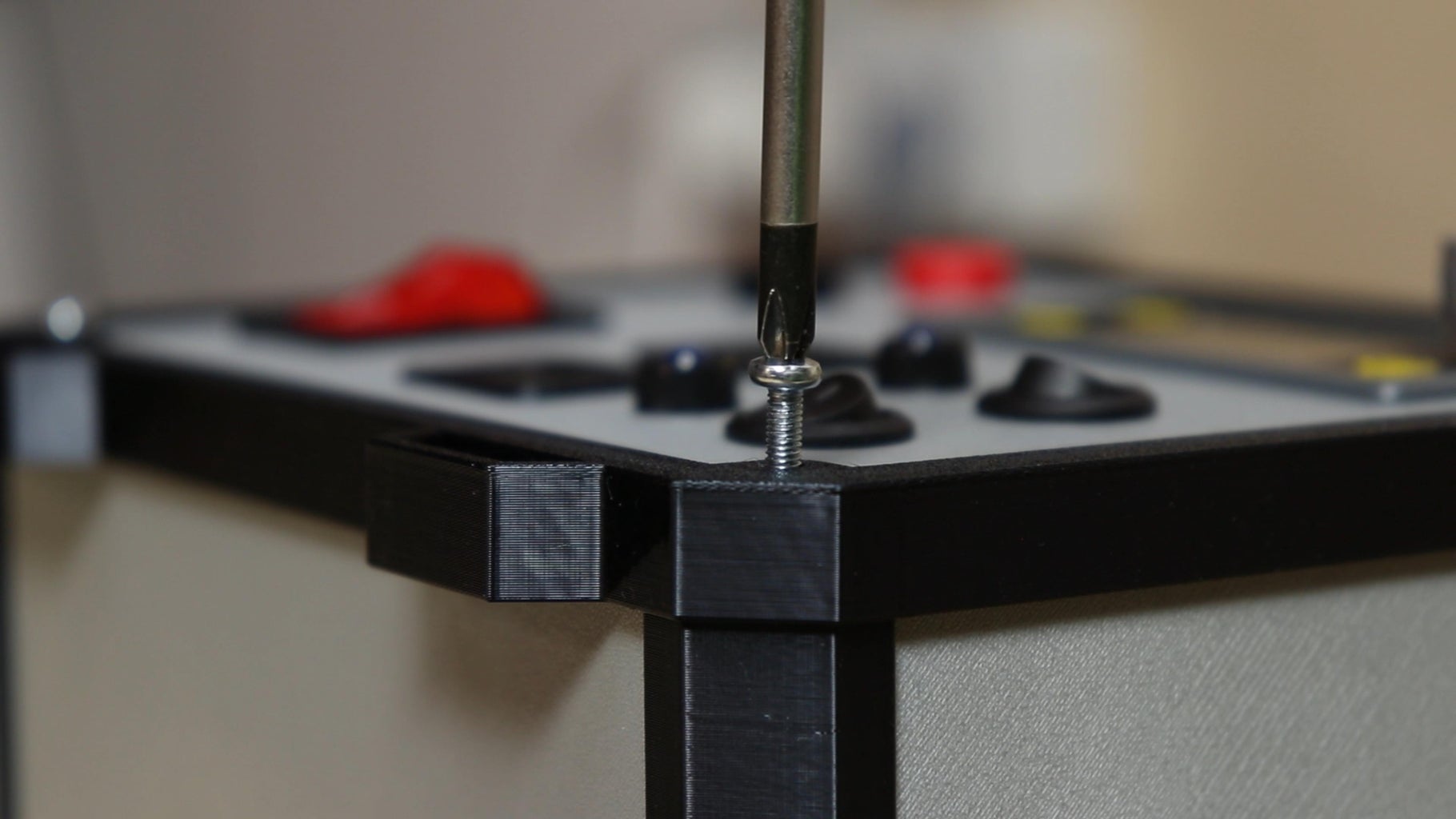
After tidying up the cables with cable ties, we can finish assembling the structure. In the grooves of the corner profiles, I inserted the 3D printed panels of the 4 walls. Then I put all the cables inside of the enclosure and closed the power supply with the front panel. Around the panel I put its 3D printed frame. As a last thing, I secured the panel and the frame to the rest of the structure with M3 screws.
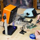
Step 11: Testing the Power Supply
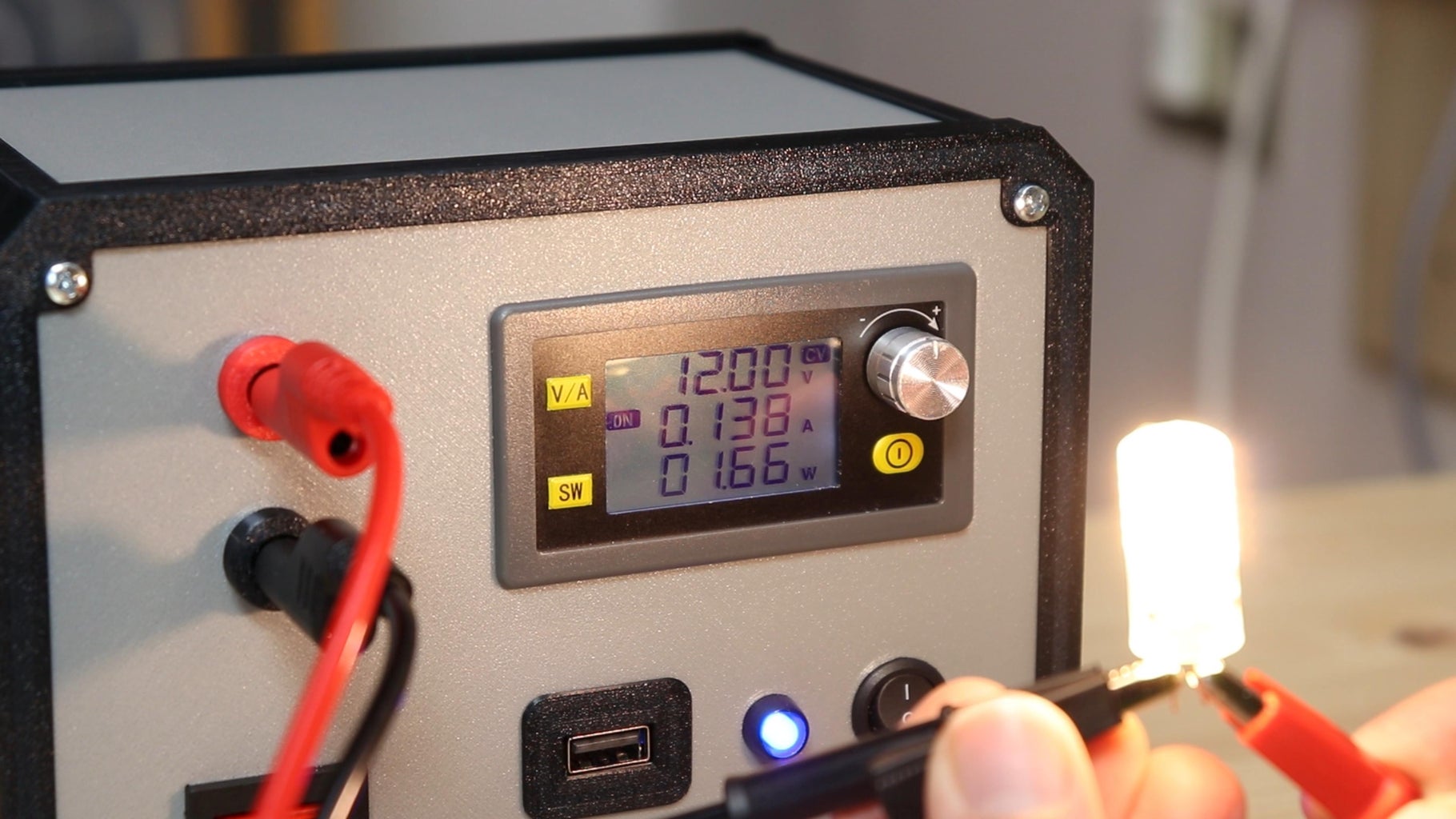


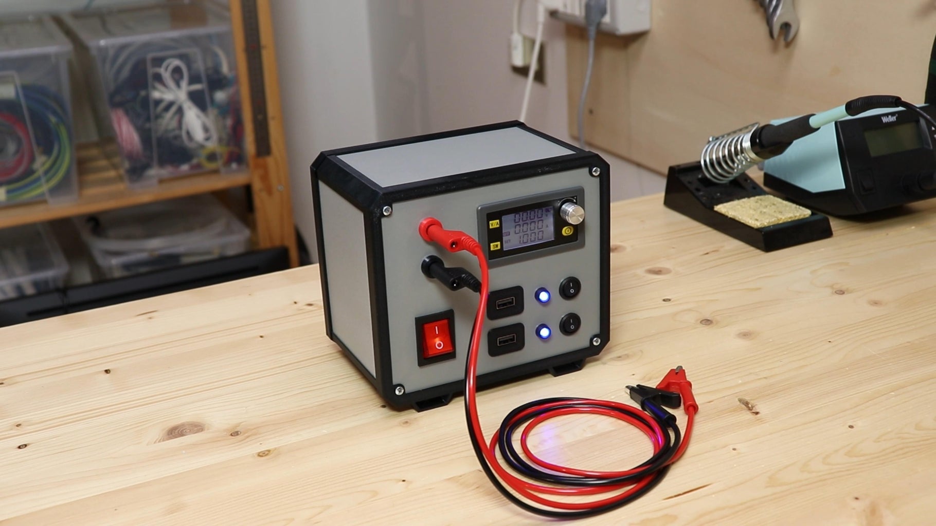
Now our lab bench power supply is finished. After connecting a power cord to the input connector on the back, I turned on the power supply. To the output connectors with positive and negative I connected two cables that have a banana plug at one end, and an alligator clip at the other. These cables will allow us to connect the load that we need to power to the power supply.
To test the power supply, I connected a 12V LED bulb to its output. After setting the voltage on the display with the knob, I turned on the output, and the bulb turned on. On the display I can see not only the voltage that I have set but also the current the bulb is drawing, which is very useful when working with electronics circuits. With a good quality multimeter I tried to measure the voltage coming to the bulb, and I was surprised to see that the reading of the multimeter matched almost perfectly the one of the display of the voltage regulator. I also measured the current, and again the display reading was the almost the same as the multimeter's reading, so even though the voltage regulator is cheap, it is accurate enough for most use cases. The function of limiting the output current also seems to work well, and it is very useful for protecting the voltage regulator in case of short circuit between the output terminals.
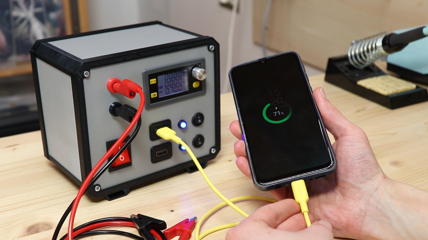
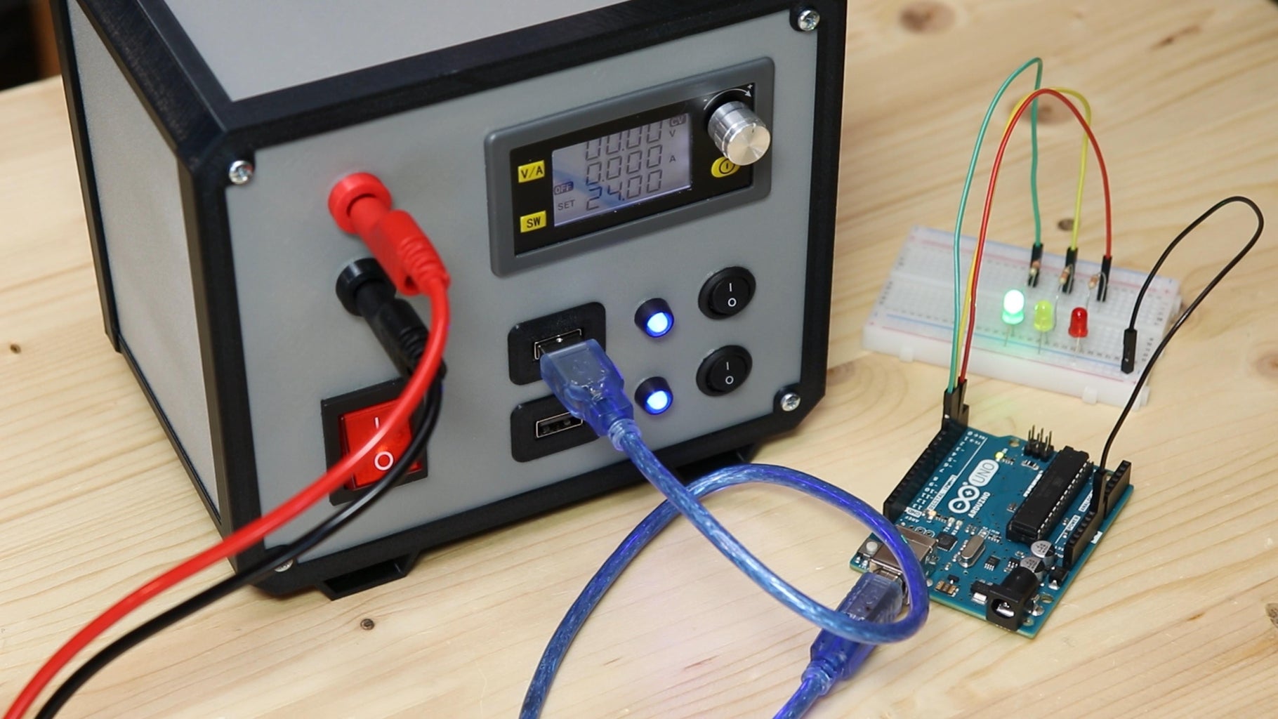
With the USB ports I can both charge a phone or power boards such as Arduino or ESP32, and the fact that they can be turned them on and off with the two switches is very convenient.
Step 12: Finished!

Overall, I am very satisfied with how the power supply came out, both functionally and aesthetically. I hope you found this guide interesting and maybe useful. To see more details about this project, watch the video on my YouTube channel. Bye!


