

Introduction: Mini Drill Press With Variable Speed


I recently got into PCB etching to bypass the nightmare of soldering on perfboards or ordering PCBs online with 20$ shipping fees. A lot of trial and error was required, but I have been getting consistently usable PCBs until the moment came to drill the holes. In most circuits there's at least 2*N amount of holes where N is the number of components. Add in an IC or a few transistors, and you end up with 30+ holes in a tiny board.
Copper clad boards that are used for PCB etching are pretty easy to drill through, but this process requires a lot of precision. If you have a double layered PCB you have to makes the holes absolutely perpendicular. It is extremely tough to do so without a drill press and I felt that pain.
A solid Drill Press costs about 80-100$ on Amazon. Alternative to that, you could buy a Drill Press Adapter for Dremel, which costs about 40-50$ but you have to sacrifice your Dremel to it, or screw it in and unscrew it every time you want to use the Dremel. So I went for the other alternative, to make my own.
In this Instructable I will share with you how I made this 3d printed Drill Press with adjustable speed control. This cost me 20-25$ to make, not counting the 3d printer's price of course.
You will of course need a 3d Printer to make this, but there are wood working alternatives that you could look up online.
*SAFETY SHOULD BE NUMBER ONE PRIORITY. It is not worth losing a finger by using an improperly built drill. So if you decide to follow this Instructable, make sure to double and triple check for any safety issues. Safety goggles and gloves are also important.*
This Instructable is going to be divided into several parts, here is a breakdown:
1) Watch the video! Watching how moving parts go together is easier than imagining it in your head with descriptive words.
2) 3D Designing and Printing of parts.
3) Schematic and how the circuit works.
4) Testing the Circuit.
5) Soldering the Circuit.
6) Assembling and mounting the whole build.
7) Troubleshooting tips, and improving it!
8) Files for the project (3D Model and PCB).
Supplies


Circuit components:
- Resistors : 47k, 2k, 2k.
- Potentiometer: 100k
- Capacitors : 0.1 uF(1), 0.01 uf(1), 10 uF (1)
- 555 timer IC : Link
- 1N4148 Diode (3)
- DC Barrel Jack Connector
- 12V Power Adapter (Could modify and use laptop chargers and other AC-DC adapters)
- IRF510 N channel MOSFET or any other N channel MOSFET with good current rating.
- SPDT Toggle switch
Parts for Drilling:
- 12 V DC motor
- Chuck for Specific Motor
- Drill bits
I bought these three as a set, from Amazon for only 11$. I am quite satisfied with the quality of it, so here's the link for anyone interested.
Mechanical Components:
- 4.5 Inch long 3/8 Inch diameter Hex Bolt (3)
- 3 Inch long 3/8 Inch diameter Hex Bolt (1)
- 3/8 Inch inner diameter Hex nut (8)
- Size 6 (3.5mm Diameter maybe?) Machine Screw (7)
- Nuts for the Machine screws (10)
- Extension Spring (optional), could be replaced by a rubber band.
Testing supplies:
- Breadboard
- Power supply
- Jumper Cables
- Multimeter
- Oscilloscope is helpful, but not needed.
Prototyping:
- 3d Printer
- Soldering Station
- Hot glue
- Super glue
Circuit Prototyping:
- Printed Circuit Board from JLCPCB or PCBway or homemade one.
If PCB printing is not an option, then consider the following:
- Perfboard
- 8 Pin IC socket (1)
- Wires for connections
- Electrical tape
- Soldering Helping hands
Step 1: Watch the Video
Watch the video, it shows the full building process, the drill working and my hands.
Step 2: 3D Model

On the internet you are never the first person to face a problem. And when exists a problem, someone most likely made a solution.
So before building any 3d design for something it is always a good idea to check for existing models, for either ideas or inspiration.
There were quite a few 3d printed Drill press models on Thingiverse, and this one in the picture was really great. However I wanted to add some more functionalities to it such as a depth stopper, a proper circuit based control. But most importantly, most of the mechanical parts used in the build were not available to me in the proper sizes.
Thankfully 3d modelling is quite easy and accessible, so I chose to modify the STL models rather than ordering those parts online.
In the next part I will go over how I went about modifying STL files, and how you could do the same on Fusion 360. If you are already familiar with the process, skip the new few steps.
And here is the link to the original build that I am remixing: Thingiverse
Step 3: Editing STL Files in Fusion 360


The 3d Printing workflow goes somewhat like this:
3d design -> STL -> Slicer -> GCode -> Plastic Mess.
Most 3d files online are STL files, which describe only the surface of the model, not the geometry used to create it or the underlying sketches or anything. So you can not just open up the STL files and make fun of how inefficiently the designer made the model.
What you can do instead is take the STL file, convert it into Mesh and then use that Mesh to recreate a solid object. Some features of the model is lost in this process, but if you want to modify a simple block then not much is lost.
This is how I do it on Fusion 360. I open it up first, then go to Insert -> Insert Mesh -> Select the STL file you want to edit.
Then click on the mesh, and go to the Mesh tab -> Modify -> Reduce.
After that, click on Modify -> Convert Mesh. This step will convert it into a solid and you can model and edit it like you would any regular 3d Model, except sometimes the planar faces would behave erratically and have a full meltdown when you try to do a simple Extrude.
But anyway, what I did for most parts was measure the bolts and nuts that I had, and edit the threads and holes on the 3d Model accordingly.
Step 4: 3D Design and Printing


So here are all the 3d parts after designing or modifying them. I then printed them out with the my 3d printer. Only the base plate couldn't fit flat on my Monoprice Select Mini 3d printer, so I printed it upright.
Remember when printing 3d parts that could have mechanical stress upon it:
Compression force across layers of a 3d Print is okay.
Pulling force across layers of a 3d Print is not okay.
Keep that in mind in deciding printing orientation while slicing your 3d Models for printing.
Step 5: Schematic


Here's the schematic of the Motor's speed Controller.
This is a pretty simple circuit.
It uses the 555 timer IC to generate a PWM signal of fixed frequency, but variable Duty Cycle, which can be adjusted using the potentiometer. The duty cycle is the ratio between Time High and Time Low of the output signal. Time High (T1) and Time Low (T2) is based on the potentiometers resistance, the value of the fixed 2K and 47K resistor and 0.1uF capacitor. By changing the potentiometers resistance, the resistance between the Capacitor and VCC changes, which changes the charging time of the capacitor, causing T1 and T2 to differ, changing the duty cycle. The internal operations of the 555 timer circuit is described in details in this tutorial by Skinny R&D on YouTube: Link.
The output of this timer circuit connects to an N channel MOSFET which acts as a switch to power up the motor. So essentially when the output of the 555 timer has 20% duty cycle, the motor would be on for 20% of the time, and thus would run considerably slower than with a 90% duty cycle. You might think that this is a waste of money, that using a variable resistor to do this would be much better. Well, the resistor would heat up enough to fry eggs, and simply reducing voltage to control motor speed doesn't work too well. For example a 12 V motor won't be able to run at all at 2V, but with 17% duty cycle this circuit can run considerably slower than its full speed.
Moving on, the motor has a diode connected across its terminals, and that is to protect the rest of the circuit from the motors inductive kickback. Every inductor or loop of wire would produce a massive reverse voltage spike when suddenly cut off from power. The diode provides a safe path for that voltage to go through, thus not damaging the rest of the circuit.
Enough circuit theory and college student's electrical explanation. Time for building again.
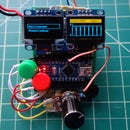
Step 6: Test the Circuit


I built the circuit on a breadboard and confirmed that the output signal was properly adjusting the duty cycle.
After that I connected the motor and tested it out.
I had to switch out multiple resistors and parts of different values before this one worked, but I am not sure why the other variations worked. It was drawing close to 300 mA with no load on the motor at full speed, but I would assume that with a Drill Chuck on its head and a PCB to drill through, the current draw would rise above 1 or 2 Amps. Make sure your 12V adapter is suited for such current loads.
Step 7: Make It Permanent: PCB Edition


Since it worked on breadboard I moved onto making it permanent. I designed the PCB on EASYEDA. I decided to be a little ambitious and make it double layered, but I think single layered would be more consistent and reliable, but tougher to route.
I followed the regular PCB etching process, print traces on a paper, transfer using heat, fix missing or broken traces, then etch in an etching solution and finally getting to soldering.
I know the holes are terrible, but hopefully after this build is done, I will never have to see such holes on a PCB ever again.
There are 4 big holes on the PCB which are 3.5 mm each. These will be used for mounting to the Slide. The top holes are 20 mm away from each other. The bottom holes are 20 mm away from each other. The top and bottom holes are 40 mm away from each other.
Anyway, after soldering on all the components, I plugged in power and it worked, so I moved onto the next step.
Step 8: Assemble: Body


This step is a bit hard to explain in words, but I hope the pictures are worth a thousand words. Follow them to see the sequence of how the parts are assembled together.
Insert two 4.5 inch Hex bolts through the base plate. Tighten with nuts.
Screw in a nut to one of the bolts and insert the Depth Stopper.
Take the Lever and insert a 4.5 inch Bolt through it. Tighten with nut. Insert another nut and washer. Pass the bolt through the mount and gear and hold it in place with washer and nut.
Screw in a 3 inch bolt through the Lever, to create, well a lever.
Use super glue to keep the non moving parts where they are supposed to be. Watch the video for better understanding of how this step should be done.
Step 9: Assemble: Slide and Motor


Insert the Chuck onto the motor and tighten the Allen screws on the side of the chuck.
Take the slide and insert four machine screws and tighten with nuts. Mount the PCB onto the 4 screws and tighten with nuts. Insert the motor into the motor bracket and tighten the bracket using machine screw and nut.
Make sure to connect the spring to one of the screws holding the motor bracket in place. This spring will be used as a force to stop the Drill from always flopping down.
Step 10: Assemble the Mount and Slide


Finally slide in the Slide into the Mount. Attach the spring to the Mount using a screw.
And at this point you are pretty much done. Make sure to adjust the ring for Depth so that you don't end up drilling through your work surface.
Now place a PCB under the drill. Connect the jack. Toggle the switch, crank up or down the speed and go about drilling through those holes.
Step 11: Troubleshooting and Safety
Troubleshooting:
Here are some common problems you might face that I faced, and what I would suggest if I didn't have the energy to help you, but still wanted to feel like I did:
1) My IC chip is getting too hot and not giving a proper output: You burnt it. 555 timers are pretty cheap, just chuck that one out and start new.
2) My IC Chip is giving a proper PWM signal but the motor isn't getting slower or faster: Change the frequency of the timer circuit's output by changing the Caps or Resistor values.
3) Circuit's not working and I know the chip isn't the issue: Start from the beginning and check every single connection. Take it apart and build it again. Capacitors could burn out, watch out.
4) Motor's shaking too much and it's not spinning in a perfect line: Motor shakes when the spinning part moves around and not in a circle. Basically something connected to the motor isn't in a straight line. Take apart the chuck and mount it again. If you mount it straight, it will not shake.
Safety:
When I started the motor up, it started shaking violently and threw the Chuck across the floor.
I later realized it was because I tightened one side only, making it tilt in one direction and causing an imbalance in the rotation and making it shake. It could have happened when I inserted the drill bits, and I wouldn't have been typing this Instructable, at least today.
So do yourself a favor, do not take unnecessary risks. You will have no one but yourself to sue in case of an accident, and that will not be fun.
Wear safety goggles. Drill bits from Ebay and most Amazon sellers are notoriously fragile. Your garden squirrel can snap it in half with their hands.
Step 12: Files and Parting Words
Here are all the files for 3d printing. If I upload the files on Thingiverse, I will include a link here so you guys can check that out if you want.
Instructables editor doesn't allow Zip files so I will just include a link to the Gerber files here: Gerber
Anyway, if you managed to make it here, thank you for reading!
If you managed to skim to here, thank you for skimming!
If you managed to jump to here, thank you still!
See you on my next build.


First Prize in the
Build a Tool Contest


