

Introduction: Multifactor RFID and One Time Password Door Access Module


RFID access to doors is great, but what if the tag gets lost or stolen? It gives any possessor unvetted access.
I've used RFID tags for a long time but the inherent security of standard cards is the same across most systems and many tags can be duplicated with simple tools. Only the expensive commercial systems can't be copied or employ their own multifactor system such as a pin and/or fingerprint in combination with the tag being read.
A step further is to use a Time Based One Time Password (TOTP) in combination with the relatively low security of the RFID to be able to gain access.
Most of you probably use multifactor authentication in some form in your lives already - For example when a bank sends you an SMS code to authorize a transaction or logging in to some websites. For example, Facebook can be configured to force you to enter a special code generated by your phone when logging in to your account from a new computer.
Inspiration for this project came from this Instructable published by Adimiller. Employing a simple one time password is pretty good security but their system has some disadvantages. I came up with my own version but taking it to the next level by adding some extra hardware to make it multi-factor with RFID and some backup features.
Supplies


The core components of the system are:
ESP32 Module AliExpress
DS3231 RTC AliExpress
TTP223 Capacitive touch keypad AliExpress
A 26 bit Wiegand RFID reader of your choice (125mhz or 13.56khz) AliExpress and compatible tags
Components for an output - i.e relay module or FET/transistor board (or use my PCB)
2 X WS2812b LEDs of your choice.
0.91" 128X32 OLED Display AliExpress
This Instructable is more about the code, and leaves the maker to decide the best options for them to implement it in hardware but I have developed a relatively simple PCB suitable for this project.
If using my PCB, you will need some additional components:
10k SMD Resistor
5v Regulator Aliexpress
AO3400 Mosfet Aliexpress
M1 1N4001 Diode Aliexpress
Header pins etc.
Also note that the PCB design is using a specific type of ESP32 module and they are not all the same - Make sure the pinout matches what you buy.
The PCB design provided is slightly different from the one in this Instructable - I have made changes to it since as this board was designed for an earlier version of this project but assembly should be pretty straight forward.
What about Wiegand 34 Readers?
You could do it but probably not much point. My custom code converts the 26 bit code to a 32 bit code, ignoring the actual site code etc (the code read is not what is printed on the card). If using 34 bits, you'd have to change the code to 40bit (5 Bytes) and modify the code as needed (EEPROM locations/allowances etc.), it would not be trivial but not impossible either, but with no benefit.
What about a classic keypad?
Currently untested and would not work without changes to the code but can be done.
What about the Blue 16 Key keypads?
I started with one of these but if you want a 1-9 + A-D keypad, then you need to have some sort of overlay on it. I tried with a printed (paper) overlay and then covered with a thin clear plastic sheet but it got random phantom presses and was hard to ensure you pressed the right button. The one linked to is larger than the blue ones, so there is a bigger gap between buttons and is pre-labelled.
Step 1: Connecting It Up
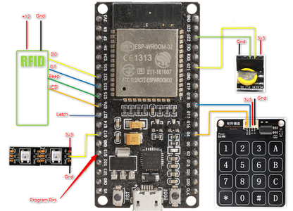


RFID Reader
D0 ->D32
D1 -> D33
Beep - D25
LED - D26
Power -> +12v (some readers will work down to as low as 5v)
Gnd -> Gnd
DS3231
+ -> 3v
G -> Gnd
C -> D22
D -> D21
OLED
+ -> 3v
G -> Gnd
C -> D22
D -> D21
This connected to the top of the DS3231 in my photos from the old PCB design
WS2812B
Vin -> 3v
Gnd -> Gnd
Din - D12
Keypad
Vc -. 3v
G - Gnd
SDO -> D5
SCL -> D4
Notes:
The keypad is NOT I2c despite the pin labelling
In this demo I am using an external beeper as the RFID reader I am using does not have a controllable beeper (but most do)
Connect the ground of the 12v to the ground of the ESP32. For the moment we will be powering the ESP32 from USB but later you may want to include a 5v regulator (as is on my PCB) to utilize a single power supply.
Step 2: Program the ESP32

Installing Arduino and configuring libraries/environments is outside of the scope of this instructable so I will not cover it here. There are plenty of other guides to help you if you need it.
You will need to Install the ESP32 Arduino Environment - Instructions
Add libraries:
Base32 (Manual install)
FastLed (Arduino Library Manager)
ErriezTTP229 (Manual Install)
RTCLib (Arduino Library Manager)
ezTime (Arduino Library Manager)
u8g2 (Arduino Library Manager)
Set your Parameters
Open the included ino file and set your Wifi SSID, password and hostname for the device:
Set your own personal override code as well as it's length. This code is used as a failover if you can't get your OTP for some reason. Make it long and preferably with letters (limited to the ones on the keypad) and set the length of this code below it.
Set your time zone based on this list - This makes the display show in your local time rather than UTC, however all OTP calculations are based on UTC and it is not relevant to the operation if this is set wrong.
You may need to change he option for 'beepOn' and 'beepOff' If your beeper is active high, but most are active low. If it starts beeping as soon as you power up or you are using an external (active high) beeper, invert these values.
Program away!

Step 3: Verify Internet Connection and Time


On boot, the device will attempt to connect to your designated Wifi. Assuming a successful connection it will attempt to get the time from the internet via pool.ntp.org and then use this time to set the RTC time.
The RTC is used as the 'truth' for all OTP functions. Only the time on the display is using the internet time (via ezTime) as this is simpler to use for that function and allows for your timezone to be used so that the display can show your current actual time.
The system will automatically always make sure the RTC is accurate as long as it has internet access.
The LEDs work as follows:
Led 0 - RTC Status
- Orange if the system is relying on RTC for it's current time, i.e immediately after boot.
- Green if ezTime was able to connect to the internet, get the current time and sync to RTC
- Red - There is an issue with the RTC, system inoperable.
Led 1 - Wifi Status
- Red - Unable to connect to programmed Wifi network
- Orange Flashing - Attempting to connect to Wifi
- Orange- Connected to the Wifi but unable to sync time with pool.ntp.org
- Green - Successfully connected to Wifi and time data is being received ok.
Step 4: Adding Tags
After first programming with Arduino, there will be no valid tags programmed in.
Programming tags is accomplished by holding down the program button while reading a tag. This will then add the tag to EEPROM as well as generating an OTP secret that will be used for adding to your device. The code is printed over serial at 57600 and is used to add your code in an authenticator app on your phone (Google Authenticator, Microsoft Authenticator, Authenticator Plus etc) or using a program such as WinAuth in windows (Demonstrated, but impractical for this purpose - Good for a backup).
Copy the URL generated into a browser to give you a QRCode that you can scan with your phone to easily add it.
Tags are added sequentially and the process will overwrite tags if the system is rebooted between tag programming. It is designed as a low key count system where this is not an issue to program all tags at once. There is currently no implementation for removing/disabling tags. Perhaps with the master code and entering a tag number to delete could be implemented but my systems only use one or two tags so I have not bothered with this.
Another option would be to use a web interface to manage tags but this can leave the system open to exploitation. Perhaps in revision 2....
Step 5: Testing
After programming in your tags and using the 'secret' or QRCode to add the OTP to your device, you should now be able to swipe a tag and enter the OTP to gain access.
You can also use/test the master access code by pressing '*', reading any valid tag and then entering the master code on the keypad.
When access is granted, pin D27 will go high for 5 seconds. This can be connected to a relay module or FET to switch a door strike or other locking mechanism of your preference.
If using my PCB, a door strike or relay can be connected directly to the 'Lock' header as it has a FET to drive it and flyback protection diode already onboard.
Step 6: Going Even Further

This Instructable is actually a step down from what I implemented for my own use. The reason I created this slightly cut down version and not the one I am actually using is because it utilizes a Nextion 3.8" touchscreen which is expensive (About $50 alone) but it does offer some great benefits such as being able to display a QR code for adding into an authenticator app and being able to show Wifi signal strength etc. It's much better and way cooler, I just felt that this was less accessible to the greater community and it also requires a separate application for programming the screen which is not overly friendly for sharing the configuration and adds an undesired layer of complexity. If this interests you, let me know.

Runner Up in the
Microcontroller Contest


