

Introduction: Nadine : the Tweeting Grill


When cooking on a charcoal BBQ, knowing when food is done can be difficult. I usually take a small knife and cut a slit at the thickest part to get a peak at the inside color. While looking to buy a new grill, I came to learn that knowing when food was done was all about knowing the internal temperature of the meat.
I eventually decided to solve this problem with a fun summer project, modding a grill to monitor internal temperature. I also added something extra, a social aspect. If I needed to be alerted of the food being done, why not make it public, or at least amongst friends? This is how a grill was born into the IoT universe, a grill I came to name Nadine.
Nadine has her own twitter account, which the chef can follow as well, so everyone knows when the food is at the perfect temp and ready to be eaten. I built a control box that has ports for temperature probes that you can use to monitor the internal temperature of your meat as you grill or the inside temperature of the grill itself. An Intel Edison is programmed to keep track of and display the temperature on a LCD screen. When the selected temperature and level of doneness is reached, it tweets out and displays that it's time to eat!
This Instructable assumes that you have prior knowledge of the Arduino platform and basic electronics.
Step 1: Materials

Most of the materials go to build the control box, which the temp probes plug into and where you can read the temperature and control the settings. I built my control box with 4 temp probes and 2 sets of control knobs, one set for each pair of probes. This is because I will be adding some external hardware later on to expand my inputs. We will be making a control box with 2 temp probes and 1 set of control knobs.
Materials
If the links are parenthetical, that means that's what I went for, but you can choose any kind you like.
[1] Charcoal grill (mine is a modded Char-griller Smokin' Pro)
[1] Edison with Arduino dev board
[1] Grove Base Shield - this can be omitted by connecting the LCD screen to the I2C bus through A4 and A5
[2] Replacement thermistor probes for digital thermometers
[2] Knob covers (Large Fluted Cream)
[2] SPDT switch (DPDT stomp switch)
[1] Rocker switch
[2] LEDs with chrome holders
[6" x 6"] 1/8" clear acrylic sheet
[9] 10K Ohm resistors
[7] 1K Ohm resistors
[2] USB cables - Type A to micro-B
[1] Project enclosure 8"x6"x3"
[1] Digital thermometer
[3"] of double sided foam tape (for mounting Edison in project enclosure)
Hookup wire
Paint (if you want to paint your grill and match the control box to it)
The below brand is what I chose, check out more paint brands in the "Paint Grill" step.
[1] Dupli-Color Grey Engine Primer
[3] Dupli-Color Detroit Diesel Alpine Green
[1] Rust-Oleum Plastic Primer (for enclosure box)
Access to:
Soldering iron
Dremel with cutting wheel attachment
Ruler
Printer
Drill with various drill bits
Wire strippers, cutters and pliers
Laser cutter (used to cut acrylic know selectors... it's not absolutely necessary)
General hand tools, depending how much you want to mod your grill
Step 2: Research on Temperature

My favorite part of a project is the research part which includes geeking out on design aesthetics and diving into new topics. I like to think this project has made me a bit of a grilling master, or master-in-training. I knew nothing of grilling, so I feel I've learned a bunch. This project is built upon the internal temperatures that different meats should arrive to that deem them safe to eat or their optimum flavor and texture.
A lot of my research was done on amazingribs.com, run by a fella named Meathead. This website goes into depth on direct and indirect grilling, what kind of thermometer you should purchase and what internal temperature meat should be cooked to. The meat temperature chart, available here for purchase, is the main reference I used to program with. Meathead knows his stuff! Another article I found useful and interesting was Parts to Repair, Modify and Upgrade your Grill or Smoker.
Notes On Choosing Temperatures
When programming this project, I skipped pork altogether because I don't eat much of it. I also broke sausages away from burgers, even though they are cooked at the same temp since we cook sausages regularly at our house and burgers should really be their own BBQ event. A veggie setting was added too, I love grilling vegetables. With veggies, instead of monitoring the internal temp of the food, you want to know the inside temp of the grill. This can be done easily a couple of ways which is gone over in a later step. Below I've listed the temperatures I programmed to the kind of food. Keep in mind that the USDA recommended minimum temperatures are higher than some listed here, so if you want to go by those check out the chart linked to in this step.
/////Beef, Lamb, Venison, Steaks, Chops, Roasts
Rare = 120° - 130°F
Medium Rare = 130° - 135°F
Medium = 135° - 145°F
Medium Well = 145° - 155°
Well = 155° +
/////Sausages
158° - 160°F
The temperature climbs quick at times, so it's good to create the alert a few degrees before reaching the desired temperature.
/////Chicken and Turkey, whole or ground
165°F
/////Burgers
158° - 160°F
Use the beef setting on the control box if you want rare or swap the above temperatures with the beef ones in the software.
/////Ribs or Brisket
190° - 205°F
Cook at a slow and low temperature of 225°F
////Fish
130° - 145°F
////Veggies
325° - 350°F
This temperature is inside the grill, not the food. It can be read when the probes are placed in a hole drilled on the top of the grill.
Step 3: Drill Holes in Top of Grill


There are all kinds of mods you can do to your grill. Drilling holes in the top of the grill is the only mod that I deem essential for this project, since being able to read how hot the grill is when the lid is closed can be important. The other mods in the following two steps are optional.
Drill Holes in Top of Grill
Many of the stock temperature gauges that come with grills and smokers are inaccurate or placed at the very top, which isn't the best place to read the temperature from. The temp at the top of the grill will not match the heat that is at the level of the grates. The temperature ultimately depends on where the coals are placed, how it's built and the air flow.
By drilling two holes in the top of the grill, a temp probe can slip in and sit there while it monitors the heat. Drill the holes close to where the food will be sitting on the grilling grates.
For my grill, that meant 3" up from the lower edge and 6" from the sides. Using a 3/16" drill bit was perfect for the temperature probes I had, some are slightly thicker or thinner. Grab ruler and measure the diameter of your probe and pick the appropriate bit.
An alternative to this, which I did not do myself, is to make or buy a probe clip that attaches to the cooking grates. One can be easily made by creating a ball of tin-foil, sculpting it around the temp probe and positioning it on the grates.
Step 4: Remove Temperature Gauges (optional)

Most of the temperature probes that come with grills won't give you much of an accurate reading. Decide whether you want to keep it installed or not. Mine popped in a large pre-cut hole on the top of the grill, held in by a piece of hardware on the other side. I chose to remove it because I was on a mission to beautify the grill and deemed it unnecessary.
Once the gauge is removed, the hole left will need to be covered. I found my cover while perusing a flea market when I found some metal belt buckles that had names on them, Bob, Sue and Nadine. Nadine seemed perfect to name my new grill so I drilled some holes that matched up with the holes already on the grill left by the gauge. I used 4-40 3/8" long screws with nuts on the back and to attach it. Since it was found and the seller didn't know what it was made of, I was skeptical of whether it could withstand high temperatures or not. I tested it by popping it in the oven on some tinfoil and cranking it up to the highest setting. It survived, so I screwed it on and haven't had a problem yet.
Be careful when choosing your embellishment, I recommend looking for cast iron decorations.
Step 5: Paint Grill (optional)


My immediate thought towards objects that will be sharing common space with me, is "can I change the color of it?"
Turns out, there are many colors you can paint a grill. Rust-oleum High Heat spray paint is one you can readily find in a hardware store, but the colors are very limited. Dupli-color's Engine paint with ceramic and VHF's Engine Enamel have lots of cool and fun options since they are made for matching car colors. These paints are good for up to 1200°F and can be found in auto part shops.
My inspiration for choosing a color came from kitchen appliances produced in the early 1960s. The ones that were beautiful seafoam to turquoise shades coupled with cream and silver details.
Painting
Take off all details, such as a logo and hardware. Tape over anything that needs to stay on, but you don't want paint to get on.
Set up in a well ventilated area and lay down some paper to catch any over spray. Dupli-Color was the brand I went for, so my instructions are for that brand.
Use Dupli-Color's engine paint grey primer, two light coats to start, ending with a third heavier coat, with 20 minutes between each. Use even sweeping sprays 8" away from the surface being careful not to create paint drips. Cover the whole grill until it's an even tone of grey. It's ok if it's a little splotchy, but the goal is to get it as even as possible. Let it dry for the recommended time.
Cover with your final color in the same manner, lightly at first with a heavier finishing coat. The last coat I did was a very light mist of silver high heat paint to give a little shimmer in the sun.
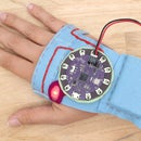
Step 6: Prep Dial Plates


There are two settings, one chooses the kind of meat, the other chooses the level of doneness. Download the dial design jpeg at it's original size or print from Illustrator. You can use plain white copy paper, or something a little heavier if you wish. Attached are also the .ai files so you can alter them to include the kinds of food you love to grill.
Laser Cut Acrylic
To protect the paper prints and add to the retro feel, laser cut two rings from the 1/8" clear acrylic.

Step 7: Mark Control Box


Gather all the components and arrange them on top of a piece of paper where you have drawn out the dimensions of your enclosure. Lay them out until they look good, making sure there is enough room left around the rotary switches for the acrylic plates. Measure and take note of the diameter of each component.
Use the ruler and pencil to mark the middle of each drill hole on the top face of the box.
As mentioned before, my box is built for four temp probes and four rotary switches. The Edison, as-is, can only support two of each, so disregard the extra components pictured.
Step 8: Drill Holes in Control Box

To help with drilling, take a sharp object and make a divot where the center marks are. Alternatively you can drill a smaller hole first, then drill the final.
If you happen to have stepper drill bits, use those! I discovered these during this project, they are heaven sent. They do not getting caught on the material as it goes through, producing a smoother hole in the end.
Dremel Opening for LCD
Using a Dremel, the rectangular opening for the LCD display can be created. There are different ways of achieving this, the Dremel bits used to create the opening for this project were:
- cutting wheel
- Drywall cutting bit
Clamp down the enclosure and fit the Dremel with a drill bit. Use the cutting wheel to make the first cut along the length of the marked opening. Make sure to allow for the width of the wheel. It won't be able to get the corners very well without cutting past them, be careful not to go too far. After cutting the edges out as much as you can without going past the corners, attach the drywall bit, go in and start cutting out the rest and cleaning up.
Notes on Finishing
The result won't be super smooth and the corners will end up rounded. To clean up the edge after installing the screen create a frame with acrylic or use sticky back tape or foam to go around the edges to hide them.
Step 9: Paint Control Box (optional)


Go to a well ventilated place and put down some plastic or paper to cover the area you are going to paint on. Give the box two light coats with a plastic primer, then a heavier coat for it's third. Be careful not to linger too long in one spot or you will produce paint drips. Let the primer dry for about 30 minutes.
Do the same three coats with the final color and let dry completely.
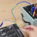
Step 10: Calibrate Thermistors


Thermistors change in resistance when exposed to hot and cold temperatures. The change that occurs does not happen in a linear fashion however, so when temperature is mapped to the thermistor's resistance on a chart the line produced is a curve.
Fortunately there are smart people out there who have given us tools that can be used to translate the resistance to the correct temperature. I used a calibration sketch copyrighted by Tony DiCola and released under the the MIT license. The sketch takes the 3 temperature inputs and finds the three coefficients needed to plug into the Steinhart-Hart equation. This equation will translate the resistance of the thermistor to temperature in fahrenheit.
- Take a thermistor and a 10K resistor and connect it to an analog pin using a voltage divider circuit.
- Fill 3 glasses with water that vary in temperature: ice, room temperature and hot. You will also need the digital thermometer to read the temperature of each glass of water.
- Upload the code to the Edison with Arduino breakout. Open up the serial monitor and follow the instructions. Once you have completed the instructions, you will get three coefficients, write these down, they are plugged into the final code.
Attachments
Step 11: Cut Off LCD Connector

Used in this project is the Grove RGB backlit LCD screen, it uses I2C as the communication method with the Edison. On the Arduino breakout, you can connect to the I2C bus through A4 and A5. The Grove Base shield can be used on top of the Arduino breakout, which the sensor plugs into, but it takes up too much real estate vertically. So, instead of using the shield you can bypass it by clipping off the connector.
Red -- +5V
Black -- GND
White -- SDA/A4
Yellow -- SCL/A5
Step 12: Build Circuit

Download and print out the attached schematic for easy reference. I recommend using the Adafruit proto shield to build the circuit on, this way the circuit can be removed from the breakout board at anytime.
The 8 position rotary switch is the meat selector, the 6 position rotary switch is the temperature selector (rare, med-rare, etc.) The meat selector is read on Analog pin 0 by creating a resistor ladder with 1K resistors.
Once you select the kind of meat and level of doneness, you push the shout-out button on pin to tweet to the world. Announcing that the grill is getting fired up and to bring over a alcohol pairing. You can change parts in the code so it tweets anything you want. The second button turns on the LCD screen and sends out a tweet once the desired temperature is reached. Install a third rocker switch in series with the power line that can turn on the whole circuit.
Before soldering anything, position the Edison on the bottom of the project enclosure and measure how much wire you need to for each component to reach to it's opening.
Power
Plug the external power either through using the barrel jack or VIN. A 9V battery fits nicely in the enclosure box and should last a good amount of time. You can read more about how to power the Arduino dev board and all that it can do by downloading the attached hardware guide.
Attachments

Step 13: Set Up Twitter Account


The first step to enabling an inanimate object to tweet, is to give it a name. A trip to the flea market ended up gifting me the name of my grill in the form of a vintage belt buckle.
The second thing is to set up a Twitter account. This is when you pick out the display name and Twitter handle and you start to follow your friends. Make sure to tell them to follow the grill so they can get updates on your social gatherings!
Step 14: Set Up Twitter Library

Sending tweets is done easily using the Arduino library written by NeoCat. Go to the website and follow the 3 steps on the homepage.
You will be asked to get an access token that will get you through Twitters authentication protocol that is setup for developers. Download the library from the provided link and put the library folder in the correct directory, ~/Documents/Arduino/libraries (Mac) or My Documents\Arduino\libraries\ (Windows). Create a folder named "libraries" if it does not exist already.
Open Arduino and navigate to the demo sketch. Plug in the access token and send your first tweet!
Step 15: Connect to WiFi

In order for the tweet to be sent out to the twittersphere, your microcontroller will need to be connected to a network. For the Edison, make sure to set up and enable your WiFi abilities. If you haven't set up WiFi yet, follow the instructions on Intel's website. Choose your OS, then scroll down and click "connect your board to the internet" and follow the instructions. One cool thing about the Edison is that once you set up WiFi by running the command "configure_edison --setup", it automatically connects to the network upon boot up.
I've connected and setup boards using Windows and OS X without any problems. Let me know in the comments or in a message if you have any problems.
Step 16: Upload Code

Once you have sent your first test tweet, it's time to upload and finalize the code. Download the attached file and open it in the Arduino IDE, make sure it's the Intel version if you are using an Edison. If you wish, you can first make sure your all your switches and knobs are working by printing the values to the serial monitor. Here you can also check the ranges of the the resistor ladder you created that is your meat selector to see if the ranges in the code match up. Don't forget to change any pin assignments if components are moved around.
There are a few places that you will need to plug info in the code. Grab the three coefficients that you wrote down from the calibration sketch and put them here, you will find this block at near the top.
////define coefficients taken from calibrating sketch
#define     A_COEFFICIENT         -0.00012185168
#define     B_COEFFICIENT         0.000283187503
#define     C_COEFFICIENT         0.000000003224
The last thing is the access token that was generated through using NeoCat's twitter library website. Put that in the tweet function found near the bottom of the sketch.
//// tweet function/////
void tweetMessage(String stringMsg) {
  // PLUG IN YOUR ACCESS TOKEN BETWEEN THE QUOTES
  Twitter twitter("PUT YOUR ACCESS TOKEN HERE");
  //Convert message to a character array
  char msg[140];
  stringMsg.toCharArray(msg, 140);

  if (twitter.post(msg)) {
    int status = twitter.wait();
    if (status == 200) {
      Serial.println("OK.");
    }
    else {
      Serial.print("failed : code ");
      Serial.println(status);
    }
  }
  else {
    Serial.println("connection failed.");
  }
}
Attachments
Step 17: Install Circuit and Mount Components


Mount Components
Unscrew all the nuts from the switches, pots and LEDs and set aside.
From the inside of the enclosure, push the components through their respective openings. Take the nuts and screw them on top of the components to secure them in place. Put some 5 minute epoxy around where the component and box meet for more holding power. This especially helps when you are using a plastic box, like I did. If it's not wood, the rotary switches don't grab as well since there isn't anything for them to sink their teeth into.
Use the epoxy for anything else, my sub-mini jacks were for PCB mounting, so I used epoxy around the casing and glued them in place behind the openings, from the inside. Secure glued items in place with duct tape as they set.
Install Circuit
Use some sticky foam to attach the Edison board and battery to the bottom of the project enclosure. Once they are good and stable, screw the bottom on.
Step 18: Control Box Meets Nadine

Originally the control was going to be mounted on the side shelf, but I actually decided to leave it free. This gave me freedom to move it around as needed.
If I wanted to mount it, I would use one of the bolts that hold the wood slats to the metal brackets. Assuming that you want to mount it and that you have a similar setup, drill a hole at the bottom of the enclosure and line it up with the other two holes. Pop the bolt through the enclosure, down through the wood and metal and screw the nut back on.
Step 19: Turn on and Enjoy!

It's complete!
It's very useful as a way to monitor the temperature. The social aspect adds fun and interactivity to the event, as well as a good reminder for people who are planning to come. It also let's them know what alcohol goes best with the food that's on the grill. Keep in mind, you can program it to tweet whatever you want, so don't feel limited by what I suggest here.
If you are a serious griller, a good next step would be to pipe this information into Intel's IoT cloud-based analytics. This way you can map temperature against time and see how your grill performs under different conditions.
But, don't wait! Go grab some meat, fish and veggies, fire up the grill and let the guests take care of the drinks.


