

Introduction: Neon Ring Counter Heart


Valentine's Day is always accompanied by a fierce swirling of emotions. I find myself light-headed, out of breath, and anxious counting down the days to February 14th. This time of year, I ask myself some of life's hard questions, questions like: "When will my parts arrive? What happened to my wire cutters? Who melted my soldering iron? Why is my table on fire?" Yes, because for many makers Valentine's Day is an annual, obligatory challenge to make a gift for someone. Although you'll definitely be more attached to your creation than they'll be, it's the thought that counts!
This flashing heart is unique for two reasons:
- It uses neon glow lamps instead of LEDs.
- It lights the bulbs sequentially without using any sort of digital circuitry. (Only the neon bulbs, resistors, capacitors, diodes, and 90V DC!)
I'm a big fan of neon bulbs, so I was excited to discover that they can do some things modern LEDs flat-out can't. This circuit is called a neon ring counter, and it uses the switching properties of neon bulbs to light one bulb at a time in a loop with any number of bulbs. I modified the circuit slightly so I could use a neon bulb to generate the pulses that make the ring counter advance. (The center bulb flashes each time a new outer bulb lights, but because the flash is so brief the camera doesn't always catch it.) Inside the case there's an adjustable 5V to 90V converter powered by USB to drive the ring counter, so you can power the heart from a phone charger or probably a laptop.
One unusual part of this project is that you'll need to customize the circuit for every heart you make. The NE-2 neon glow lamps I chose don't have very precise striking and maintaining voltages, so to make a reliable ring counter it's necessary to age a batch of bulbs with AC and then select bulbs with similar electrical characteristics, as explained below. The resistors and input voltage for the ring counter depend on the striking and maintaining voltages of your bulbs, so I can't give you one-size-fits-all values, but I'll show you how to calculate them.
This project requires through-hole and SMD soldering, ordering two custom printed circuit boards, and 3D printing a case. In addition, it's necessary to breadboard and test the neon ring counter with your aged bulbs, since this circuit can take some tweaking to make it work well with common neon indicator lamps. The only danger with this project is aging the neon glow lamps, which involves connecting them through a resistor to the high-voltage AC wall power. Mains voltage is dangerous, and you should only attempt this project if you understand and acknowledge the risks.
Let's get to it!
Supplies
Tools:
- Soldering iron and solder
- SMD soldering equipment (solderpaste, hot plate or reflow oven, tweezers)
- 3D printer (I used a resin printer, an FDM printer could work though)
- Breadboard for prototyping
- Multimeter
- Wire cutters and wire strippers
- Glue (I used tacky glue, which is convenient because it turns clear when it dries)
Parts:
This project requires surface-mount resistors and capacitors. There are variety packs available online (like this one), which I would recommend if you want to get into surface-mount soldering.
Ring Counter Heart:
- Custom PCB
- NE-2 Neon Glow Lamps (like these)
- 17x assorted 0805 resistors (you'll need to pick resistances to match your bulbs, as described below)
- 7x 100nF 0805 capacitors
- 1x 0.1uF 100V ceramic capacitor (here, lower capacitance could work but needs to handle 100V)
- 1x 0.47uF 100V ceramic capacitor (here)
- 7x 1N4148 through-hole diodes
- Braided wire (to connect the heart to the power supply)
5V to 90V Adjustable USB Power Supply:
- Custom PCB
- 1x 10M 1206 resistor
- 1x 220 0805 resistor
- 1x 22k 0805 resistor
- 3x 0.1uF 100V ceramic capacitors (same as for the ring counter)
- 3x MUR120 switching diodes 200V (here)
- 1x 150uH 1A fixed inductor (needs to handle up to 1A without saturating)
- 1x LT1073 DC/DC converter chip (here)
- 1x USB type A receptacle, right-angle (here)
- 1x 10k RM-065 trim pot (like these)
- 1x 2-pin screw terminal (like these)
- 1x USB A male-to-male cable (like this, they're nonstandard so double check that you have one. If I did this project again I would use USB mini or micro!)
Case:
- 4x 4mm by 5mm M3 screw inserts (like the ones here)
- 4x 12mm M3 screws (like the ones in this variety pack)
Step 1: Neon Ring Counter Circuit


(This is based on Ronald Dekker's excellent site on neon ring counters. If you want more information on neon glow lamps in general, check out my previous Instructable or this excellent overview.)
Neon ring counters take advantage of the fact that neon lamps turn on or "strike" at one voltage, and then the voltage across the bulb immediately drops to a lower "maintaining" voltage, below which the bulb will turn off. The key to the ring counter is that if a neon bulb is given a voltage halfway between its striking and maintaining voltages, it will only take a small negative change in voltage to turn the bulb off, or a small positive change to turn the bulb on. Let's see how it works with some hypothetical neon lamps that have a striking voltage of 80V and a maintaining voltage of 60V.
1. Initially, the bulb on the left is on and current flows from the 90V power supply, through the left bulb and a diode and resistor to ground. Since the bulb is on, the voltage across it is 60V, so the capacitor in the middle charges up to 70 - 60 = 10V.
2. An external pulse generator delivers a -20V pulse capacitively coupled to the shared wire of the bulbs, which causes the voltage given to the bulbs to drop from 70V to 50V (watch the black arrow in the upper left). This is less than the left bulb's maintaining voltage, so it turns off. The capacitor in the middle is still charged up to 10V, and it can't discharge because of the diode on the right, so the bottom of the right bulb takes on a voltage of -10V.
3. The voltage of the shared wire rises back up to 70V. This isn't enough to cause the first lamp to strike, since 70V < 80V. However, the second lamp had -10V on its bottom side, and 70V - (-10V) = 80V. Since the charged capacitor lowered the voltage on the negative side of the second bulb, the voltage across the second bulb reaches its striking voltage, so the second bulb turns on. Current flows through the second bulb and its resistor and diode to ground, and the capacitor in the middle charges up to 10V in the opposite direction it was charged previously.
To make a ring counter with multiple neon lamps, all you have to do is add another lamp, diode and resistor in series, then connect a capacitor from the negative side of the diode in the previous stage to the positive side of the diode in the new stage. Then, if you connect the final stage to your first stage, you'll form a loop and the neon glow lamps will go around in a ring forever and ever and ever - that's why it's called a ring counter!
When we design our ring counter, we'll want to decide on values for the supply resistor and the resistors under each lamp (the lamp resistors will all be the same resistance). Our goal is to pick resistors that make the current through our neon lamps close to the suggested current from the datasheet, but most importantly to make the voltage on the positive side of the bulbs halfway between the striking and maintaining voltage of the bulbs. These resistances depend on four things:
- Ibulb (bulb current)
- Vstrike
- Vmaintain
- Vsupply
I'll give you the equations for the resistances here, but first I want to point out an important detail: This is all under the assumption that all of your neon glow lamps have identical striking voltages and maintaining voltages! In reality, this is not the case, and it's especially true when using cheap neon indicator lights like the NE-2 bulbs I used. Because of this, it's important to age your bulbs (as described in the next section) to make sure their electrical characteristics don't change over time, and then to measure your bulbs and select neon lamps with similar striking and maintaining voltages. Even then, it's not a given that your ring counter will work, so you should breadboard it and let it run for a long time before soldering things together.
Ok, here are the equations. They come directly from the fact that we want the current through the bulbs to be Ibulb and the positive side of the bulbs to have a voltage halfway between Vmaintain and Vsupply. I'm calling the single power supply resistor Ra, and the multiple neon lamp resistors Rc.
- Rc = (Vstrike - Vmaintain) / (2 * Ibulb)
- Ra = (Vsupply - Vmaintain - Ibulb * Rc) / Ibulb
Ronald Dekker derives these equations and extends them to cases when your bulbs don't all have the same striking and maintaining voltages, so check out his site if you're interested - there's a lot of good stuff about ring counters there.
One more thing - we need to generate the pulses that make the ring counter advance. I chose to do this with a simple neon glow lamp relaxation oscillator. A capacitor in parallel to a neon lamp charges up to the striking voltage, causing the lamp to turn on and discharge the capacitor to the lamp maintaining voltage, and so on. The neon lamp voltage forms a sawtooth-like wave instead of a pulse, but I was able to make it work with the ring counter with hardly any trouble (as long as the pulse drops low enough to turn the previous bulb off, the voltage to the bulbs will rise until it forces the next bulb on). If you're making a ring counter for a clock, then I wouldn't recommend this because the frequency of the relaxation oscillator depends on the capacitor, the resistor, and the striking and maintaining voltages of the neon lamp. The neon bulb's voltages can change over time as the lamp ages or even be affected by the ambient light level (this is called the dark effect), and you wouldn't want that to make your clock lose track of time! A neon relaxation oscillator is perfect for us though, since we don't care about the precise frequency changing and the flashing bulb makes it look like the heart is beating.
Now that we understand the neon ring counter circuit, we'll age some neon bulbs and pick ones with similar striking and maintaining voltages, and then breadboard the circuit.
Step 2: Age Your Neon Lamps


WARNING: THIS STEP INVOLVES MAINS POWER, WHICH IS DANGEROUS.
There's a lot of variance in the striking and maintaining voltages of neon bulbs of the same type, and the characteristics of individual bulbs will also change over time. To pick good bulbs for our ring counter, first we have to "age" our neon bulbs by running them for a while with AC at a higher current than normal, which will mostly stop them from changing too much in the future. Then, we have to measure the striking and maintaining voltages of all the bulbs we aged, which will allow us to select a batch of similar bulbs for our ring counter.
I aged my bulbs by connecting them to the 120VAC mains power through a 56kohm resistor (if your wall power is different, pick a different resistor!). The maintaining voltage of my NE-2 bulbs is around 60V, so this will give a peak current of (120V - 60V)/56kohm = about 1mA. This is about double the recommended current for an NE-2 bulb, which is good because we're trying to wear the bulb in. I aged each bulb for 72 hours, and aged a total of 20 bulbs.
After aging, I measured the striking and maintaining voltages of the aged bulbs. Connect a variable DC power supply (such as the one I'll make in step 5) to a neon bulb through a resistor, and measure the supply voltage with a voltmeter. Start with the power supply at about 60V and the neon bulb off. Then, slowly raise the supply voltage until the neon bulb strikes. The supply voltage will now be approximately the neon bulb's striking voltage. Measure the voltage across the bulb to get its maintaining voltage. You can repeat this process a few times for each bulb and average the results to get more accurate numbers, but being off by a volt or two shouldn't make much of a difference for the operation of your ring counter. I wrote a number on the bottom of each of my bulbs with a sharpie (this was pretty hard!) and then recorded their striking and maintaining voltages in a table.
I should emphasize that I measured the striking and maintaining voltages of these bulbs with DC, and only in one direction. Neon glow lamps are not symmetric, so you'll observe a slightly different striking and maintaining voltage if you flip the bulb around - when I did this for one bulb, I found the striking voltage was different by around 2 volts and the maintaining voltage was about the same. Again, this disparity didn't matter when I built my ring counter, but if weird things are happing with yours then this could be one of the causes.
After recording the voltages of all my aged bulbs, I plotted their striking and maintaining voltages and selected groups of bulbs with similar characteristics for my ring counter. The hearts I made have a ring counter with 7 bulbs, and I made two hearts, so I picked two groups of 7 bulbs and breadboarded ring counters using these. Since I generate the pulses to the ring counter with a neon relaxation oscillator, I also chose one bulb for the oscillator for each heart. I suggest picking an oscillator bulb with a striking voltage on the lower end of the bulbs for your ring counter, since I had a little trouble with getting the power supply voltage dialed exactly right for the first heart and that wasn't a problem for the second one where I picked an oscillator neon bulb with a low striking voltage.
Luc Small does a good job explaining how to age neon bulbs for a ring counter, so check out his site if you're interested - his bulbs are different than ours, but the process is the same.
Now that we've gone through the trouble to prepare our neon bulbs, we hopefully won't have any problems making a working ring counter!
Step 3: Prototype the Ring Counter


Now that you've selected some neon bulbs, calculate:
- The average striking voltage, Vstrike.
- The average maintaining voltage, Vmaintain.
We'll use Vstrike and Vmaintain to calculate good values for the supply resistor Ra and the resistors under the neon bulbs Rc - don't just use the values given in my schematic! Here are those equations, which I also mentioned when talking about how a ring counter works.
- Rc = (Vstrike - Vmaintain) / (2 * Ibulb)
- Ra = (Vsupply - Vmaintain - Ibulb * Rc) / Ibulb
We also need to make the neon relaxation oscillator. I used a 0.47uF ceramic capacitor in parallel across the oscillator bulb, and a 0.1uF ceramic capacitor to capacitively couple the pulses to the ring counter. Both these capacitors need to be rated for 100V (but the 0.1uF capacitors between the ring counter stages don't need to be). I think a smaller capacitance than 0.1uF for the coupling capacitor might give you better results, but I used what I had on hand. Start with a big resistor (2Mohm) that connects your relaxation oscillator to the power supply, then after you've happy with the way the ring counter is working, you can use a smaller resistor to speed up the ring counter.
Before you break out your calculator, let me give you a couple tips that might save you some of the pain I went though. The resistors Rc and Ra are critical to making the ring counter work reliably, so I put two resistors in series to form Rc to get an accurate value (I used one resistor for Ra because my supply voltage is adjustable). Even this might not be enough though, so if you can't quite find resistances that satisfy the equations for Rc and Ra, or your ring counter doesn't work, then here are a couple things to try:
- Calculate Rc for the recommended neon bulb current, then pick the nearest resistance you can make (by adding two resistors together) and solve for Ibulb. The current through the neon bulb isn't very critical to the circuit, so it's okay to pick a value for Ibulb that lets you make Rc exactly with the resistors you have on hand. Use this new value of Ibulb in your calculation of Ra.
- If you have an adjustable power supply, then you can pick a supply voltage such that Ra ends up on a convenient value. Make sure your supply voltage is greater than the striking voltage of the bulbs. I would stay between 80V and 90V. Also keep in mind that changing the supply voltage will change the rate of the relaxation oscillator.
- Start small. Build a ring counter with two bulbs. Then add a third, a fourth, and so on. You might find that adding one particular bulb causes the ring counter to break, or that the circuit doesn't function when the bulbs are in a certain order. This is the reality of making a ring counter with neon indicator lamps that are only designed to be lights. If bigger ring counters really aren't working out, then you can always age more neon bulbs and select bulbs with more similar striking and maintaining voltages.
Keep in mind that the neon ring counter doesn't have to be completely perfect; we're making a flashing heart, not a clock, so it's okay if the ring counter skips once every hundred pulses or doesn't tick at a constant rate. I've noticed that my ring counters flash faster during the day than at night. This makes sense, because when there isn't enough ambient light the striking voltage of neon bulbs is higher (this is called the dark effect), and that would decrease the frequency of the relaxation oscillator. If that's the only problem with your ring counter, then I would say that you've succeeded, and now we can move on to making a cute enclosure for the ring counter.
Step 4: Design the Heart-Shaped PCB


I decided to use Autodesk EAGLE to put the ring counter on a heart-shaped PCB, with the ring counter neon bulbs along the outside and the oscillator neon bulb in the middle. This gives the impression that the heart is beating since the middle bulb flashes each time the ring counter advances, which I thought was pretty neat. I used 0805 surface-mount resistors, and 0805 surface-mount capacitors to link the ring counter stages together, but kept the oscillator capacitor and the coupling capacitor as through-hole since they need to be rated for 100V. I picked 1N4148 diodes, but I think other diodes would work just fine. The vias at the top of the PCB are for the the ground and 90V wires from the adjustable DC supply. The wires will be soldered in from behind the board, so we won't actually see those wires when the case is fully assembled.
One important thing to keep in mind if you decide to make this yourself: make sure to change the name on the upper left of the board. I don't think your special someone would be too happy if you got them a heart with someone else's name on it!

Step 5: Supply a Supply! (60-100V DC From 5V USB)


We need a convenient way to supply 90V or so DC at low current to the ring counter, so I also designed a PCB that converts 5V from a USB jack to any voltage between 60V and about 100V. This uses the LT1073 DC/DC converter and a voltage multiplier in exactly the same way as my last Instructable, a wirelessly rechargeable Neon Lamp Tea Light. I explain the operation of the LT1073 in detail there, so I won't go into it much here. The 10k potentiometer R1 determines the output voltage, so turning the potentiometer left all the way will give around 60V, and turning the potentiometer right will give a maximum of 100V. One more thing to know is that the 220 ohm resistor R2 will limit the current draw of the LT1073 to less than 500mA. This means that, theoretically, a computer should consider this circuit a high-power USB device and happily deliver 5V at 500mA or less. This seemed to work when I tried it, but I care about my computer quite a lot, so out of fear and cowardice I now have my heart plugged in to an old phone charger.
I have to admit, I made an awkward mistake when designing this circuit. The USB connector here is a standard USB type A female connector. This means that you need a cable with a USB type A male connector on each end if you want to plug this power supply into a computer or a power brick. Well, apparently, that's not allowed! Wikipedia actually labels such a cable as "Proprietary, Hazardous." Supposedly I should have used a USB mini or micro connector on my board, which I probably would have done in the first place if I didn't already have these USB type A receptacles lying around. This isn't a real problem since you can still buy these "hazardous" cables online, but it's something to keep in mind.
I also decided not to put a switch on the case for the heart, since I thought it would look a little ugly and wasn't necessary. I figured I would reuse this supply for other projects though, so I included space for a small "on" switch on the bottom left of the board, although we'll just be soldering those two vias together with a wire.
Step 6: Order Your PCBs

I ordered my printed circuit boards from PCBWay. It only cost about $5 for 10 boards per design (not counting shipping), and my boards arrived in a week. I also ordered a solderpaste stencil for the heart, which makes soldering all those tiny resistors and capacitors a lot easier. I'm really happy with how the red soldermask turned out on the heart, it looks very Valentines-ey!
When your boards arrive, make sure that all your components fit nicely into the vias on the board, the SMD pads are the right sizes, the wires fit through the 90V and GND vias, and so on. It's also important to do a continuity test. It's especially important to check that 90V and GND aren't connected, since that would be a good way to fry the LT1073 in the 90V supply.
If everything checks out, then it's time to solder!
Step 7: Solder the Heart and the Supply


As you can tell from this gif, I am definitely a master of surface-mount soldering!
I won't give a tutorial on surface-mount soldering here, but there are plenty of tutorials online, and I talk about it some in Step 8 of my previous Instructable. Basically, squirt a little solderpaste on all the copper pads, carefully place your components on their pads using tweezers, then heat up the board until the solderpaste melts and connects everything. Solder the SMD components before the through-hole components since you won't be able to heat up the board on a hotplate if the leads from through-hole components are sticking through.
I do have some advice regarding the neon bulbs. First, when you solder the neon bulbs make sure the positive lead of the bulb on your breadboarded ring counter goes into the positive via for the bulb on the PCB. This is the via closest to the edge of the board, connected to the big heart-shaped trace on the bottom. I mentioned earlier that neon bulbs are asymmetric, and that the DC striking and maintaining voltages in each direction are slightly different. I also said that this probably didn't matter, but your ring counter was working perfectly fine in the breadboard; there's no reason for us to throw a wrench in things by reversing the neon bulbs. It's also important to put the bulbs in the PCB in the same order. The bulbs will light counterclockwise, so make sure this matches with the order of the bulbs in your ring counter.
Secondly, when you go to solder a neon bulb, only solder one lead in at first. Do this for all the bulbs, including the oscillator bulb in the middle. Then, once all the bulbs are on the board, you can bend the bulbs a little to make sure they're straight and all facing the right direction.
Finally, remember to solder the 90V and GND wires (which should be braided-core wires for flexibility) into the board from behind. This is the opposite of all the other things we've soldered in, but by soldering the wires in to the back we can hide them inside the case.
Once you're done soldering, connect the ring counter's wires to the power supply's screw terminals and plug it in! Make sure to adjust the voltage of the supply to match the Vsupply you decided on when designing the ring counter circuit. If your heart starts beating, then we can move on to designing a neat case!
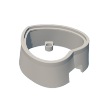
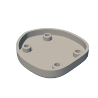
Step 8: Design a Case


I designed my 3D printed case in Fusion 360, and I think it turned out pretty well! Eagle created 3D models of both of my boards and sent them over to Fusion, which made it pretty easy to put things together (although a couple colors got messed up, not sure about that).
The case will print in two pieces, a base piece and a walls/top piece. The heart PCB sits in an indentation in the upper part of the case, while the power supply sits on the bottom part. There are holes to hold screw inserts in the top piece, and holes for flat-headed screws to go through on the bottom, so the case screws together with four screws. The screws go through those drill holes in the corners of the power supply PCB, holding it in place, which is important because it takes moderate force to plug in a USB cable to the power supply. The flat-head screws sit flush with the bottom of the case (hopefully).
I couldn't think of a tricky way to secure the heart PCB without covering part of it, so we'll just glue that in. I suggest using some sort of transparent glue - I used tacky glue.
Our case looks pretty sweet, so let's try to print it!
Step 9: Print & Test the Case, Glue the Screw Inserts


I printed the attached STL files using a resin printer (a QIDI TECH Shadow 5.5S), but you can probably print this with any printer. You might want to consider adding some support structure if you use an FDM printer.
If you successfully printed the case, congrats! Stick an extra heart PCB in the top of the case to make sure that it fits, and then do the same with the power supply PCB in the bottom of the case. Check that your 12mm M3 screws fit nicely in the bottom holes and poke up through the drill holes of the power supply. If the fit of the screws looks good, then the next step is to secure the 4mm x 5mm M3 screw inserts in their holes in the top part of the case.
Because I used a resin printer, it was convenient for me to spread some photosensitive resin in the holes on the top part of the case, squeeze the screw inserts in, and cure it with UV light. If done right, this will fill all the extra space in the hole and hold the screw insert in very effectively. If you printed the case using an FDM printer, I imagine you could use some sort of superglue to hold the screw inserts in place.
Once your screw inserts are in, try screwing the case together! Don't screw it too tightly, since it shouldn't take too much force for the screws to hold the case together, and you could twist out the screw inserts if you crank on them too hard. If the case fits together nicely, then it's time to glue the heart in.
Step 10: Glue the Heart PCB

Before you glue the heart PCB into the case, it's important to make sure the wires are a good length. If the wires are too long, it'll be hard to assemble the case and fit all the extra wire in. If the wires are too short, well, then they won't reach the power supply! Press and hold the heart in the top of the case, and bring your power supply up against the bottom of the screw insert holders that it would rest against. Now check that the wires reach the screw terminals of the power supply. If they do, then try to gauge how much extra wire there is, cut it off, and strip the wires again. Don't cut it too short! If you do, you'll have to desolder the wires and solder new ones back in. (This happened to me...)
Once the wires are a good length, we can glue the heart in. I used tacky glue since it's not completely permanent and it turns clear when it dries. Put the heart in its place and bend the wires so they go out the slot for the USB - this will stop the wires from pushing the PCB out when it's trying to dry. Then put some tacky glue on a toothpick and spread it evenly around the inner rim of the case, the part the PCB will directly touch. After you have a thin layer of glue, squish the heart into place and press firmly for a little while. Once it seems like the heart won't fall out, clean the excess glue off the inside and outside of the case. Avoid getting any glue on any wires, since tacky glue is water-based and our high-voltage, low-current signals will be affected by even a little leakage through the tacky glue. It's okay if you can still see white spots, like in the picture; the glue will turn transparent once it's dry.
Let the glue dry for at least two hours, preferably longer. After that, the glue should have turned clear, and your heart will be stuck in place!
Step 11: Put It All Together!
We're almost there! Hold the top part of the case (with the heart now glued in) upside down in your hand, so you have easy access to the 90V and GND wires for the ring counter. Screw these wires into the screw terminals on the power supply, and hold the power supply in place against the screw insert holders with the USB connector poking out the slot on the side. You might have to bend the wires a little to stop them from pushing the power supply out.
Put on the bottom of the bottom case, and screw it in. Make sure the screws go through the drill holes in the power supply PCB, and don't screw them too hard. Hopefully the screws will sit flush with the bottom of the case.
Once the heart is assembled, try plugging it in! The case is pretty light compared to the USB cable, so make sure to tape the cable down or something so your heart doesn't fall off the table.
Step 12: Results


Congratulations, you've completed your adorable neon ring counter heart! How did it turn out? I'm really happy with how this project went, I thought it would be hard to make a ring counter using NE-2 bulbs from what I heard online but it wasn't too bad. I like the aesthetic effect of the light traveling around the outside when the middle bulb flashes, especially with the red PCB.
I got so attached to the first heart I made (the black one) that I couldn't bear to give it away, so I made a second one as a gift. They count at slightly different rates, but I also think that's pretty cute.
This neon ring counter circuit only scratches the surface of what you can do with neon glow lamps. I'll refer you to this article about ring counters and this overview of neon glow lamps. Supposedly, it's even possible to make logic circuits using neon bulbs... I'll keep posting my neon bulb projects here, so stay tuned!

Participated in the
Make it Glow Contest


