

Introduction: Program Arduino Mini 05 With FTDI Basic


When you need a small arduino with an good amount of I/O pins, the Arduino Mini is for you. This is one of my favorite microcontrollers for wearable tech projects because of its size.
Step 1: Materials


Male headers
Jumper cables or solid hook-up wire
Breadboard
LED
Soldering Iron
Solder
Step 2: Prep Arduino
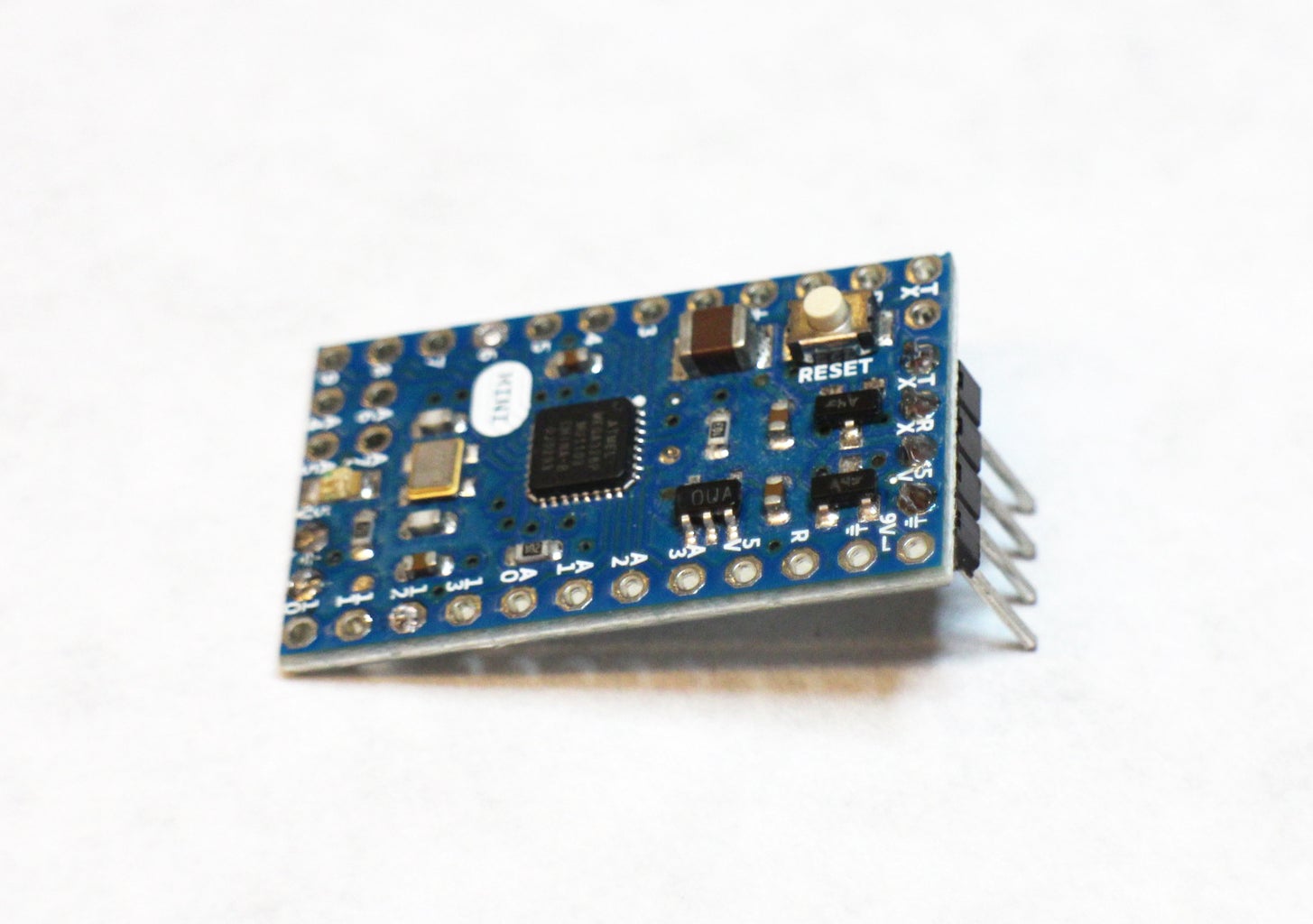


You only need to connect to four pins of the Mini in order to program it. To make it breadboard friendly solder 4 male headers to the TX, RX, 5V and ground pin. The ground pin is annotated with the schematic symbol. It looks like a little tree.
Step 3: Connect


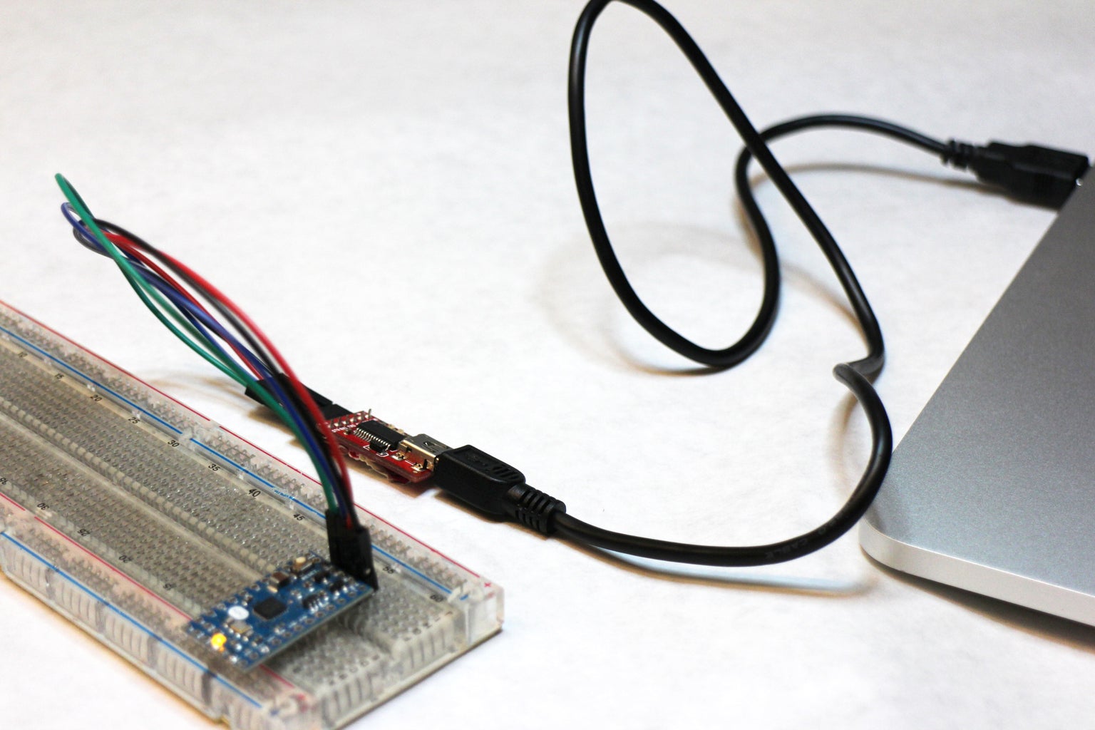
The connections to make from the FTDI board and the Mini are:
GND >> GND
5V >> 5V
RX >> TX
TX >> RX
After the connections are made, take the USB cord, plug into the FTDI, then to a free port on your computer.
Step 4: Upload Sketch


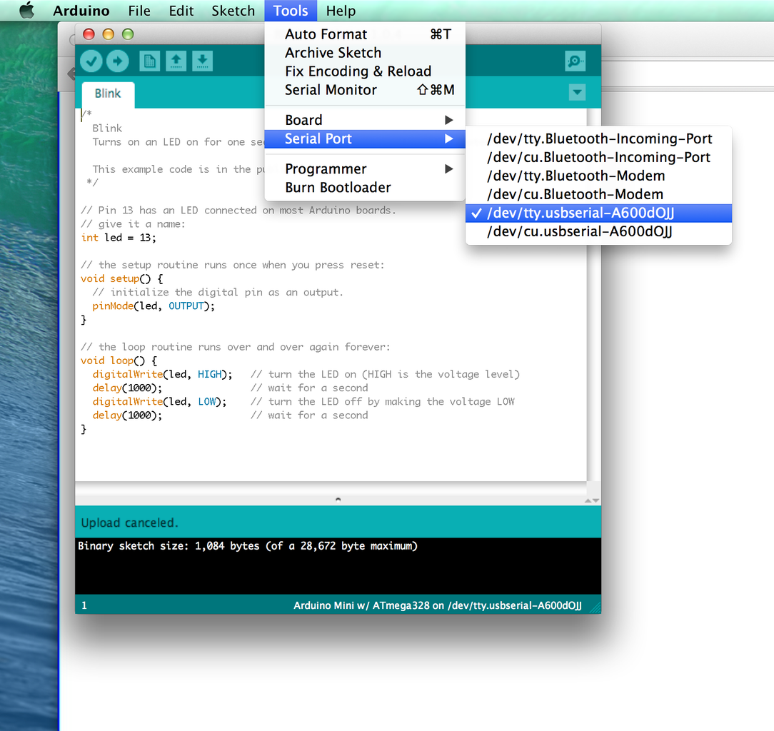

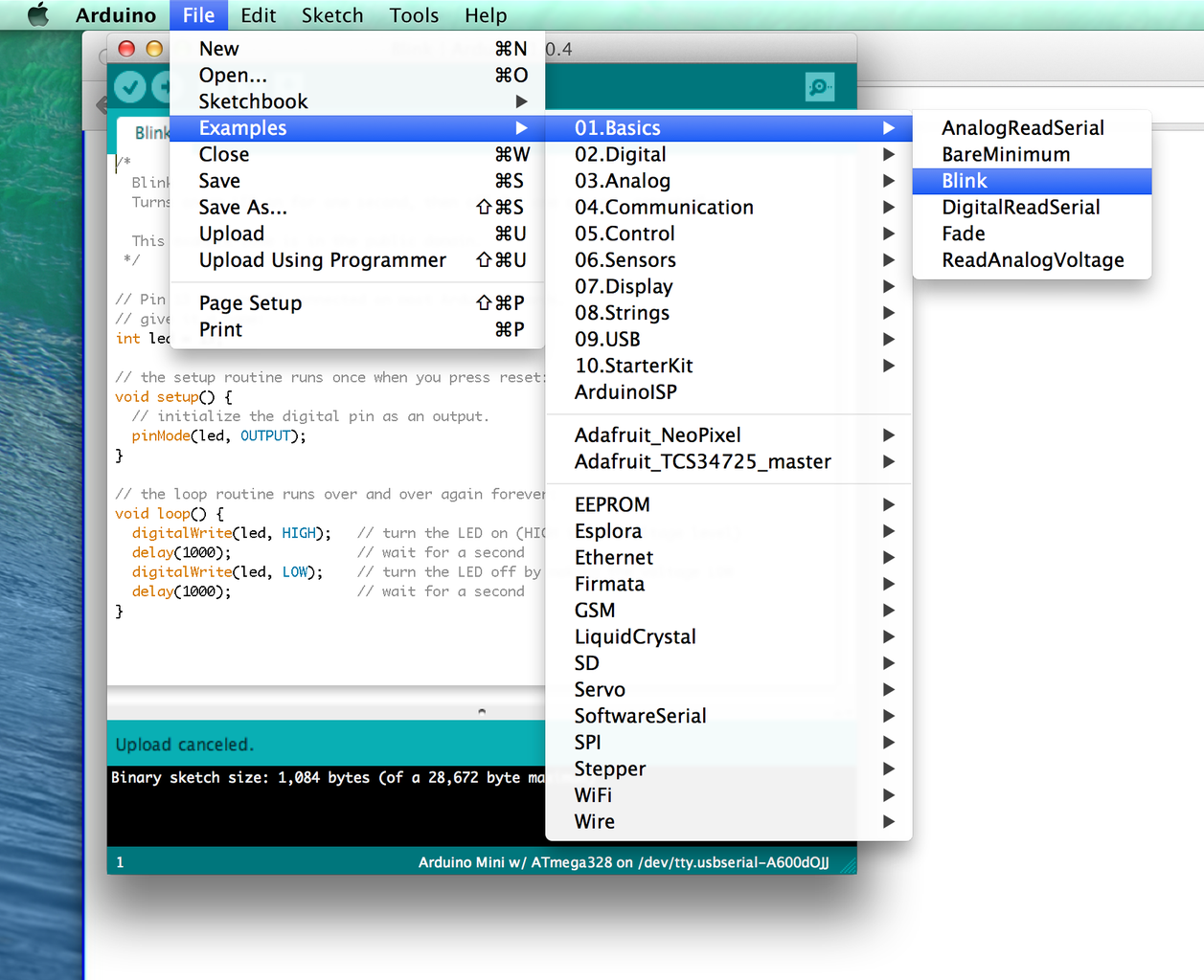
Open the Arduino environment, go to:
File > Examples > Basics > Blink
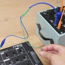
Ok, so here's the trick, once you press the upload button it will say "Compiling sketch..." at the bottom of the sketch window. As it says this and right after you press upload, press the reset button on the Mini.
A quick way to check if the program is loading is to glance over to those glorious TX and RX lights on the FTDI, they will be flashing very fast if all is well. Meaning that the board and your computer are talking to each other.
Pick up the LED, connect the positive side to pin 13 (default in example sketch) and the ground to a ground pin. If it blinks, that means success!
If it doesn't, try the timing of hitting reset and check all of your connections.


![Tim's Mechanical Spider Leg [LU9685-20CU]](https://content.instructables.com/FFB/5R4I/LVKZ6G6R/FFB5R4ILVKZ6G6R.png?auto=webp&crop=1.2%3A1&frame=1&width=306)


