

Introduction: Pybot: Python + 3D Printed Robotic Arm
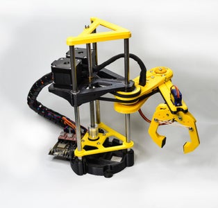


This 3D printed Pybot SCARA Robotic arm has been created using common and affordable elements from the 3D printed World (NEMA 17 motors, Linear bearings, timing belts...)
The idea was to create a reliable, fast, modifiable and accurate Robotic Arm for everyone who wants to have a very cool desktop robot and/or anyone willing to learn robotics and mechanics. The control APP has been created with Python
![]()
Robotic Arm 3D interactive model
We have written a detailed assembly guide, explained the Mechanical design and code on its landing webpage : https://www.jjrobots.com/scara-robotic-arm-by-jjrobots/
The control code has been written in PYTHON, and it has been thoroughly explained and commented for easy understanding.
The control APP for MacOS and Windows is freely available and 100% OPEN. User guide here
All the links to code, assembly guides...etc can be found here: https://www.jjrobots.com/scara-robotic-arm-by-jjrobots/
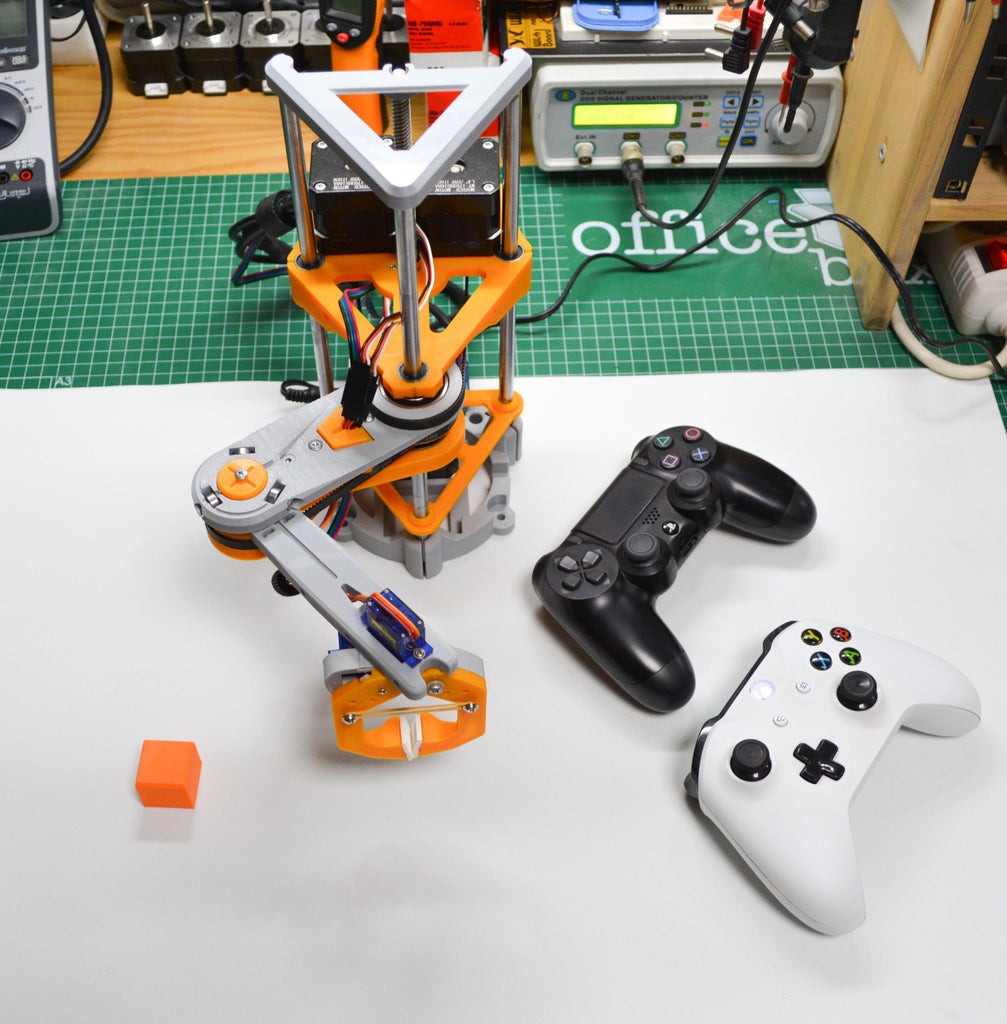
Video: Two SCARAs collaborating picking up and piling up 3D printed cubes. We are using a LEAP motion sensor to control both arms at the same time.

The Pybot´s clamp doing clamps things
Pybot Robotic Arm features:
- Google Blockly controllable
- Trajectory movement (you can add up to 20.000 trajectory points)
- Real Time control using your mouse or Xbox/PS4 controller
- Leap Motion gesture control
- Artificial vision control OPENCV (Use your webcam to tell the robot what to do)
- 100% OPEN SOURCE (Arduino control board and Python control code)
- Control it via USB or WIFI
- Smartphone/ Tablet control APP (for iOS and Android devices)
This pyBot (SCARA type) Robotic Arm has been designed with seven conditioning factors in mind:
- Making it "printable" with any 3D printer in the market no matter its capabilities or limitations
- Use common elements of the MAKER / 3D printer World
- Easy to set-up, OPEN and well documented.
- Python code controlled
- USB+Wifi controllable
- Fun, versatile and easy to modify
 Side and Top view of the pybot SCARA Robotic arm.
This robot mounts three NEMA17 stepper motors and 2 servos (SG90/MG90 or SG92R)
Mechanical specifications:
- Robot frame total height: 270 mm.
- Nº of axis: 3 (arm) + 2 (clamp)
- Working height with the clamp mounted: 145 mm
- Arm (extended) length: 24 cms
- Working area: 1190 cm2
- Horizontal max. speed: 22 mm/s
- Vertical max speed: 25 mm/s
- Total Weight: 2120 grams
- Repeatability (mm): 0.4mm
- Maximum Payload Capacity (arm extended) = approx. 150 g
- Range of motion per axis: Arm: ~190° Forearm: ~280°
- Driving motors: 3x NEMA17 1.8° stepper motor
- Gripper / Actuator drivers: 2x SG90 /MG90 / MG92R servos
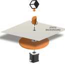
The pyBot SCARA type robotic arm sweeps and angle of approx 315°quickly reaching any point inside that extent. This is an advantage over other robotic arms with vertical elbow configuration (Delta and Polar types) as just one or two simple motor action/s is required to move the arm. Once retracted, the robot is compact and its volume minimal

SCARA arms are good for vertical assembly operations, such as inserting pins in holes without binding or pick and place objects to a certain location when you need speed and accuracy once reached the target. The joints are load points that need robust bearings and high-torque motors or reductions to handle the loads when the arm extends.
They are suitable for complex movements that simulate a human arm with its elbow — reaching under something to grab a part and place it on a conveyor, for example.
 Arm´s covered angle. Due to the mechanical relationships between arm and forearm, a proper control of the forearm is a must during the arm movement.
  The forearm can cover up to 280°. While moving the forearm, the arm´s motor has to be steady (holding itself in position)
  A regular servo (SG90, MG90 or SG92R) will work as wrist and will be mechanically limited to a (approx) 160° angle. The control software has the capability to keep it straight during the movements (to a certain point, limited by the physical construction of the servo)
The main frame: Created using 3 x8 mm stainless steel round bars that will work are rails. A perfect alignment of the 3 bars is mandatory. To help the base´s bars channels to keep the rails straight, a support triangle placed 2 cm over the base with hold the rails firmly. That piece and the top triangle (light grey) will prevent the frame to vibrate when the Z-platform is moving fast up and down.
Moving UP and DOWN
There is a stepper motor embedded in the robot´s base. That motor, rotating, will lift or low the Z-platform. The arm is fitted to this platform so if we lift the platform, we are lifting the arm too.
The motor´s shaft in connected to a threaded rod (2mm/rev) mounting a coupler. This element will do the job of continuing the physical connection between motor and rod and reducing vibrations during any vertical movement. But, how the threaded rod push or pull the Z-platform? There is a threaded nut fitted tight in the platform, so every complete turn of the threaded rod, the nut, will push the platform up, 2mm if rotates clockwise and down if rotates anti-clockwise.
 Side view of the frame with the Z-platform already placed and the Z-motor embedded. All the elements displayed have a role when the robot moves up/ down the Z-platform. The nut (red arrow) does the real job of moving the Z-platform up and down.
The Robotic arm has been designed placing the motor1 and 2 (you will know more about them if you keep reading this document) opposing the weight of the arm and any object lifted by the robot´s gripper. Looking for a good general balance so the linear bearings embedded in the Z-platform does not suffer from any angular force. This will allow to considerably reduce the friction letting the Z axis to be agile and fast.
Moving the arm and forearm
 TOP VIEW of the Z-platform. The motor1 making use of a pulley reduction (16 to 72)
The ARM element will be moved by a NEMA17 motor (motor1) transferring the shaft´s rotation to the component using a gear reduction of 16 to 72. The motor´s shaft has a 16 teeth pulley, which transmits the movement to a 72 teeth gear located on the Robot´s arm. Doing this, we are reducing the rotational speed 4,5 times + increasing the power delivered 4,5 times: We have to rotate the motor1 10° to get a 45° arm rotation
 Simplified representation of the motor1 (green) -driving element- and the arm (red) -driven element-. This gear-belt reduction allows to increase the arm´s power and, at the same time, the accuracy of the arm
 TOP VIEW; Transferring the movement to the forearm from the motor2 using a 16 to 62 teeth and a 33 to 62 teeth reductions.
To drive the forearm, the robotic arm uses the same mechanism: reduction, in this case two reductions chained. 16 to 62 (x3,875) and 33 to 62 (x1,879), that means we are applying a reduction of speed of approx 7.28 times (3,875x 1,879) and increasing the power the same amount. Keep in mind that reducing the rotational speed increases the accuracy of the forearm reaching any target point.
Controlling two rotational articulations
A SCARA type robot, beside its advantages has an inherent problem: how to properly control the motors so you can get good speed and precision drawing simple geometric figures achieving good repeatability. It is not a simple thing to draw on a paper a straight like with a SCARA. A Cartesian robot (like a regular 3D printer or the iboardbot) is way easier to control as you only need to spin its controlling motors shafts certain number of steps (you can add a reduction but that will not change the way the robot moves). But a SCARA pivots around two points, the "shoulder" and the "elbow". We have created a powerful yet simple algorithm of control. You can take a look at it already implement in Python here, in the "HOW TO CONTROL THE SCARA Robotic Arm. CODE"
With a good motor control algorithm, even with the arm completely extended, the SCARA Robotic arm can achieve a 0.2 mm repeatability accuracy.
Step 1: Bill of Materials + 3D Printed Parts


- SCARA Arm 3D printed parts SET
- 3x Steel Rod (Stainless 304/306) Ø 8 mm 250 mm
- 3x NEMA 17 stepper motor (high torque)
- 12V/2APower supply with 2.1 mm POWER JACK
- LIDAR distance sensor + i2C cable
- 2x MOTOR CABLES (45 cm)
- 1x MOTOR CABLE (14 cm)
- 2x 16 teeth GT2 pulley
- 2x Linear Bearing LM8UU
- 1x Linear Bearing LM8LUU
- 5x Circular Ball bearing 623zz
- 1x Circular Ball bearing 608zz
- 3x Circular Ball bearing 6002RS
- 2x SERVO carbon gears MG92R
- 1x Threaded Steel Rod (Z axis) + nut Ø 8 mm 200 mm
- 3x Timing belt 280 GT2
- 2x Cable SERVO extender 50 cm
- 1x Cable wrap 50 cm (fabric)
- 1x Aluminum axis coupler (8to5)
- 1x Evo Foam 15 × 30 mm (to increase the gripper friction)
- 4x Rubber bands (25 mm diameter approx.)
- DEVIA control Board
- 3x Motor drivers A4988 + heat sinks
- USB cable 1 m (micro USB connector)
- Set of M3 BOLTS, WASHERS and NUTS (6, 10, 15, 40 mm) + Allen Keys
The 3D parts models can be found here (thingiverse repository)
Printing settings:
Rafts: No
Supports: Yes
Resolution: 0.22
Infill: 25%
Filament brand: Any good filament
Filament material: PLA, PLA+, PETG, ABS
Notes: All the parts are easy to print but you will need to add SUPPORT to two:REDUCTION and FOREARM. In the images attached to the gallery you will see the recommended orientation for every element to be printed. Gently remove the support once printed. The REDUCTION part is a critical part of the robot. Print is slowly.
Step 2: Assembly Guide

 BEFORE STARTING: Most of this Robot elements have been "3D printed". The "official" KIT comes with PLA Ingeo 870 printed parts, much more durable and with higher resistance to impact than the regular PLA. Of course, you can print the parts by yourself in ABS or PLA but keeping this in mind: You can break it if you apply too much force or tight a screw more that you should. We will let you know, during this assembly guide, when you can tighten the screws as much as you can or where you should just fix a part to another not forcing it at all.
If you choose to print the parts by yourself: every filament (PLA, PLA+, ABS, PETG...) has its own set of "perfect printing" parameters in order to achieve the flawless 3D-printed parts, if you overheat the filament, the layer thickness will be increased and the different part´s tolerances may be compromised. This should not be a problem but using a knife to clean the parts a little bit may be mandatory.
During the design process, we have tested many 3D printers and a bunch of filament brands and if you print the parts carefully, you will not find problems at all.
We have uploaded a 3D model of the SCARA Robot Arm to Skecthfab as a visual reference. If you get lost or just want to get a good idea of where everything goes, just check it out
SCARA ROBOTIC ARMELEMENTS (BOM):
| SCARA Arm 3D printed parts | |
| NEMA 17 stepper motor(MT-1703HS168A or equivalent) | 3 |
| MOTOR CABLES (45 cms) | 2 |
| MOTOR CABLES (14 cms) | 1 |
| 16 teeth GT2 pulley | 2 |
| Linear Bearing LM8UU | 2 |
| Linear Bearin LM8LUU | 1 |
| Circular Ball bearing 623zz | 5 |
| Circular Ball bearing 608zz | 1 |
| Circular Ball bearing 6002RS or 6002ZZ | 3 |
| SERVO MG92R (to open/close gripper and wrist) | 2 |
| Steel Rod (Stainless 304/306) Ø 8mm 250mm | 3 |
| Threaded Steel Rod (Z axis) + nut Ø 8mm 200mm | 1 |
| Timing belt 280 GT2 | 3 |
| Cable SERVO extender 50 cm | 2 |
| Cable wrap 50 cms (not mandatory but recommended) | 1 |
| Aluminium axis coupler (8to5) | 1 |
| Evo Foam 15 x 30mm (to increase the gripper friction) | 1 |
| Rubber bands (25mm diameter aprox.) | 4 |
| DEVIA control Board (or equivalent Arduino M0, ESP8266 + 3xstepper motor shield) | 1 |
| Motor drivers A4988 + heatsinks | 3 |
| USB cable 1m (micro USB connector) | 1 |
| 12V/2A Power supply with 2.1mm POWER JACK | 1 |
| BOLTS and NUTS | |
| M3 6mm bolt | 26 |
| M3 10mm bolt | 10 |
| M3 15mm bolt | 8 |
| M3 45mm bolt | 3 |
| M3 nuts | 10 |
| M3 washers | 4 |
| headless M3 bolt | 2 |
| ALLEN Key (hexagonal) 1.5mm | 1 |
| ALLEN Key (hexagonal) 2mm | 1 |
FRAME. Setting everything up
First, gather all the elements to create this Robot. If you have printed the parts by yourself, gently remove the burr and the support of the FOREARM piece. With the kit you will get 2 Allen type keys but you will need a screwdriver and maybe pliers too.

First step: insert the short linear bearings (LM8UU) into the lateral channels of the Z-platform)- These too elements and the long LM8LUU linear bearing have to be perfectly inserted to avoid problems with the Z axis. It will require to apply a good amount of force to fully insert them into place.
- Lateral view of the LM8UU fully inserted. Widen the lateral channels using a plain screwdriver if you are having problems inserting the linear bearings. A small mallet could be useful too.
- Take 4x M3 6mm bolts and fix one of the stepper motor to the TRIANGLE SUPPORT.
- Insert (carefully but firmly) the 608ZZ and the 6002 ball bearings as indicated here. Check if there is any burr on the walls of the 3D part receptacles.
- Using 3x M3 10mm bolts, insert and capture the 3x 623 ball bearings as indicated.
- Turn around the ARM TOP and insert a nut inside the hexagonal cavity and introduce a 6mm bolt from the back so the nut will stay in place. This bolt will be used to tense a timing belt if needed. Do not let the bolt to stick out of the nut. We want a plain surface on that side of the ARM TOP piece.
- The top side of the ARM TOP. Check the small ball bearing are moving freely and everything looks tight.
- ARM BOTTOM part: insert (firmly and gently as always) the 6002 ball bearing
- REDUCTION: insert the 6002 ball bearing as indicated above. NOTE: This piece is FRAGILE, very. But inserting the bearing properly inside this gear reduction is crucial. This step may require to use pliers to slowly insert the ball inside the REDUCTION, Take your time. It is tight but it fits. Do not let the ball bearing to stick out of the 3D printed part. Push it to the very end.
Now, push the long linear bearing inside the ball bearing as shown above. You might need to use the mallet in order to make the LM8LUU going through the circular bearing. The LM8LUU have to stick aprox 18mm out of the circular bearing.- Is the long linear bearing loose? Fix it wrapping adhesive tape around it
- Use adhesive tape to increase the linear bearing diameter and insert it into the 6002. Just one layer will do the trick
- Place 2 timing belts as above and "close" the arm with ARM BOTTOM piece so the belts will get caught inside. If you forget to do this now, you will have to "open" the arm again later.
- This is how the arm looks by now.
- screw a 15mm bolt and capture a 623zz ball bearing with a self-blocking nut on top.Check the ball bearing can move freely after tightening the bolt.
- Carefully insert the HUB through the 608zz ball bearing. Check for any burr on the top of the protruding knob. It could make it hard to insert the hub. But FIRST, take a look to the photo below: you MUST pass the timing belt around the HUB´s teeth before fitting it.
- Like this.
- Use a 15mm bolt and screw it through the CAP to help the HUB´s knob get into the 608 ball bearing. The bolt will pull up the HUB into place. Do it gently until the 3x 623 ball bearings are touching the top side of the HUB. Watch this video, it shows how smooth everything should move.
- You are almost there. Insert the upper top of the long LM8LUU bearing into the hole of the Z-BASE platform. Again, be gentle but introduce completely the bearing to the very end.
- This is where we are now. Two belts are correctly set (1 more remaining)
- Now, pass the third timing belt around the arm so it will rest on the teeth of the ARM TOP gear as the photo shows
- Push the threaded rod´s nut into the central platform´s hole. It will hold firmly inside by itself.
- Insert the stainless steel bars into the BASEPLATE sockets. Push them to the very end.
- Now, run the MOTOR TRIANGLE structure along the steel bars (push the 3 corners at the same time, That will make it easier). Push the motor into its socket in the BASEPLATE
- This is how it looks. The three steel bars are going up straight and the orange triangle support is holding them firmly
- Aluminium coupler: Use the 2mm Allen Key to capture the motor shaft inside.
- TAKE YOUR TIME!: the linear bearings have tiny steel balls inside 4 inner channels. Those balls will keep the bearings moving up and down smoothly. If you lose too many of the mentioned balls, the Z-BASE will crank while moving vertically. Now it is time to insert the 3 vertical steel bars into the 3 linear bearings, everything at the same time. So, carefully align the steel bars + threaded rod and gently (gently!) push the Z-BASE down while you slowly turn the central threaded rod. Doing this, you will control the process just rotating the central rod. If you find resistance, stop, re-align and start over. Watch this video for visual help
- Almost there!: Set the motors as above and fix them using 3x 6mm bolts for each one. DO NOT tighten them completely, you will need to adjust their position soon.
- Place the 16 teeth pulleys on the motors shafts. Notice the orientation of the pulleys. Do not completely tighten the bolts. The motor on top will be the motor 2 in the Z-BASE platform, the other one, the motor 1 (see photo below)
- You will need to re-adjust the pulleys high on their shafts later.
- Pass the GT2 timing belts around the pulleys and push the motors back until the belts are tighten, then fix the motors with the bolts.
- If everything went nicely, the belts will not touch the threaded rod.
- Place the TOP TRIANGLE as above. This part will keep the threaded rod straight,
- Another view of the TOP TRIANGLE fully inserted. Is your robot behaving like this?
- Now, introduce the 2x nuts inside the ARM BOTTOM sockets and fix this part with 2x 15mm bolts inserted from the top face of the arm
- Lets do the same with the FOREARM, Insert 2 nuts into the socket and use 2x 40mm bolts to capture it.
- The 2x 40mm bolts already inserted in the HUB piece
- This is how the SCARA looks so far.

 These too elements and the long LM8LUU linear bearing have to be perfectly inserted to avoid problems with the Z axis. It will require to apply a good amount of force to fully insert them into place.
  Lateral view of the LM8UU fully inserted. Widen the lateral channels using a plain screwdriver if you are having problems inserting the linear bearings. A small mallet could be useful too.
  Take 4x M3 6mm bolts and fix one of the stepper motor to the TRIANGLE SUPPORT.
  Insert (carefully but firmly) the 608ZZ and the 6002 ball bearings as indicated here. Check if there is any burr on the walls of the 3D part receptacles.
  Using 3x M3 10mm bolts, insert and capture the 3x 623 ball bearings as indicated.
  Turn around the ARM TOP and insert a nut inside the hexagonal cavity and introduce a 6mm bolt from the back so the nut will stay in place. This bolt will be used to tense a timing belt if needed. Do not let the bolt to stick out of the nut. We want a plain surface on that side of the ARM TOP piece.
  The top side of the ARM TOP. Check the small ball bearing are moving freely and everything looks tight.
  ARM BOTTOM part: insert (firmly and gently as always) the 6002 ball bearing


 Is the long linear bearing loose? Fix it wrapping adhesive tape around it
  Use adhesive tape to increase the linear bearing diameter and insert it into the 6002. Just one layer will do the trick
  Place 2 timing belts as above and "close" the arm with ARM BOTTOM piece so the belts will get caught inside. If you forget to do this now, you will have to "open" the arm again later.
  This is how the arm looks by now.
  screw a 15mm bolt and capture a 623zz ball bearing with a self-blocking nut on top.Check the ball bearing can move freely after tightening the bolt.
 Like this.
  Use a 15mm bolt and screw it through the CAP to help the HUB´s knob get into the 608 ball bearing. The bolt will pull up the HUB into place. Do it gently until the 3x 623 ball bearings are touching the top side of the HUB. Watch this
  You are almost there. Insert the upper top of the long LM8LUU bearing into the hole of the Z-BASE platform. Again, be gentle but introduce completely the bearing to the very end.
  This is where we are now. Two belts are correctly set (1 more remaining)
  Now, pass the third timing belt around the arm so it will rest on the teeth of the ARM TOP gear as the photo shows
  Push the threaded rod´s nut into the central platform´s hole. It will hold firmly inside by itself.
  Insert the stainless steel bars into the BASEPLATE sockets. Push them to the very end.
  Now, run the MOTOR TRIANGLE structure along the steel bars (push the 3 corners at the same time, That will make it easier). Push the motor into its socket in the BASEPLATE
  This is how it looks. The three steel bars are going up straight and the orange triangle support is holding them firmly
  Aluminium coupler: Use the 2mm Allen Key to capture the motor shaft inside.
 Almost there!: Set the motors as above and fix them using 3x 6mm bolts for each one. DO NOT tighten them completely, you will need to adjust their position soon.
  Place the 16 teeth pulleys on the motors shafts. Notice the orientation of the pulleys. Do not completely tighten the bolts. The motor on top will be the motor 2 in the Z-BASE platform, the other one, the motor 1 (see photo below)
  You will need to re-adjust the pulleys high on their shafts later.
  Pass the GT2 timing belts around the pulleys and push the motors back until the belts are tighten, then fix the motors with the bolts.
  If everything went nicely, the belts will not touch the threaded rod.
  Place the TOP TRIANGLE as above. This part will keep the threaded rod straight,
  Another view of the TOP TRIANGLE fully inserted.
  Now, introduce the 2x nuts inside the ARM BOTTOM sockets and fix this part with 2x 15mm bolts inserted from the top face of the arm
  Lets do the same with the FOREARM, Insert 2 nuts into the socket and use 2x 40mm bolts to capture it.
  The 2x 40mm bolts already inserted in the HUB piece
  This is how the SCARA looks so far.
GRIPPER. Assembly guide
Follow this link to the Gripper assembly guide.

ELECTRONICS. How to connect everything
We will to precisely move 3x Stepper motors and 2x Servos. The SCARA Robotic Arm will be controlled via USB cable or WIFI. We have opted to create our own Robotics Control Board, the DEVIA. It has a powerful ARM Cortex M0 processor and a bunch of input/output ports + sensors. Perfect for this purpose. Below, the diagram of the electronics in charge of controlling the Robot. You can use an Arduino ZERO and external shields to control the motors. Here is the DEVIA control board electronics schematic.
 Above: Electronic Scheme of the DEVIA control board and how every actuator is connected
  You can fix the DEVIA control board to the SCARA´s BASE using two M3 6mm bolts as above.
Above: Connect the motors and servos as indicated. Use the SERVO CABLE Extenders (50cm) to connect the servos to the electronics and the pick the right motor cables length according to the scheme. Never connect, disconnect anything while the power supply is plugged in to the Control Board.

 There are two types of cables to be connected to the control board, the motor cables and the servo extenders. Double check the connections. It is easy to make mistakes: they have the same colors! The cable wrap will save you problems: Pack several cables up inside the the wrap and fix it to the base and between the motors on the Z-platform. The SCARA´s frame have several holes / channels meant to be zip-ties fixing point.
Cables slack: Keep in mind that the cables must let the arm move freely. If they are too tight, they will limit the robot movement (and possibly they will get broken). So, run the cables from the actuators to the control board and move the robot´s arm to its physical limits ( fully retracted, fully extended, gripper completely rotated, raise the Z-BASE to the top...). Once you are sure the cables are not interfering with the movements, fix them using zip ties. You can use the cable wrap to tidy everything up a little bit.
Step 3: Useful Links


- Assembly guide: A complete step-by-step guide to create your own Robotic Arm
- Arduino code: The code in charge of controlling the pyBot Robotic Arm. To be uploaded to the DEVIA control board
- CONTROL APP Python code
- Control APP: User guide, links to Python code
- pyBot 3D parts models(.iges file format)
- pyBot Robotic Arm: Mechanical guide
- pyBot Robotics Arm: Electronics guide
- Robotic Arm Gripper
- DEVIA Control Board
---------------------------------------------------------------------------
Follow us for project updates: Instructables/ Facebookor Twitter

Participated in the
STEM Contest


