

Introduction: RaceRod Body for OpenRC F1


Introduction
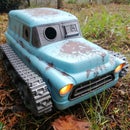
A replacement body for the OpenRC F1 by Daniel Norée, designed to reuse all of the original mechanical pieces and chassis, but provide a whole new look. I also took pains to make the printing simple and keep the assembly process similar to the original. Huge thanks to Daniel for releasing his project in the first place, and inspiring so many builders and printerers!
This insane creation was inspired by a number of things, including a real car which itself was based on a rendering by Aaron Beck, both of which came flooding back to me when I absentmindedly set my rat rod grille design down on my openRC F1.
If you haven't already printed all of the original F1 parts then you will need to print the chassis, front arms and wheels, rear axle/gear and wheels from Daniel's original design. The attached BOM (Bill of Materials) in step 3 elaborates.
If you like this stuff please consider leaving a tip on Myminifactory, becoming a patreon or even just uploading pictures of your prints and sharing them with credit, it all helps! There is also an Ossum facebook page/group to share your prints and questions in, or Instagram to follow progress on new projects.
Get the STL files
(please see step 3 for what to print)
Original Files from OpenRC F1
Ossum RaceRod Files
Option 1: High Octane Towing
Option 2 : Rapid Ordnance Delivery
Supplies
Screws
This list of screws is not as arduous as it seems, you can swap out many of the M3x10 for longer, consolidating on M3x12. Looking at the requirements per step will make it clearer, this list is really more to get a ballpark figure, since it can very depending on build configuration too
- 3pcs – Round/Cap screws M3x8
- 2-4pcs – Cap screws M3x12 (or longer)
- 10pcs – Countersunk screws M3x8
- 7pc – Countersunk screws M3x10 (or longer)
- 2pcs – Countersunk screws M3x12
- 2pc – Countersunk screws M3x18 (or longer)
plus, depending on build:
- 2pc – Cap screws M3x12 (up to 16mm)
OR
- 2pc – Countersunk screws M3x12 (up to 16mm)
Nuts
- 21pcs – M3 nuts (mount brackets to chassis)
Bearings
- 4pcs – Bearing 8x12x3,5
- 2pcs – Bearings 12x18x4
Electronics
You can use whatever you like, but for reference, I used:
- Hobbywing 1060 ESC
- RC4GS Transmitter
- Assorted 2S LiPo Batteries
- Assorted Servos (see the openRC F1 pages for deets)
Step 1: Tools Required


3D Printer
Quite obviously you will need a 3D printer, but which one? In reality, though there are many parts, none of them are challenging prints, due to careful design. I used three printers for my project
Far and away the simplest and most reliable printer I have for large PLA/PETG parts, all of the silver and bronze PLA was printed on the DP200.
This printer really excels at the small nylon and mid-sized ABS parts. All green suspension parts were printed in nylon and the black/hot-pink is ABS.
This printer continues to be my go-to for flexibles, the black/white/blue TPU tyres were printed on it.
Other Tools
- Screwdriver/Allen key
- Needlenose Pliers (to press in nuts)
- Craft Knife/Scalpel (for cleaning up prints)
- Soldering Iron (for soldering and for pushing stubborn nuts into their recesses)
Step 2: Parts to Print and Materials to Use


What To Print
The big question, what is needed from the original F1 car and what is from the new Ossum files? Please take a look at the BOM (Bill of Materials) attached to this step, it lists how many of each part is required and has a hyperlink to download them.
Print Materials
Body/Chassis
This project doesn't require any very specific material properties, whatever you can print easily is probably the best for the large parts. On my silver/pink build the silver is PLA and the pink is ABS.
Front Suspension
If you can manage it then Nylon is great for the front suspension setup, since it is the most likely to take impacts. I do however believe that Daniel designed the whole original to be printed in PLA though, so it can work just fine.
Drive Gears
The spur/pinion gears are best printed in nylon for toughness (my preference) or PLA for hardness.
Tyres (or Tires if you hail from the USA)
The tyres can be printed in TPU or other flexible filament. Be warned that printed tyres are more of a gimmick to say the whole car is printed (which I appreciate!), if you really want performance them one of the alternative rims that use rubber RC tyres are far better.
See the next step regarding printing whitewalls.
For more details on the original parts I recommend looking at the OpenRC F1 instructable and watching the build guide.
The only part of my design that requires support is the cab (mostly for the windows, but the underside of the hood cowl can do with them too). Set the support threshold to >60 degrees since you don't want any supports in the intakes.
The roof insert prints vertically on its rear edge. The assembly is all done in the same method as the OpenRC F1, with M3 bolts and captive nuts.

Step 3: Chassis and Front Suspension


This part of the steering and suspension is exactly as described in Daniel's build videos, which I have linked below. No new parts are required to be printed.
Non-Printed Parts Required
- 3pcs – Roundhead screws M3x8
- 2pcs – Countersunk screws M3x8
- 2pcs – Countersunk screws M3x12
- 2pcs – M3 nuts
I found an alternate knuckle for the front steering that I like, it takes a screw through it for strength and has little bumps which form steering limits, this does however require two 25mm long M3 screws per side.
OpenRC F1 Build Videos
Step 4: Rear Axle and Motor Mount


At this stage we diverge slightly from the stock OpenRC F1 car. Although the axle and gears are the same the motor mounts are slightly different.
These motor mounts provide support for whichever rear assembly your chose (bombs or truck bed) as well as making the body and chassis a rigid assembly.
Axle Offset
The mounts are compatible between the two designs. I have provided a version of each axle holder which positions the axle in the stock position, but I recommend the extra offset (+5mm or +6mm), in order to run larger tyres if desired.
Alternate Bombs
If you decide to go for the "Rapid Ordnance Delivery" Bomb truck option you may want to print these alternate version bombs/rockets too.
Non-printed Parts Required
- 2pcs – Bearings 12x18x4
- 4pcs – Countersunk screws M3x8
- 10pcs – M3 nuts (mount brackets to chassis)
Open RC F1 Build Video
Step 5: Printing Grille, Hood, Body


Grille
The grille is printed vertically, without support.
Roof Insert
The roof insert is printed vertically, on its back edge, without support
Hood (split or single-piece)
There are two hood option, either a single piece which is designed to be printed vertically on its back edge (without support), or a 3 piece that is printed horizontally (with support for the wheel arches if desired).
Single Piece Hood advantages over Split Design
- Simple one piece print
- Simple assembly
- Requires 125mm vertical print (too tall for my Robox Dual)
- Works with any of the grille designs (split hood requires some extra clearance)
Split Hood advantages over Single Piece
- Print orientation is same as body resulting in a uniform appearance (see my bronze build for the converse).
- Can print center in a different colour
Body
The body is printed in its upright orientation, and requires support material for the windows. Depending on your overhang capability you might even get away without any(as I have done by mistake). You will want to avoid getting support material in the intakes or the various little holes for screws and nuts.
Brace, integrated or not?
There are two options of the body, one marked as having an "integrated brace" and one where the brace is separate.
I would go for the integrated option unless you have a reason not to, since it simplifies supports and assembly. I only decided to keep the "separate" option in case folk want to use the body for other builds where the clearance is required.
Rear, Bombs or Bed
The rear option of bombs or truck bed are purely aesthetic, simply choose one and go with it
Truck Bed (link)
The bed prints in its upright orientation (without support)
The insert prints vertically (without support) - choose the orientation that does not have an overhang!
Bomb Carrier (link)
The bomb rack prints in its upright position (without support)
The bombs print standing on their tails (without support) Try this option for some extra variety
Step 6: Assemble the Body


The assembly of the body is fairly simple, following the same ideology of the openRC F1 it uses captive M3 nuts and bolts.
If you have any trouble getting the nuts into the holes then gently pressing them in with a hot soldering iron is an excellent solution.It also make them stay put which is super helpful!
As usual, the pictures speak loudest, so please peruse the gallery attached to this step
Grille
- 1pc – Countersunk screw M3x10 (or longer)
- 1pc – M3 nut
Insert the nut into the grille, fasten the grille to the base plate with a countersunk screw
Body
- 4pc – Countersunk screws M3x10 (or longer)
- 4pc – Cap screws M3x12 (or longer) (two is enough)
- 6pc – M3 nuts
Insert nuts into all the hexagonal recesses of the body (much easier before it is mounted)
There are provisions for mounting a dashboard, but I have not yet designed one, so no need to mount those nuts.
Fasten the body to the base plates with the four M3x10mm countersunk screws
Fasten the body to the axle mounts with the four M3x12 cap screws (two is actually more than enough)
Hood
- 2pc – Countersunk screws M3x10 (or longer)
- 2pc – Countersunk screws M3x18 (or longer)
- 2pc – M3 nuts
Clip the hood over the body and grille, then use the two short (>=10mm) screws to fasten it to the grille and the two long (>=18mm) screws to fasten it to the body.
Roof
The roof simply clips in place, rear edge first.
Rear (Bomb Option)
- 2pc – Cap screws M3x12 (up to 16mm)
The bomb rack is mounted to the axle holders, right through the flat bed (holding it in place) by an M3x12 (up to M3x16) cap screw on each side. See the section view attached to this step for detail.
Rear (Truck Option)
- 2pc – Cap screws M3x12 (up to 16mm)
The truck bed is mounted to the axle holder with an M3x12mm countersunk screw on each side.
Step 7: Printing Whitewall Tyres


If you've decided that you want to print tyres rather than using rubber RC tyres for traction, then you may as well go the whole hog and print some sexy whitewalls!
I had a sample of white rigid.ink TPU that I saved about a year for this exact purpose.
It is as simple as switching filaments for the last few layers. You can do it 100% manually, but I chose to use Craftware to insert a pause at layer 172 (just make sure you use the Gcode preview of your slicer to ensure you are at the correct layer)
Step 8: Mounting Wheels


If you have opted for printed wheels then now is a good time to add them!
Simply press the printed tyres onto the rims, press the rims onto the axle and fasten that all in place by screwing the "locknut" print onto the end of the axle with a 8mm countersunk screw. However, I have never needed to use a screw yet, since the fit is usually quite tight. More details in OpenRC F1 build guide step 7.
Non-Printed Parts
- 4pcs – Countersunk screws M3x8
- 4pcs – Bearing 8x12x3,5
OpenRC F1 Build Video
Step 9: Community Showcase!


Thank you!
I absolutely love seeing the builds that people complete using my designs, it really makes me feel that the countless hours I spend doing these things are more worthwhile when they are amortized over multiple people's enjoyment, so please be sure to upload yours to show me!
On Instructables you can post an "I made this"
On Myminifactory you can share a "community print"
Otherwise share in my Ossum Facebook Group
Or Tag @ossumdesigns on Instagram
Credits to:
RC Tommy for the gold and red ones, with snout headlights
Denis Visser for the Green Sparkle
The Printing Dutchman For the Grey and Green

Participated in the
CNC Contest


