

Introduction: Slouch Alert


In this project, you will create a circuit to alert you when you slouch. The circuit uses the concepts you can learn learn in my free Wearable Electronics Class (Analog Input and Analog Output) lessons. This project notifies you when you are slouching with a little vibration via the vibe motor. This project also uses a snap switch (from Introducing the Switch) as an on/off switch.
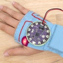
Before you begin, follow the steps to create the handmade flex sensor and snap switch, and begin here with the sensor off the t-shirt. The hook side of the Velcro stays on the t-shirt, holding the sensor's place so you know where to put it when you build the circuit on the t-shirt.
You will need:
- LilyPad Arduino (or similar) microcontroller
- USB cord
- Computer with Arduino software and USB port
- alligator leads
- sewable LED
- LiPo Battery
- Handmade flex sensor with conductive fabric
- Snap switch
- Conductive thread
- Multimeter (optional)
- Paper
- Pen
- Pencil
- Felt
- Fabric marker
- Soft measuring tape
- Fabric glue (Fabri-Tac)
- Ruler
- Straight pins
- Sew-on snaps
- All-purpose thread
- Hand sewing needle
- Scissors
- Heat 'n' Bond
- Iron & ironing board
- Sticky back Velcro tape
Step 1: Build Circuit

Connect the circuit as illustrated.
flex sensor --> power (+)
flex sensor --> resistor
resistor (same side the flex is connected to) --> pin A5
resistor --> ground (-)
snap switch --> pin 2
snap switch (-) --> ground (-)
vibe board power (+) --> pin 11
vibe board ground (-) --> ground (-)

There will be three clips connected to the ground (-) pin. In the Analog Output lesson, you used half of the snap switch to break it out to make it easier to clip to. Three is the max amount you can get on there so you do not necessarily need it now. However, since you are using the switch for this project you may want to make yourself another one for future use!
Attachments

Step 2: Upload Code

Open the previously downloaded sketch, upload it to your board and open the serial monitor.

Let's test to see if the circuit is connected correctly and working. Snap the switch closed. The values coming from your flex sensor should start streaming to the monitor.
If the sensor is more than 400 "slouch" will be printed in the monitor and the vibe motor will go on.

How Does it Work?
When the sketch loads and is running it reads the pin the switch is on to see if it's closed or open. When it is closed it reads the sensor values and when the sensor goes past a threshold it knows that you are slouching and turns the vibe motor on to indicate that you should straighten up!
All of the code in the sketch is stuff you have used in the previous Arduino lessons. The only new lines are the ones that are created in the if() statement.
In this if() statement we are saying that if the average of the sensor readings go above 400, print "slouch" in the serial monitor and turn the vibe board on. Else, if the board is below 400, turn the board off. if (average > 400) {
Serial.println("slouch");
digitalWrite(vibeBoard, HIGH);
delay(1); // delay in between reads for stability
} else {
digitalWrite(vibeBoard, LOW);
}
}
400 is the threshold and can be changed anytime if you feel like the threshold is too high or too low. We will go over how to calibrate the sensor once you can wear it. The best way to calibrate is when the sensor is being used as it is supposed to be. The values it gives you now will be different than when you put it on the body to wear it.
Step 3: Making It Mobile
The circuit is not ready to be untethered quite yet. This is because you still need to be able to read the sensor values coming from the board through the serial connection the board has with your computer via the USB cord. You still have calibration to do and since the board is powered by the USB cord you do not need the battery while it's connected.
Test With Battery
However, it is still a good idea to test the circuit with the battery. Go ahead and turn the board off and unplug the USB cord. Grab the battery and plug it in. Turn the board back on and wait about 30 seconds. Bend the sensor and feel the vibe motor go on. When you feel it that means it has crossed that threshold of 400. Even though you can not see the values you still know it's crossing that line.
Step 4: Record Connections & Disconnect


Record your circuit connections the same way you did for the Hi-5 Collector in the Hi-5 Collector Circuit lesson. As a refresher, here are the three ways to record a circuit.
1) Draw a schematic diagram.
2) Create your own drawing.
3) Write it down.
Double check the recording to make sure you wrote the connections down correctly.
Once you have recorded the circuit, you are ready to safely take the circuit off the alligator leads. After you disconnect everything, you will have six components including the battery.
1 x LiPo battery
1 x LilyPad USB
1 x snap switch
1 x handmade flex sensor
1 x vibe board
1 x resistor
Share your final circuit clipped together and in action below along with your diagram. In the next step, we will be transferring this circuit to the t-shirt!
Step 5: Draw Circuit on T-Shirt


Now is the time to rebuild your circuit onto the t-shirt.
I've included a diagram using the upper center back with the flex sensor on the left shoulder and the switch on the right. You should already know where the sensor should be placed based on your findings from the Read Body Movements lesson. Use the diagrams to place your components or feel free to make your own layout based on your discoveries. Make sure to snap a photo to share at the end of this lesson.
Clip the battery into the JST connector on the LilyPad USB. Place the LilyPad, vibe board, resistor and battery on the back of the t-shirt. Center everything and put it close to the neckline. The upper back is a good out-of-the-way spot to put protruding components because it's a relatively flat part of the body that doesn't come in contact with other things that often. The other place is the upper torso by the neckline or around the shoulder area. Experiment with placement!

Things to take into consideration when placing your components:
1) Visualize your conductive paths. When possible, do not put a component in a place that will create overlapping paths. There are two points on the diagram where paths do overlap, I will show you how to deal with those in this lesson.
2) Leave room to sew down and around components
3) Are any components polarized?


Start on the front of the t-shirt.
Put the flex sensor back onto the velcro that was left on the t-shirt. This Velcro needs to be removed before you attach the sensor to the shirt. Carefully peel the sensor back, remove the Velcro underneath and replace the sensor.


Use the fabric pen to trace around the flex sensor and snap switch. Make a dot where each lead of the sensor hits the t-shirt.


Flip the t-shirt over and trace around the LilyPad USB, vibe board and resistor. Make a dot through each hole of the vibe board and mark the ground (-) and power (+) side.
Mark where to connect to the resistor, if your resistor is not on a felt breakout make a mark through each curled-up lead.
On the LilyPad USB mark pin 2, power (+), ground (-), pin A5, and pin 11. Since there is a dark design beneath where my LilyPad is going I used some masking tape to make my marks on.


When the Hi-5 Collector was built the snaps were sewn on first since you needed to sew the traces to them with conductive thread. This time, you will mark and build the circuit first because the snaps will be placed over the ends of the traces and then sewn to them afterwards.
First, draw the traces that connect the sensor and the resistor to the LilyPad USB.
Then draw the one side of the resistor to the ground (-) pin of the LilyPad.

Draw the other side of the resistor to analog input pin A5.

Draw one lead of the sensor to the same side of the resistor that is connected to pin A5.

Connect the remaining sensor lead to the power (+) pin of the LilyPad.

Now, onto the vibe board. It only has two connections that need to be made.
The power (+) pin of the vibe board to pin 11.

The ground (-) pin of the vibe board to ground (-) of the LilyPad. This trace goes straight down then crosses the trace that goes from the sensor to the power (+) pin. This is ok, I will show you a way to avoid a short circuit when we start building the circuit out of iron-on conductive fabric.


Keep the t-shirt laid out with it's back facing up and fold the shoulder back to get to your marks. Put two marks on the bottom halves of each contact. This is where the conductive fabric traces need to connect to.

Draw a trace from the first contact to pin 2 of the LilyPad. You will cross another trace which is ok and will be addressed later on.


You have one more connection to make. The remaining switch contact gets connected to the ground (-) pin of the LilyPad. Draw and end on the vibe board's trace that is connected to ground. Since they both need to be connected to ground they can share a common ground trace. To differentiate the ground connections from the traces that overlap, make two dots where the snap switch connects to the vibe board ground and where the vibe board connects to the resistor ground.


You are done drawing the circuit! You are now ready to build it using iron-on conductive fabric.


Step 6: Iron & Sew Circuit
Cut multiple thin strips of iron-on conductive fabric 1/4" wide using scissors or a rotary cutter

Conductive thread isn't the only conductive fiber-based material you can build soft circuits with, you can also use conductive fabric. Turn your iron on to a medium-high setting, no steam. Let's start with the ground traces. There are two points where traces overlap the ground trace. Let's address this first and get it out of the way.

Cut a piece to the length of your mark.

Iron down the first trace connecting the ground of the LilyPad to the resistor.
For the next piece you need to connect two strips of iron-on conductive fabric. Since you are building one trace, these two pieces need to be electrically connected too. This is very easy to do. Simply, overlap the ends of the two strips and iron one on top of the other. This melts the hot-melt adhesive enough for the two pieces of conductive fabric to touch. Always check your connections with the multimeter! Need a refresher on how to do that? Go back to the Sew a Circuit lesson.

Iron down the second piece of the ground trace connecting ground to the snap switch.

Iron on top of where the two strips overlap to create an electrical connection and to continue the trace.

Cut and iron another strip to continue the trace up towards the snap switch, end at the shoulder.

Make the last connection to the ground pin, which is to the vibe board.
Now is when we address those two points where traces overlap another. When a trace needs to cross another trace you can make sure that there is no potential for a short circuit. All you need to do is make a barrier between the two traces. I call these barriers bridges since they act like one, allowing one trace to safely run over the trace underneath it.
To make a bridge, iron a strip of Heat 'n' Bond to a strip of felt. Peel off the backing when it cools.


Cut a piece long enough to make a bridge over the trace you need to cross. Here I am making a bridge for the sensor trace that connects to power. It needs to go over the ground trace I have already built.

Cut another bridge for the trace that connects the switch the pin 2.

Iron both bridges down.

Place the trace from pin 2 to the switch as you normally would, except now it goes on top of the bridge. Iron down.

Continue the trace up to the shoulder where it will connect to the switch on the front.

Iron down the second trace from the power (+) pin to the sensor.
Continue to iron down the traces to complete the circuit.

Iron the trace from the resistor to pin A5.

Pin 11 to the power (+) pin of the vibe board.

Resistor to flex sensor.

Finish the Power (+) to flex sensor trace if you haven't already.

Lastly, continue the traces to each of the switch's contacts over the shoulder.

Once the circuit is ironed onto the fabric the components get sewn to their corresponding traces. The goal is to make an electrical connection between the trace and the component using conductive thread. Let's start with the flex sensor.
Pick up your flex sensor and notice how one lead faces down and one faces up. The one that faces down will be hard to get to once the sensor is sewn to the t-shirt. To make contact with the lead that faces down before it's sewn down, sew several small stitches of conductive thread through it.


Now the sensor can be put onto the t-shirt. Put the needle aside while the conductive thread is still coming from the lead of the flex sensor. You will pick up the thread and start sewing again in a minute. Take some straight pins and pin the sensor to the t-shirt to keep it in place. Pick the conductive thread back up and stitch through the end of the trace to connect the sensor to it. Finish with a knot and cut the thread. You have made your first sewn connection! Grab your multimeter and test it to see if it's good.


Move on and stitch around the second lead then connect it to its matching trace going to the LilyPad's power (+) pin.


While pinned in place sew the sensor to the t-shirt using a running stitch and regular thread.


If your resistor is on a felt breakout, pin it in place to the t-shirt. Otherwise, hold it down with your thumb and forefinger while you sew it down. Make stitches through each lead of the resistor then onto each trace that you are connecting it to. Remember to check your connections with the multimeter!


Before sewing the vibe board down, turn it over and look at the bottom. The power and ground pins have a metal underside. This comes in handy when making connections since the metal can make an electrical connection just by sitting on top of the trace.
Overlap the metal pins with their matching traces (it's polarized!) and sew down with conductive thread using small and tight stitches.

The power and ground pins extend to the bottom of the vibe board.

Place the metal pads over the traces for a better electrical connection. Sew down using small and tight stitches.

Before you sew the switch to its traces, the two contacts need to be sewn to the t-shirt. Pin the two switch halves to the fabric. While pinned, check to make sure that when the top half is folded down it can reach and snap into the bottom half.

Use a running stitch to sew the switch down. Sew the top half about a quarter of the way up so it can fold down and snap into the bottom half.


Now you are ready to make the electrical connections. Grab your conductive thread and sew each contact to its trace.


The circuit is complete! Well... almost. :)
The snaps still need to be sewn down. Grab the LilyPad, line up the pins 11, A5, 2, power and ground with the fabric traces and mark where the center of the snaps hit the t-shirt.

Center each snap over the marks and sew down using regular thread. The snap should overlap the end of the trace. After each snap is sewn with regular thread use conductive thread to finish connecting each snap to their trace. Check all the connections with the multimeter.


Step 7: Finishing the Circuit


One last thing, you are almost there!
Snap the LilyPad onto the shirt and plug the LiPo battery into the board. Place it directly below the LilyPad and find a spot where it fits and is centered.
Cut a 2.25" x 2.5" rectangle for the pocket and pin it over the battery. Use a running stitch to sew the pocket to the t-shirt.


Go to the inside of the t-shirt where all the conductive thread knots are. Tighten the knots up, put some glue on them and wait for them to dry. Use the glue to cover all the other exposed stitches of conductive thread inside the shirt. Cut off all the conductive thread and regular thread tails.
There is no step to cover the outside of the circuit, it is left bare! I really like the aesthetic of ironed on circuits, what do you think? Of course, if you choose to protect it you can use any of the learned techniques or come up with your own!

You are done! Woohoo! Great job. Make sure to use the multimeter on the continuity setting to test all of your ironed and sewn connections if you haven't already.

Step 8: Test & Calibrate

Congratulations! The slouch alert is done! All that remains is to test and play with the slouch alert circuit.


In the previous step, you finished the circuit and tested your connections along the way. It is now time to test the circuit again to make sure it's working before you try it on. The more you test a circuit throughout the creation process, the less amount of steps you need to backtrack once the circuit stops working.
Instead of using the battery let's test it with the USB cord plugged in. This way we can see the sensor's values and know if the sensor is working properly and whether the vibe board is turning on when it is supposed to.
Open Arduino, plug the in the USB cord and turn the board on. Open the slouchAlert sketch. This sketch was already uploaded, so no need to hit upload again. Remember that the sensor won't be read until the snap switch is closed so when you open the serial monitor there won't be any values printing in the monitor. Go ahead and close the switch and watch the values jump onto the screen. Press or bend the flex sensor to make it hit the threshold of 400. The word "slouch" will print in the monitor and the vibe board will go on.
Now you know the circuit is working but you will need to test the sensor while it's on too. Right now the value for the flex sensor to hit that tells you whether you are slouching or not is 400. This is the default and will change based on what you read in the serial monitor once the sensor in on and you are you slouching.
Turn the LilyPad USB off. With the board still plugged into the computer put the t-shirt on. If this proves to be too difficult, unplug the cord from the computer, put the shirt on then replug the USB cord. Turn the LilyPad board back on.


Open the serial monitor while the slouchAlert sketch is open and observe the sensor's values. Slouch and straighten like you did in the Read Body Movement lesson of my Wearable Electronics Class to see if the current threshold works for you. The threshold right now is 400. You can see below where it states that in the code.
As a refresher let's go over where this is found in the sketch again. Below is the part of the code that says - if the sensor value is more than 400 turn the vibe on and print "slouch" in the serial monitor. Otherwise, turn the vibe board off.
If it's already above 400 and detecting a slouch while you are straight you need to raise the threshold. If it's difficult to detect to a slouch lower this number.
if (average > 400) {
        Serial.println("slouch");
        digitalWrite(vibeBoard, HIGH);
        delay(1);
      } else {
        digitalWrite(vibeBoard, LOW);
      }
Step 9: Wear It and Going Further

Now is the time for the project to become mobile! The circuit is done, tested, and the sensor is calibrated. Plug the battery in if it isn't already and unplug the USB cord. The circuit is now untethered and you can walk away from the computer! Test it out and make sure to take a picture to share in the comments!
Now your shirt will vibrate to remind you not to slouch! To add audio to this project, continue on in my free Wearable Electronics Class to trigger sounds on your computer by using the LilyPad Arduino as a keyboard.
Also consider trying some of our other free classes, like Arduino, Electronics, Raspberry Pi, Internet of Things, and more!


![Tim's Mechanical Spider Leg [LU9685-20CU]](https://content.instructables.com/FFB/5R4I/LVKZ6G6R/FFB5R4ILVKZ6G6R.png?auto=webp&crop=1.2%3A1&frame=1&width=306)


