

Introduction: Solar Powered WiFi Weather Station V4.0


In this Instructable, we will learn how to make a Solar-powered wireless weather station by using an ESP32 and LoRa module and a few common weather sensors available in the market. The weather station is fully solar-powered, so no need to worry about the external power supply. You can install it in a remote place without laying long cables to provide power.
I have earlier posted three Instructables on Weather Stations ( Version -1.0, Version-2.0, and Version-3.0), you may go through them. The V4.0 is made as per my earlier commitment for including the following features in V3.0:
1. Software for Implementing ESPHome and Home Assistant
2. Software for implementing MQTT
3. Optimizing the Power Consumption
4. Implementing LORA communication ( Probably in V4.0 )
Weather Station V4.0 is an affordable weather station for various applications like smart agriculture, smart city, solar plants, construction site, etc. It consists of two nodes, the Sender Node will be deployed in the field ( where the internet is not available ) and the Receiver Node will be kept indoors where the internet is available for uploading the weather data to the internet.
The main goal of this project is to read the weather parameters by using various sensors, process the data through an ESP32, and then transmit them through the LoRa module. The receiver LoRa unit will collect the data from the Sender node and uploads it to the Server for monitoring and analysis purpose.
The received data can be observed in multiple ways:
1. Monitor the data through e-Ink Paper Display
2. Integration with Home Assistant / ESPHome
3. Upload the data to Thingspeak and monitor the logged data in a graphical format.
4. Monitor the data on smartphones through the Blynk App.
My Book : DIY Off-Grid Solar Power for Everyone
You can order my Book on Off-Grid Solar Power from Amazon
Support me On Patreon:
If you enjoy my work here on Instructables, consider joining my Patreon, it will be a great help for me to make more interesting projects in the future.
Patreon Link:https://www.patreon.com/opengreenenergy
Supplies
COMPONENTS USED: 1×18650 Battery Holder
- 6×Capacitor_SMD_0805 -10uF ( Amazon )
- 5×Capacitor_SMD_0805 -0.1uF ( Amazon )
- 2×Capacitor_SMD_0805 -1uF ( Amazon )
- 3×LED_SMD _0805 - Green, Blue, Red ( Amazon )
- 1×TVS Diode - SMF5.0CA
- 1×Schottky Diode - SS24 ( Amazon )
- 1×Screw Terminal - KF350-3.5-2P
- 2×RJ11 -6P6C connectors
- 7× 4P male headers ( Amazon )
- 1×8P male header ( Amazon )
- 1×USB-C Port ( Amazon)
- 1×ESP32-WROOM32-U ( LCSC )
- 1× Ai Thinker Lora Ra-02 ( LCSC )
- 2×Transistors- MMBT3904 ( Amazon )
- 2×MOSFETs - SI2301S
- 6×Resistor_SMD_0805 - 10K ( Amazon )
- 2×Resistor_SMD_0805 - 200K ( Amazon )
- 5×Resistor_SMD_0805 - 100K ( Amazon )
- 1×Resistor_SMD_0805 - 50K ( Amazon )
- 1×Resistor_SMD_0805 - 2K ( Amazon )
- 3×Resistor_SMD_0805 - 1K ( Amazon )
- 5×Resistor_SMD_0805 - 4.7K ( Amazon )
- 2×Resistor_SMD_0805 - 5.1K ( Amazon )
- 2×SMD Button switches ( Amazon )
- 1×IC -LP4060S ( LCSC )
- 1×IC- AP6685 ( LCSC )
- 1×LDO - XC6220B331MR ( LCSC )
- 1×3 pin Screw Terminal - KF350-3.5-3P
- 1×ESD Diode - USBLC6-4SC6
- 1×LiPo Battery JST Connector
- 1×SMD Power Switch
- Solar Panel -130mm ( PCBWay )
Download the BOM and other files from PCBWay
Step 1: Power Supply

If you are planning to install the weather station at a remote location like your farmhouse, you may not get access to the power grid to run the weather station. To run the station continuously, there must be a continuous power supply otherwise the system will not work. The best way to provide continuous power to the circuit is by using a battery. But in the case of the battery, after some days of running, its juice will run out, and it is a really difficult job to go there and charge it. So a solar charging circuit was proposed to use free energy from the sun to charge the battery and power the PCB board.
Li-Ion/LiPo Battery Charger:
The battery is charged from a Solar panel through an LP4060 charging IC. The charger circuit charges the battery by taking power generated from the solar panel. It is based on a lithium-ion battery charger IC LP4060. It is a complete constant-current/constant-voltage linear charger for a single-cell lithium-ion battery. It uses only a few external components like resistors ( R6 ) and capacitors ( C1 & C12 ). The circuit is based on the application circuit given in the datasheet.
The CHG_STAT LED ( D1 ) is used to indicate the battery charging status, it will turn off when the charging is finished. You can enable this LED by shorting the jumper JP2.
Battery Protection:
The Battery Protection Circuit provides various protections to the Li-Ion battery. The circuit is based on IC - AP6685 which contains internal power MOSFET, high-accuracy voltage detection circuits, and delay circuits. The IC has the following protections inbuilt:
1. Reverse polarity protection
2. Over Charge Protection
3. Over-Discharge Protection
4. Load short circuit protection
The circuit diagram for both the charger and protection circuits is derived from their datasheets. The datasheets are attached below.
1. LP4060
2. AP6685
USB-C Input:
USB-C port is used for faster charging of Lithium Ion Battery. The 18650 battery outputs 4.2V when fully charged. The resistors R25 and R26 are used as pull-down resistors.
3.3V Power Supply:
The operating voltage of the ESP32 and LoRa module is 3.3V whereas the fully charged battery voltage is 4.2V. So we have to step down the battery voltage from 4.2V to 3.3V, which can easily be done by a linear voltage regulator but unfortunately, it is not at all recommended for this project. Because all the linear regulators require an input voltage at least some minimum amount higher than the desired output voltage. That minimum amount is called the dropout voltage. Due to this reason when the battery voltage drops to around 3.7V, the linear voltage regulator will not be able to maintain the required voltage ( 3.3V ).
The solution to the above problem is to use a low-dropout or LDO regulator. A low-dropout or LDO regulator is a DC linear regulator which can regulate the output voltage even when the supply voltage is very close to the output voltage. Here we will use an XC6220B331MR LDO for efficiently powering the Circuit.
The capacitors ( C2 and C3 ) are connected to the input and output of the LDO to smooth the voltage peaks.
Step 2: Solar Panel and Battery Voltage Sensing:

The max allowed voltage input to the ADC pin of the ESP32 is around 3.2~3.3V but a fully charged 18650 battery and solar panel voltage are in the range of 4 - 6V. So to measure these voltages we have to step down the voltages by using voltage divider networks.
The battery voltage is sensed by the voltage divider consisting of R2 and R3. Similarly, the solar panel voltage is sensed by the voltage divider consisting of R4 and R5
The voltage divider formula is as follows:
Vbat_sense = (Vbat*R3)/(R2+R3)
Vsol_sense = (Vsol*R5)/(R4+R5)
Step 3: ESP32 Interfacing

The main controller for this project is an ESP32-WROOM32 microcontroller. The 3.3V power supply from LDO is fed to the 3V3 pin of ESP32 with input filter capacitors C7 and C8. The two resistors R10 and R11 are pull-up resistors for the I2C bus. LED D4 with a current limiting resistor R22 is used for indicating the debugging status. A jumper JP1 is used to enable or disable the debug LED. If you need this LED, you have to short the jumper JP1.
The Program port J11 is used for connecting the board with a programmer to upload the firmware.
Step 4: Interfacing With LoRa Module


LoRa is a 'Long Range' low power wireless standard intended for providing a cellular style low data rate communications network. LoRa is ideal for providing intermittent low data rate connectivity over significant distances.
LoRa is a wireless modulation technique derived from Chirp Spread Spectrum (CSS)
technology. It encodes information on radio waves using chirp pulses - similar to the way dolphins and bats communicate! LoRa-modulated transmission is robust against disturbances and can be received across great distances.
Few awesome features of LoRa communication:
- Ultra-low power - LoRaWAN end devices are optimized to operate in low power mode and can last up to 10 years on a single coin cell battery.
- Long range - LoRaWAN gateways can transmit and receive signals over a distance of over 10 kilometers in rural areas and up to 3 kilometers in dense urban areas.
- Deep indoor penetration - LoRaWAN networks can provide deep indoor coverage, and easily cover multi-floor buildings.
The LoRa module has been connected to ESP32 through the SPI protocol.
Deep Shutdown of LoRa:
I have added a power switch circuit by using a MOSFET ( Q2) and transistor ( Q1 ) for a complete shutdown of the LoRa module during sleep mode.
Step 5: Weather Sensors

This Weather Station is a compact weather station that consists of several meteorological sensors that measure most of the useful weather parameters:
1. Internal Temperature (BME280)
2. Humidity (BME280)
3. Barometric Pressure (BME280)
4. External Temperature (DS18B20)
5. Wind Speed ( Sparkfun Weather Meter )
6. Wind Direction ( Sparkfun Weather Meter )
7. Rain Gauge ( Sparkfun Weather Meter )
8. UV Index ( SI1145)
9. Lux Level ( BH1750 )
10. Air Quality Sensor ( PMS5003)
Apart from the Weather Sensors, I have added an additional port for the Soil Temperature and Humidity sensor, which is useful for agriculture.
I have also added some spare I2C ports to connect sensors as per the user's preference.
ESD Protection:
As the wind and Rain sensors are exposed to the environment, an ESD protection diode ( U7 ) is used to protect the board from unwanted voltage surges.
Complete Shutdown of all the sensors:
I have added a power switch similar to the LoRa module for a complete shutdown of all the sensors. It will reduce power consumption significantly.
Step 6: Complete Schematic Diagram


Here is the final schematic for the Weather Station V4.0. It has two sheets, the first sheet is related to the charger, power supply, and ESP32 board. The second sheet is on the interfacing of the LoRa module with ESP32 and all the weather sensors.
Step 7: Wind Vane ( Wind Direction Sensor)


The wind vane indicates the direction that the wind is blowing. It is the most complex of the sensors in the Sparkfun Weather Sensor Kit. It has eight reed switches, each connected to a different resistor. As the wind vane rotates, a magnet closes the reed switches and may close two at a time due to their proximity to each other, allowing up to 16 different positions to be indicated. However, in testing the unit, I never could make the device close two switches at once, so although it might be possible theoretically to measure 16 directions, I only get eight. The software takes 16 directions into account, just in case.
An external resistor can be used to form a voltage divider, producing a voltage output that can be measured with an analog to digital converter, on your the microcontroller allows you to determine the direction of the wind vane pointer.
To measure voltage output, I have used a 10kohm external resistor to form a voltage divider with the wind vane resistor ( Rvane). The 10K resistor is connected to 3.3V as shown in the above figure. Then, I connect the middle of the divider to the ESP32 ADC pin (GPIO 35), measure the voltage, and by referring to the table shown above, convert it to the wind direction.
The reed switches and resistor arrangement are shown in the above picture. Resistance values for all 16 possible positions are given in the table.
When the wind vane pointer falls in between two switches, the resistance value is considered as the equivalent resistance between the two adjacent resistances. In this situation, the vane’s magnet activates two switches simultaneously, as result they are connected in parallel.
Example:
When the wind vane pointer falls in between the Switches S1 and S2, the equivalent resistance is determined by the following formula:
Rvane = R1x R2 / ( R1+R2 ) = 33 x 8.2 / ( 33 +8.2 ) = 6.57K
Since the values outputted by the wind vane are based on degrees, you can, in theory, have any value represent any direction. However, it is recommend having the value at degree 0 represent North for ease of use.
Step 8: Anemometer ( Wind Speed Sensor)

The wind speed sensor is a cup-type anemometer that measures wind speed by closing a contact as a magnet moves past a reed switch. As per the datasheet, a wind speed of 2.4km/h (1.4912 mph) causes the switch to close once per second. The anemometer switch is connected to the inner two conductors of the RJ 11 cable shared by the anemometer and wind vane (pins 2 and 3).
The Anemometer is connected to the ESP32 GPIO pin 14 and GND. After that, all we need to do then is to monitor for button presses which are pretty straightforward. We can use the pin interrupts method to monitor the button press ( tips). When the reed switch closes the circuit (pressing the button), it triggers a software event.
If you want to make your own wind sensor, then read this nice Instructable
These are a few more 3D-printed Wind Sensors:
1. Anemometer
Step 9: Rain Gauge ( Rain Fall Sensor )


Here I have used a most common type of Rain Sensor which is called a Tipping Bucket rain gauge. Basically, there's a little see-saw shape tipper bucket inside the sensor ( see the above picture ). The rain fills up a bucket on one end and it tips over so that it empties and the bucket on the other side starts to fill. Each time the bucket tips it passes a magnet over a reed switch making a momentary electrical connection. The buckets are calibrated to a volume of water, which means if we can count how many times the switch closes we can calculate how much rainfall there's been.
Much like the wind speed gauge, the rainfall gauge generates ticks to tally the amount of rain that has fallen. Count ticks to determine how much rain has fallen recently. Each tick represents 0.011" ( 0.28mm ) of rainfall. This sensor is connected to pin 25 of the ESP32.
The rain gauge that I have used here is from Sparkfun. It has an RJ-11 plug on the end, you can directly plug it into the Weather Station V3.0 PCB.
You can make your 3D-printed Rain Gauge by following this article
Measuring The Rainfall:
we have discussed that each time the bucket tips, it passes a magnet over a reed switch making a momentary electrical connection. Here each tip of the bucket in the rain gauge can be assumed as a button press. We can easily then connect the gauge as if it were a button.
The rain gauge is connected to the ESP GPIO pin 25 and GND. After that, all we need to do then is to monitor for button presses which is pretty straight forward. We can use the pin interrupts method to monitor the button press ( tips). When the reed switch closes the circuit (pressing the button, the bucket tipping), it triggers a software event.
Here I am using attachInterrupt()to monitor the number of tips. You can find the details on Arduino Page.
Step 10: Monitoring Pressure ,Temperature and Humidity by BME280


In the earlier days, weather parameters like ambient temperature, humidity, and barometric pressure were measured with separate analog instruments: thermometer, hygrometer, and barometer. But today the market is flooded with cheap and efficient digital sensors that can be used to measure a variety of environmental parameters. The best examples are sensors like DHT11, DHT 22, BMP180, BMP/E280, etc.
In this project, we will use BMP280 / BME280 sensor.
BMP280: BMP280 is a sophisticated sensor that very accurately measures barometric pressure and temperature with reasonable accuracy. The BME280 is the next generation of sensors from Bosch and is the upgrade to the BMP085/BMP180/BMP183 - with a low altitude noise of 0.25m and the same fast conversion time. The advantage of this sensor is that it can use either I2C or SPI for communication with the microcontroller. For simple easy wiring, I will suggest buying the I2C version board.
BME280: The new BME280 sensor is an environmental sensor with temperature, barometric pressure, and humidity. The BME280 is the next generation of sensors from Bosch and is the upgrade to the BMP280. This precision sensor from Bosch is the best low-cost sensing solution for measuring humidity with ±3% accuracy, barometric pressure with ±1 hPa absolute accuracy, and temperature with ±1.0°C accuracy. It can be used in both I2C and SPI.
Note: BME280 can measure humidity but BMP280 can't. In the market, BMP280 is also available by the name of BME280. So be sure whether it is a BMP280 or BME280.
You can read this nice article on BME280 for a better understanding.
Step 11: Monitoring UV Index - SI1145 Sensor


The Si1145 is a sensor with a calibrated UV sensing element that can calculate the UV Index. It can communicate via I2C communication (address 0x60). You can hook up this sensor with I2C port in the PCB which is located at the bottom left of the ESP board.
The SI1145 sensor really doesn’t have an actual UV sensor! Instead, it looks at the amount of visible and IR light it receives from the Sun and uses a formula to calculate the UV index, right down to two decimal points.
You can read this article to know more about the UV sensor.
If you need a more accurate measurement of the UV Index, you may use the VEML6070 sensor. Unlike the Si1145, this sensor will not give you UV Index readings. However, the Si1145 does UV Index approximations based on light level, not true UV sensing. The VEML6070 in contrast does have a real light sensor in the UV spectrum.
You can read this tutorial for writing the code and using its library.
Step 12: Monitoring Lux Level - BH1750 Sensor


The BH1750 Ambient Light Sensor Module is based on the digital Ambient Light Sensor IC BH1750FVI developed by ROHM Semiconductor. It is a digital IC with built-in 16-bit illuminance to digital converter.
The output of this sensor is in LUX (lx), so it does not require any further calculations. Lux is the unit to measure Light intensity. It measures the intensity according to the amount of light hitting on a particular area. One lux is equal to one lumen per square meter.
For communication with external devices like ESP32, the BH1750 Ambient Light Sensor IC uses I2C Bus Interface.
Pin Description
VCC – 3.3V to 3.3V
GND – VCC
SCL – SCL
SDA – SCL
ADD – I2C Device Address ( Kept Open )
You can read this instructable for information on the BH1750 light sensor
Step 13: External Temperature Sensor

If you need, you can connect an external temperature sensor like DS18B20 to monitor the ambient temperature. DS18B20 is One Wire interface Temperature sensor manufactured by Dallas Semiconductor Corp. It requires only one digital pin for two-way communication with a microcontroller. I have hooked up this sensor with ESP32 GPIO pin4.
The DS18B20 comes usually in two form factors. One that comes in the TO-92 package looks exactly like an ordinary transistor and another one in a waterproof probe with an extension cable. I have used DS18B20 probe for measuring the temperature. It uses a one-wire protocol to communicate with the ESP32. It can be hooked up to the 3 pin screw terminal on the PCB.
To interface with the DS18B20 temperature sensor, you need to install the One Wire library and the Dallas Temperature library. You can read this article for more details on the DS18B20 sensor.
Step 14: Air Quality Sensor ( PMS5003)


PMS5003 is a kind of digital and universal particle concentration sensor, which can be used to obtain the number of suspended particles in the air, i.e. the concentration of particles, and output of them in the form of digital interface.
PM2.5 and PM10 refer to particulate matter with particle diameters up to 2.5 microns and 10 microns respectively and are among the most dangerous air pollutants. Due to their small size, PM2.5 particles can travel deep into the human lung and cause a variety of health issues; for instance, by triggering asthma attacks or contributing to cardiovascular disease.
High concentrations of dust or PM is a serious health concern. PM2.5 is less than 2.5 microns in diameter, and PM10 is less than 10 microns in diameter. This means a PM10 report includes PM2.5 as well. Both these particles are much smaller than human hair, which is about 70 microns in width.
PM10: Operations such as stone crushing, coal grinding, rotary kilning in the cement industry, and dust on road stirred by moving vehicles can increase PM10 levels. PM10 limit for 24-hour average is 150µg/m3.
PM2.5: This is a result of fine particles produced from all types of combustion, including motor vehicles, thermal power plants, residential wood burning, forest fires, agricultural burning, and other industrial processes. PM2.5 limit for 24-hour average is 35µg/m3.
The Plantower PMS5003 is a low-cost laser particle counter, one of a range of sensors by Plantower that also includes the PMS1003, PMS3003, and PMS7003. PMS5003 is a kind of digital and universal particle concentration sensor, which can be used to obtain the number of suspended particles in the air, i.e. the concentration of particles, and output them in the form of a digital interface. This sensor can be inserted into variable instruments related to the concentration of suspended particles in the air or other environmental improvement equipment to provide correct concentration data in time.
Working Principle
The laser scattering principle is used for such sensors, i.e. produce scattering by using a laser to radiate suspending particles in the air, then collect scattering light to a certain degree, and finally obtain the curve of scattering light change with time. In the end, equivalent particle diameter and the number of particles with different diameters per unit volume can be calculated by microprocessor based on MIE theory.
Pin Diagram:
The pinout diagram is shown above for reference.
Reference: You may go through this nice article on the PMS5003 air quality sensor.
Step 15: Soil Temperature and Humidity Sensor ( SHT30 )


SHT30 is a digital temperature and humidity sensor. This module uses I2C communication and the 2 SCL and SDA pins are used to communicate with this sensor.
The sensor includes a dual-use sensor module from Sensirion in a sintered metal mesh encasing. The casing is weatherproof and will keep water from seeping into the body of the sensor and damaging it, but allows air to pass through so that it can measure the humidity outside.
The SHT30-D sensor has an excellent ±2% relative humidity and ±0.5°C accuracy for most uses. Unlike earlier SHT sensors, this sensor has a true I2C interface.
You can read this tutorial for writing the code and using its library.
Step 16: Ultra Low Power Consumption


The heart of our Weather Station is an ESP32 SOC, a power-hungry chip. When the project is powered by a plug-in wall, you tend not to care too much about power consumption. But if you are going to power your project with batteries, every mA counts.
Our objective is to run the device by using a 18650 Li-Ion battery. To run the ESP32 by using a battery, we have to lower the power consumption. The power consumption can be reduced in the following ways:
1. Software Optimization
2. Hardware Optimization
Software Optimization:
Using Deep Sleep Mode which is the most power-efficient option for the ESP chip. It allows to put the ESP32 into hibernation and saves the battery. You can wake up the ESP at regular intervals to make measurements and publish them.
Hardware Optimization:
The power-consuming components in the PCB are LEDs, ESP32, LoRa, and Sensors. The ESP32 power consumption can be minimized by software optimization. However, we can reduce the power consumption of all other components by optimizing hardware design.
I have considered the following in my hardware design to reduce the power consumption
A. LED jumpers:
You can enable/disable all the 3 LEDs ( DEBUG, CHRG, and POWER ) used in the PCB board by using the jumpers JP1, JP2 and JP3. The default state is in disable condition, but if you need them, bridge the Jumpers by applying solder.
B. Power Switch for LoRa:
I have added a power switch circuit by using a MOSFET ( Q2) and transistor ( Q1 ) for a complete shutdown of the LoRa module during sleep mode. The ESP32 GPIO pin 16 is used to control this power switch.
C. Power Switch for Sensors:
I have added a power switch circuit by using a MOSFET ( Q3) and transistor ( Q4 ) for the complete shutdown of all the sensors during sleep mode ( when no sensor data is to be sent). The ESP32 GPIO pin 26 is used to control this power switch.
Step 17: Receiver Board


The receiver node is designed to receive the weather sensor data sent by the sender node from the field. Then display the received data on various platforms like ThinkSpeak, Blynk App, or on an e-paper display.
I have drawn the receiver schematic on the Autodesk eagle. The main features of the receiver units are:
1. Onboard power supply
2. Charging Circuit for 18650 battery / LiPo Battery
3. I2C headers for hookup sensors to monitor the indoor parameters
4. SPI interface port for connecting an e-paper display.
Update on 12.07.2023
Earlier I have designed a low-power version receiver board ( fully SMD version) but unfortunately, I messed it up. So I have redesigned a simplified version by using a few SMD components and an ESP32 dev board.
Last night, I have tested the new board by using a BME280 sensor and a 4.2" e-paper display.
The following are my observations:
- Sensor data successfully received through LoRa communication
- Parameters are also displayed on e-paper in realtime
- The battery charging circuit is working perfectly
Now you can use this PCB board and write your own custom code. We are working on the dedicated software for the receiver board, I will publish it here when completed. Stay tuned!
You can order the PCB or download the Gerber files from PCBWay
Attachments

Step 18: PCB Design


After finalizing the schematic for boththe Transmitter and Receiver Unit, I designed the PCB for them.
The 3D model of both the transmitter and receiver board is shown above.
The main features of the Transmitter PCB are:
1. 2 Battery Options: Either 18650 battery directly into the slot or LiPo battery through the battery JST connector
2. Solar charging port: " SOLAR PANEL " screw terminal
3. USB-C charging port - USB-C is given for quicker charging of the battery in case of low sunlight for a long time.
4. 6 x I2C ports for hooking up a variety of sensors
5. 2x RJ11 ports for connecting the Wind and Rain Sensor
6. Additional port for Air Quality Sensor ( PMS5003 )
7. Screw the terminal to connect the DS18B20 temperature probe
8. Programming port for uploading the sketch by using a UART serial programmer
Download the PCB Gerber Files from PCBWay
Step 19: Assemble the PCBs


Assemble the PCB by taking reference of the schematic diagram. You can solder the SMD components in many ways like 1. Hot Air Reflow 2. Hot Plate Reflow 3. Re-flow ovens 4. Hand Solder by Soldering Iron
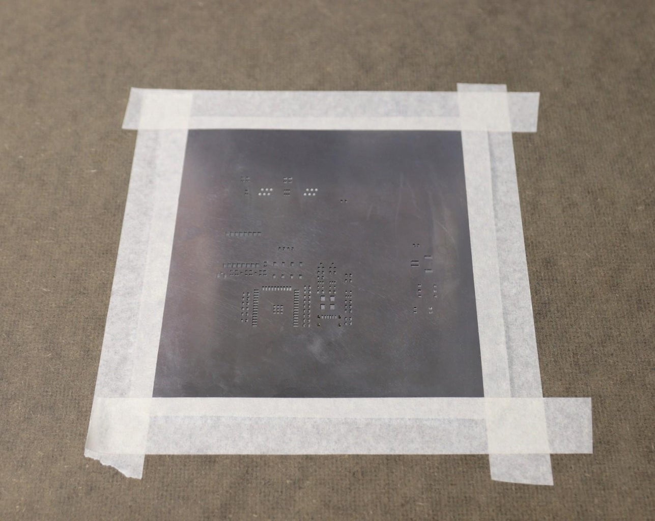
I have used the Hot plate reflow method to solder the components. I stuck the PCB on my table using masking tape and placed the SMD Stencil right on top of the Board. Align the Stencil with the PCB pads and secure it by using masking tape.
Here I am using 63% tin - 37% Lead solder paste. Apply some Solder paste on the stencil and use something flat, like a PCB or credit card to spread the Solder uniformly on the PCB. Remove the Stencil carefully and you can see that the Solder Paste is Uniformly Applied on the Solder pads of the PCB.
Place all the SMD components by using tweezers and place the Board on the Hot Plate. Turn On the hot plate and wait until the Solder paste melts. Then take out the board immediately from the hot plate. The Solder paste melts somewhere around 220 degree Celsius to 250 degree Celsius and this process took me around 3-4 minutes to complete the soldering.
Step 20: How to Program the Transmitter Board


After assembling the transmitter PCB board, I connected my USB to the TTL UART programmer to the programming port. The connections are as follows:
Programmer -----> PCB
3V3 ----> 3V3
Tx----> Rx
Rx----> Tx
GND---> GND
After connecting the programmer to the PCB board, I successfully uploaded the test code. The board is working as expected but I have to press the EN switch to start the execution. This is required only once after uploading the code.
Step 21: Software and Libraries

To use the ESP32 board with the Arduino library, you'll have to use the Arduino IDE with ESP32 board support. If you haven't already done that yet, you can easily install ESP32 Board support to your Arduino IDE by following this tutorial by Sparkfun.
Install Libraries:
Before uploading the code install the following libraries :
1. ESP32
2. Blynk
3. BME280
5. BH1750
6. One Wire
7. Dallas Temperature
How to Install the Libraries?
You can read this tutorial by Sparkfun to install the Arduino libraries.
Software:
A stable software version for both Transmitter and Receiver is released on GitHub Page.
Download the Code for Transmitter ( Base Station ) here
Download the Code for the Receiver Node here.
Your feedback is useful for us, please suggest us for improvement.
Step 22: 3D Printed Stevenson Screen Design


The ideal enclosure for keeping the weather sensors is the Stevenson Screen. A Stevenson screen is an enclosure to shield meteorological sensors against precipitation and direct heat radiation from outside sources, while still allowing air to circulate freely around them.
I have designed a 3D-printed Stevenson screen to keep the weather sensors and PCB board. The enclosure has the following parts:
1. Base part
2. 4 x Middle Rings
3. Top Ring
4. Middle Cover ( Separate the Solar panel from the PCB chamber )
5. Top Cover ( above which a 130 mm circular solar panel will be mounted )
The above parts will be assembled by using 4x M4 rods, it can also be 3D printed.
Download the STL files from Thingiverse
Step 23: 3D Printed the Enclosure


I used my Creality 3D printer and 1.75 mm white PLA filament to print the parts. I will recommend using ABS or PTEG filament instead of using PLA. I have used PLA just for the quick test as I don't have ABS or PTEG filament in my stock.
My print settings are:
Print Speed : 60 mm/s
Layer Height: 0.3mm
Fill Density: 25%
Extruder Temperature: 210 deg C
Bed Temp: 65 deg C
I have printed the files successfully but there are minor issues in the fitting of a few parts like M4 rods, and middle cover, and the top cover. I will adjust it soon.
Step 24: Enclosure Assembling


The first step in assembling the 3D-printed parts is removing the support structure from the main body. You have to do this for the following parts:
- Base
- Middle Cover
- Top Cover
Then the assembling process is very straightforward. First Place the Top Ring on a flat surface upside down and then stack the 4 numbers of middle rings one above the others, then place the base part.
Now join them together by using 4 numbers of M4 rods and secure them using 8 hex nuts as shown in the above picture.
Step 25: Mount the UV Sensor


Solder 4 jumper wires to the 4 pins of the UV sensor as shown in the picture.
Then mount the UV sensor by using two screws and then insert the 4 wires into the hole provided at the center. I will recommend using thinner wire for easier assembly.
Step 26: Connect the Sensors


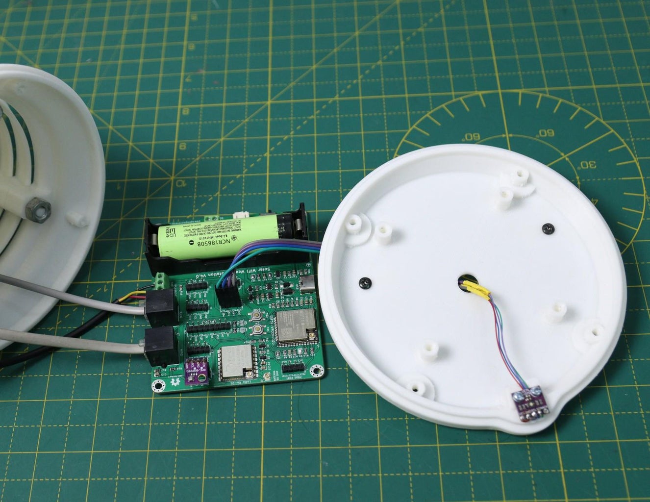

In this step, we will connect all the external sensor cables to the PCB board.
Insert the wind, rain, and temperature sensor ( DS18B20 ) cables into the PCB board. First, pass it through the hole provided in the mounting arm and then into the base part.
The wind and rain sensors shall be connected to the RJ11 port, they are labeled as RAIN and WIND. Similarly, the temperature shall be connected to the DS18B20 screw terminal. The pin names are indicated on the PCB.
Then connect the UV sensor cable to the UV header pins. Be sure you are connecting to the right pin.
Step 27: Prepare the Solar Panel


I have designed a customized solar panel for the enclosure of this weather station. The technical parameters are given below:
- Peak Power (Pmp): 1.6W
- Open Circuit Voltage (Voc): 6.6V
- Short Circuit Current (Isc): 299mA
- Peak Voltage (Vmp): 5.5V
- Peak Current (Imp): 272mA
- Power Tolerance: +/-3%
- Cell Efficiency >= 23%
Now the solar panel is available in the PCBWay store.
Apply a small amount of solder to the two pads of the solar panel. Then solder two 22AWg wires to the terminals.
I have used red wire for the positive terminal and black wire for the negative terminal.
Then pass the terminal wires through the middle cover center hole and connect them to the screw terminal labeled as " SOLAR PANEL".
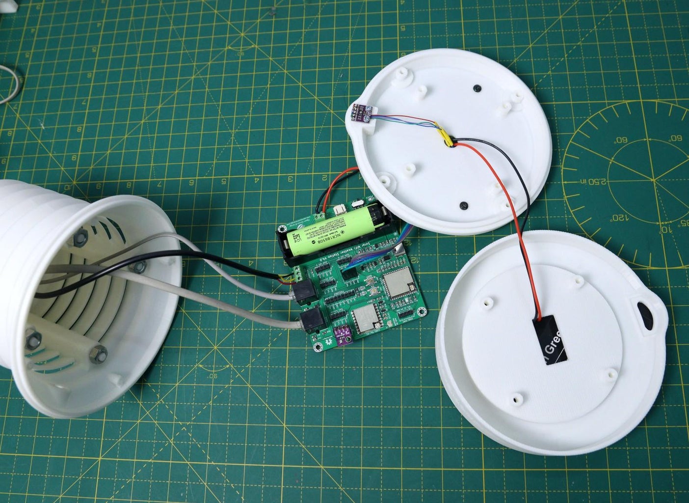
Step 28: Secure the Middle Cover


Align the PCB into the two slots in the PCB holder provided at the base part of the enclosure and then secure it. For a better understanding, you may see the above picture, of how the PCB is installed.
Don't forget to turn on the power switch and press the EN switch before installing the PCB.
Then align the middle cover to the base assembly and secure it by using 4 screws.
Step 29: Close the Top Cover


Before closing the top cover, you have to install the UV sensor cap. The sensor cap must be transparent to pass the sunlight through it and hit on the sensor's active area.
First I printed it using a transparent PLA. However, the result is not satisfactory. So later get it printed in a 3D printing shop using an SLA printer, and the outcome is satisfactory. You can see the side-by-side comparison between the two parts.
Note: If you are not getting access to an SLA printer, you may use a transparent acrylic sheet, the template file (.DXF file) is available on Thingiverse. You may make it by yourself or may laser-cut it.
After installing the UV sensor, you can box up the top cover and secure it by using 4 screws.
The last step is to mount the solar panel. Here I have used double-sided tape but I will recommend using epoxy glue.
Step 30: Weather Station Installation


Once you have confirmed that your weather station PCB along with all the sensors, working perfectly, you need to design and make a mount for it. I have used a wooden pole ( 4cm x 8cm x 300 cm ) to mount the sensors and the 3D-printed Stevenson Screen.
If you purchase the entire Weather Meters Kit, then you don't have to worry about mounting the wind and rain sensor. But if you purchase the independent sensor, you may need some mounting arrangement. I found a nice wind sensor holder from Thingiverse.
First I mount the wind sensors ( Wind Vane and Anemometer ) by using the 3D printed wall mounts. I have installed the wind vane and anemometers by using cable ties. After that, mounted them on the wooden pole by using two screws. You can see the above picture for a better understanding.
Similarly, I mounted the rain sensor on the wooden pole. But the holder used for it is a ready-made one. In the future, I will make a 3D-printed holder for it so you don't have to buy it.
At last, mount the external temperature sensor ( DS18B20 ) on the pole by using cable ties. After installing all the sensors, you have to route all the cables from the sensors to the Stevenson Screen.
Note: Always use good quality cable ties that are specially made for outdoor use ( UV-resistant ).
Now it is time to install the Stevenson Screen which we made earlier. Install the Bottom Mount on the wooden pole by using 4 screws.
Suitable Location for Installation:
The location of your weather station is the most important part of the installation. If your weather station is located under a tree or an overhang, the rainfall data measured by the station will not be correct. If you place your weather station in an alley, you could very well get a wind tunnel effect on the anemometer, resulting in erroneous wind data. If you want to measure sunlight you cannot have the sensor in a shadow. So make sure that there is sufficient clearance around and above the weather station.
You can read this nice article on Weather Station Installation.
Step 31: Conclusion

It took me a lot of time to make the circuit, make the PCB prototype, rectify the errors in the PCB prototype, test the PCB, make the enclosure, etc. So I had not enough time left to complete the project to the extent that I have planned.
I am entering this project in Microcontroller Contest, the deadline is 10.10.2022. So I have no option but to wait and complete everything. The software attached here is a basic test code for the project.
Keep in touch I will update it regularly after achieving all the milestones.
Thanks for reading my Instructable. If you like my project, don't forget to share it.
Comments and feedback are always welcome.

Participated in the
Microcontroller Contest


![Tim's Mechanical Spider Leg [LU9685-20CU]](https://content.instructables.com/FFB/5R4I/LVKZ6G6R/FFB5R4ILVKZ6G6R.png?auto=webp&crop=1.2%3A1&frame=1&width=306)


