

Introduction: Your Own Color Sensor Using LEDs


Did you know that you can make a "cheap" but effective color sensor using some basic components?
This super-easy instructable will guide you to make your own color sensor using a bunch of LEDs and an LDR.
I've managed to make a well arranged, compact , enhanced and relatively thin sensor ( PCB Version ).
This instructable covers up two types of sensor that I've made, the first sensor is the Perf-board version and second is the enhanced SMD version ( 2cm x 2cm x 0.5cm ).
The Perf-board version is ultra-easy to make but if you want the SMD version , you'd require SMD soldering skills ( to solder SOT-23 package transistors ).
Note : In the video , you'll see a board ( Arduino Shield ) that I'm using. That shield is a custom made shield for my upcoming RGB lamp. The process to built it and other details will be covered up in the upcoming Instructable. The Shield basically uses a CD4051 multiplexer to minimize the PWM pins required.
Step 1: Introduction and Part List


These sensors that we're about to build can be used as a substitute to the TCS3200 sensor. Though the TCS3200 is much accurate than these sensors, they are also quite expensive ( ~ 7-10 $ ) than what we're going to make ( max 2 $ ).
SMD version : The SMD version Requires :
1. 2x Red SMD ( 1206 ) - Sparkfun
2. 2x Green SMD ( 1206 ) - Sparkfun
3. 2x Blue SMD ( 1206 ) - Sparkfun
4. 2x White SMD ( 1206 ) - Sparkfun
5. 3cm x 3cm Double sided PCB ( fiberglass epoxy )
6. 1x LDR ( photocell ) - Sparkfun
7. 3x BC847 ( SOT -23 -3 ) - Mouser
8. 1x 10k ( 1206 SMD ) resistor - Sparkfun
9. A 7 pin Ribbon cable
10. Male Headers
Perfboard Version :
1. 1x RGB LED ( SMD / Through hole / piranha ) - SMD ( sparkfun ) , Through Hole ( Sparkfun )
2. 1x LDR ( Photocell ) - Sparkfun
3. 1x 10K resistor
4. 1x 330 ohm Resistor
5. Perfboard - 3cm x 2cm
6. 6-pin Ribbon cable
7. Male Headers
Step 2: Start Building the Board ( Perf-board )


Start making it by soldering the RGB LED on the board
Then Solder the LDR. Finally when the board is soldered with LDR and LED , cut it along the edges of LDR and LED ( leave some space for Resistors and Headers ).
After cutting the board , solder the headers along the pins of LED ( optional ).
Solder a 330 ohm / 220 ohm resistor from the common pin of LED to the ground bus. Then solder the SMD 10K resistor between one pin of the LDR and Vcc ( +5V ). The other pin of the LDR goes into Ground Bus.
Solder the Ribbon cable to the board :
Red : LED's Red pin
Green : LED's Green pin
Blue : LED's blue pin
Orange : Vcc ( +5V ) bus
Brown : Ground
Yellow : Analog - on the junction of 10K resistor and the LDR
Finally solder the other end of the ribbon cable to Headers
Red - Green - Blue - Vcc - Gnd - Analog
Finish off the board by capping the LDR using a piece of 4mm Heat shrink ( black ) tube.
Step 3: The SMD Version I - Making the Board


The SMD sensor is quite difficult to make as compared to the perf-board version.
Print the given layout ( .brd ) on a glossy ( magazine ) paper. Cut the layout along the edges. Place one of the layout on the Double Sided Copper Clad Board. Mark the edges on the board and cut along the edges either by a hack-saw or a demel ( The edges are quite uneven coz I've used a hack-saw ).
After you have a proper sized board, scrub it with a steel scrub and wipe it clean. Pre-heat the board using an iron and carefully place the layouts on either sides of the board ( be careful about the orientation ) .
#Tip : To match the layouts accurately , first drill two ( or more ) reference holes in the board and then align the boards properly with the holes.
After You have the layouts properly aligned , Heat them with an iron without disturbing their position.
#Tip : While cutting the board , leave some extra space for pasting the layouts on the board using superglue. ( Be careful not to apply superglue on the tracks or any place within the boundaries of the board.
Heat the board evenly for 5 ~ 6 minutes . Avoid overheating. After 5 minutes , place the board in water and let the paper soak for about 10 minutes. Now gently peel off the excess paper from the board under a stream of water. Rub the board gently with your fingers to remove any more paper from the board.
Dry the board and make sure that the layout has been transferred correctly. Make corrections with a thin tip permanent marker. After making sure that the layout is correct , place the board in a shallow plastic container.
Warning : This process should be strictly carried out in a well ventilated area and while etching the board , wear latex gloves and a protective eye-wear. The reaction of FeCl3 and water is highly Exothermic and releases toxic fumes.
Place a heap of FeCl3 besides the board. Bring boiling water and add it slowly to the container ( add verry little quantity of water , just enough to completely submerge the board )
Stir the container constantly until the PCB has been finally etched ( this may take upto 15 mins ). After the PCB has been etched, remove it using plastic tweezers or tongs. Carefully transfer the solution in another bottle ( Do not drain the solution without neutralizing it ).
Wash the PCB thoroughly and scrub off the toner using steel scrub and acetone / rubbing alcohol. Dry the board and Drill it ( 1mm or 0.8 mm bits ). Sand the edges to achieve a better looking PCB.
Attachments

Step 4: SMD Version II - Making the Board
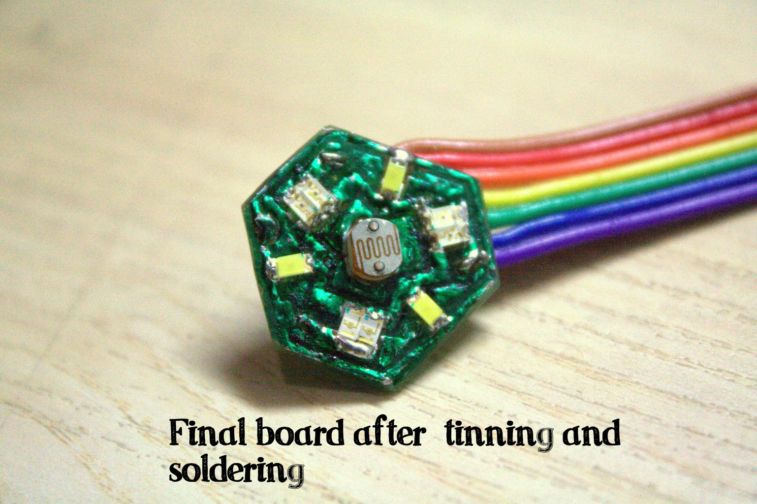


After the board is complete , Tin it using a chisel tip and solder.
Start soldering the LEDs first ( remember , the inner ring is for ground and the "blue" dot on the LED represents ground terminal ).
Then solder the SOT-23-3 BC847 transistors. Solder the 10K resistor and then solder the LDR.
Make sure that the LDR is firm and cap it with a 4mm heat shrink tube.
Now solder the ribbon cable ( in any sequence ). The other end of the ribbon cable has to be in a proper sequence
White - Red - Green - Blue - Vcc - Gnd - Analog
To make it look like "professional PCBs" paint it green / red using a permanent marker.
Your sensor is ready for testing !
Step 5: Testing and Graphing the Results


When you've finished making your sensors, plug them into your bread board and hook it up to your Arduino.
Arduino | Sensor
pin 9 -------R
pin 10 ------G
pin 11 ------B
Gnd -------Gnd
Vcc --------Vcc
A0 ---------Analog
Place a white object in front of the sensor and Run the given code on arduino :
int LED[3] = {9,10,11},i, j ;   // DECLARE  R   G   B  PINS

void setup()
{

  Serial.begin(9600);
  for(i=0;i<3;i++)                    // set LED pins to OUTPUT
  pinMode(LED[i], OUTPUT);
}

void loop()
{

  for(j = 0 ; j < 3 ; j++)                    //  CYCLE  PINS
  {
    for(i =0 ; i < 255 ; i++)                  //   CYCLE VALUES
    {

     analogWrite(LED[j],i);
     Serial.println(1024-analogRead(0));            //  PRINT  VALUES
     delay(100);
    }
analogWrite(LED[j],0);
delay(100);

}
}
And run this code in processing :
  import processing.serial.*;

 Serial myPort;                      // The serial port
 float xPos = 20,prevtime=0;         // horizontal position of the graph

 void setup () {
 // set the window size:
 size(1300, 700);

 // List all the available serial ports
 println(Serial.list());
 // I know that the first port in the serial list on my mac
 // is always my  Arduino, so I open Serial.list()[0].
 // Open whatever port is the one you're using.
 myPort = new Serial(this, Serial.list()[1], 9600);
 // don't generate a serialEvent() unless you get a newline character:
 myPort.bufferUntil('\n');
 // set inital background:
 background(255);
 }
 void draw () {
 // everything happens in the serialEvent()
 }

 void serialEvent (Serial myPort) {
 // get the ASCII string:
 String inString = myPort.readStringUntil('\n');

 if (inString != null) {
 // trim off any whitespace:
 inString = trim(inString);
 // convert to an int and map to the screen height:
 float inByte = float(inString);

 inByte = map(inByte, 0, 1023, 0, height);

 // draw the line:
 stroke(255,0,0);
 line(xPos, height, xPos, height - inByte);

 // at the edge of the screen, go back to the beginning:
 if(xPos>=width)
 {
   xPos=20;
   background(255);
 }
 else
xPos+=0.7;
 }
 }
Try changing the codes and delay values, the graphs will change
More delay gives more precise graphs
The graph clearly tells that the variation of brightness w.r.t the PWM values isn't same for R,G,B leds and hence they need to calibrated.
Step 6: Testing and Calibrating the Color Sensor

Now here comes the code , which analyses and calibrates each color as per the values that are reflected back.
/* Color Sensor code by - electro18
find more details about this project at : https://www.instructables.com/id/Your-Own-Color-Sensor-using-LEDs
This code is open source and is created by https://www.instructables.com/member/electro18/
It demonstrates the use of LEDs and LDRs as a color sensor

Steps:

Place a white screen in front of the sensor
Power up the arduino
Let it calibrate for a while
Once it is calibrated , the colors RGB will flash periodically
The percentage composition of the particular color will be displayed on the serial monitor
Open the serial monitor for debugging ang to verify the values

*/


int sensor,minVal, Val[3] , colArray[3] = {9,10,11},  total;

float Percent[3];

int i ,readRGB[3] , readMax[3], Domin;                  //  DECLARE VARIABLES

long calibtime,prevtime;                               //  RECORD THE TIME ELAPSED

void setup()
{

 Serial.begin(9600);

   for(i =0 ; i<3 ; i++)
    {
    pinMode(colArray[i],OUTPUT);                      // SET THE OUTPUT PINS
    }

    calibrate();                                      //  RUN THE CALIBRATE FUNCTION

}

void loop()
{

  total = 0 ;

   for( i = 0  ; i < 3 ; i++)                         //  CHECK VALUES IN A LOOP
  {
     prevtime = millis();
     while(millis()-prevtime < 1000)                      //  AVOID DELAY
     {
       analogWrite(colArray[i],Val[i]);                      //  WRITE THE CALIBRATED VALUES
       readRGB[i] = 1024 - analogRead(0);
       delay(50);
     }

  digitalWrite(colArray[i],0);

  prevtime = millis();                                         // RESET TIME

  total = total + readRGB[i];

  }


  for(i = 0 ; i < 3 ; i ++)
    {
	Percent[i] = readRGB[i]*100.0/total;                     //  PRINT IN THE FORM OF PERCENTAGE
        Serial.print(Percent[i]);
	Serial.print(" %   ");
    }

        Serial.println("");
        delay(1000);

}

/////////////////////////////////##############################################################################################////////////

  void calibrate()                                        //   CALIBRATE FUNCTION
  {

      for(i=0;i<3;i++)
      {
         while(millis()-calibtime < 1000)                    //    FLASH EACH COLOR AT MAX FOR 1 SEC
         {
             analogWrite(colArray[i],255);
             readMax[i] = 1024-analogRead(0);                       //    RECORD MAX VALUES
         }

   analogWrite(colArray[i],0);
   Serial.println(readMax[i]);
   delay(10);

   calibtime = millis();

 }

   if(readMax[0] < readMax[1] && readMax[0] < readMax[2])      //   GET THE MINIMUM VALUE FROM ARRAY

      minVal = readMax[0];

     else
     {

       if( readMax[1] < readMax[0] && readMax[1] < readMax[2])

       minVal = readMax[1];


      else

      minVal = readMax[2];

   }


    for(i = 0 ; i < 3 ; i++)
  {

       analogWrite(colArray[i],10);
       sensor = 1024 - analogRead(0);                                    // START CALIBRATION
       delay(100);

    while ( sensor - minVal <= -1 || sensor - minVal >= 1 )  //    GET THE DIFFERENCE BETWEEN CURRENT VALUE AND THRESHOLD
       {
         sensor = 1024 - analogRead(0);

         if( sensor > minVal )                                       //   INCREASE OR DECREASE THE VALUE TO EQUALIZE THE BRIGHTNESS
             Val[i]--;

             else
             Val[i]++;

             Serial.print(1024-analogRead(0));
             Serial.print("      ");
             Serial.println(minVal);

             delay(50);

             Val[i] = constrain(Val[i],0,255);                 //   CONSTRAIN THE VALUE B/W  0  -- 255
             analogWrite(colArray[i],Val[i]);
       }

 analogWrite(colArray[i],0);
 delay(50);

 }

  }
Working of the code :
STEPS :
1. Place a White non-glossy object in front of the sensor
2. Power-up your arduino
3. The sensor will start auto-calibration sequence
4. It will flash all three colors first , then it will equalize all the colors
5. The calibration process completes when it starts to cycle RGB sequence
6. Place any object whose color you want to analyze
7. Open the serial monitor for getting the values in % format
Explanation :
Basically the sensor Flashes each color and records the max values when a white object is placed in front of it.
It notes the light that reflects back and compares all the values.
The minimum value is set as the threshold and then it tries to equalize all the colors ( R, G, B )
After the calibration has been done , the program starts the loop which checks the color. It does the job by reading the reflected colors from the surface and then converting these values in a systematic form.
The amount of color reflected tells the percentage of every color in the particular color.
Step 7: Applications
Recently, I've used this sensor to make a Chameleon lamp.
This lamp uses a color sensor to sense the color of it's base and replicate it using RGB LEDs. It is interesting to see how simple and cheap electronics can be used to make something unusual. And the lamp worked quite well ( unexpectedly though :D )
Still there are infinite possible ways in which this sensor can be used.
Step 8: TROUBLESHOOTING AND CONCLUSION
Troubleshooting and Precautions :
1. Verify that the LEDs are flashing correctly
2. Ambient light may interfere with the sensor and give false readings
3. To calibrate the sensor , you need a perfectly white and non-glossy surface.
4. Use appropriate current limiting resistors for your LED
Conclusion :
This project is an example of how some simple components can be connected together to form something unique and fascinating.
This sensor can be used in robots, for sorting objects of different colors and so on....
Questions , suggestions and critics are welcome :)
If you find my Instructable interesting then please leave a vote :)

Second Prize in the
Tech Contest

Participated in the
Formlabs Contest

Participated in the
Remix Contest

Participated in the
Microcontroller Contest


