Introduction: 3D Printed Microcontroller Dice Roller
This is a just-for-fun project I did in the Digilent MakerSpace. Usually whenever I play board games I use a dice-rolling smartphone app since dice are so easy to lose. I thought I would try making my own hardware version though. It turned out really well and was a lot of fun. In this Instructable I will go over how I designed the circuitry, wrote the code for the microcontroller, made the housing, and put it all together!
I entered this project in several contests on Instructables. If you like this project, please vote for it by clicking the "Vote!" ribbon in the top right corner.
Step 1: Materials
Here's a list of the parts I used for this project.
- chipKIT uC32 Microcontroller and USB cable
- You can also use a lot of other microcontrollers such as the Arduino Uno, or chipKIT Uno32
- 7 green 5mm LEDs
- Push button (approx. 6mm wide)
- 2 zUNO clips to hold the microcontroller board
- You can order some or even 3D print your own zUNO clips for free at the link above.
- 3D printed housing (file below)
- Not everyone has access to a 3D printer, but there are plenty of other options here. A thick card stock or paperboard will work perfectly. Also, if you want a 3D printed version and don't have access to a printer, there are several companies (such as i.materialise, Sculpteo, Ponoko, and Shapeways) that will print a design for you and mail it to you.
- For putting everything together you just need some basic tools: wire cutters, a soldering iron, and some glue (hot glue and super glue both work well).
My 3D print design can be found at this link. From this page you can order a print from one of the companies I mentioned above. Or, if you will be printing it yourself, you can download the file here too. Tinkercad will also allow you to make a copy of the file so you can make your own edits. You can make changes to the design to use a different size of LEDs or a different button. You can also make it bigger and even add text or logos!
Now onto the design. I will start by explaining the circuitry in the next step. After that, I will talk about programming the microcontroller. And last but not least, putting it all together!
Note: If you are going to be printing the housing, I would start that now as you continue through the remaining steps. Then the print will be done when you're ready to put everything together.
Step 2: The Circuit
The circuit for this project is very simple. We just need a power and ground connection to the LEDs and a few wires going to the button. Note: the "power" to the LEDs comes from the microcontroller's Digital I/O pins.
I included a schematic view of the uC32 so you can see how everything will eventually be connected to the board.
Step 3: Programming the Microcontroller
I wrote my code in MPIDE. MPIDE is completely free and can be downloaded here. Note: MPIDE can program just about any microcontroller, including all chipKIT and Arduino boards. If you're using an Arduino board and already have Arduino's IDE that will work just as well too.
If you're brand new to microcontrollers and programming in an IDE, here is a quick tutorial that explains how to install MPIDE and use it to communicate with your board: Intro to MPIDE.
The code I wrote for the microcontroller can be seen below. There are three main portions to this "sketch":
- The roll() function which makes it look as if the die is actually rolling. This is a function I created myself and it is included in the code below.
- Generating a random number between 1 and 6 with the rand() function. (This function is predefined in the stdlib.h header file.)
- And a series of if statements to light up the correct LEDs based on the random value that is generated.
This code can be copied directly from the box below and pasted into your IDE. Then you can upload it directly to your board from there. If you're unsure how to upload the sketch, check out the "Intro to MPIDE" tutorial linked above.
Note: Sorry for the very space-consuming formatting for the code. It used to display in a nice little box that you could scroll through, but Instructables made some changes to their editing interface and I'm not able to do that anymore.
#include // to use the rand() function
// Initializing the pin used for button input
const int btnPin = 26;
// Initializing pins to control each LED
const int led_left_top = 33; // LED in top left corner of die
const int led_left_center = 32; // LED in on the left side of the die in the center row
const int led_left_bottom = 31; // LED in the bottom left corner of the die
const int led_right_top = 30; // LED in the top right corner of the die
const int led_right_center = 29; // LED on the right side of the die in the center row
const int led_right_bottom = 28; // LED in the bottom right corner of the die
const int led_center = 27; // LED in the center of the die
// Creating a function to simulate the action of a die rolling
// Function will make LEDs flicker through numbers 1-6
void roll()
{
int i = 0; // Counting variable for loop
for (i = 0; i < 5; i++) // cycle 5 times
{
// Display 1
digitalWrite(led_left_top, LOW);
digitalWrite(led_left_center, LOW);
digitalWrite(led_left_bottom, LOW);
digitalWrite(led_right_top, LOW);
digitalWrite(led_right_center, LOW);
digitalWrite(led_right_bottom, LOW);
digitalWrite(led_center, HIGH);
delay(50); //wait 50ms before displaying next value
// Display 2
digitalWrite(led_left_top, HIGH);
digitalWrite(led_left_center, LOW);
digitalWrite(led_left_bottom, LOW);
digitalWrite(led_right_top, LOW);
digitalWrite(led_right_center, LOW);
digitalWrite(led_right_bottom, HIGH);
digitalWrite(led_center, LOW);
delay(50);
// Display 3
digitalWrite(led_left_top, HIGH);
digitalWrite(led_left_center, LOW);
digitalWrite(led_left_bottom, LOW);
digitalWrite(led_right_top, LOW);
digitalWrite(led_right_center, LOW);
digitalWrite(led_right_bottom, HIGH);
digitalWrite(led_center, HIGH);
delay(50);
// Display 4
digitalWrite(led_left_top, HIGH);
digitalWrite(led_left_center, LOW);
digitalWrite(led_left_bottom, HIGH);
digitalWrite(led_right_top, HIGH);
digitalWrite(led_right_center, LOW);
digitalWrite(led_right_bottom, HIGH);
digitalWrite(led_center, LOW);
delay(50);
// Display 5
digitalWrite(led_left_top, HIGH);
digitalWrite(led_left_center, LOW);
digitalWrite(led_left_bottom, HIGH);
digitalWrite(led_right_top, HIGH);
digitalWrite(led_right_center, LOW);
digitalWrite(led_right_bottom, HIGH);
digitalWrite(led_center, HIGH);
delay(50);
// Display 6
digitalWrite(led_left_top, HIGH);
digitalWrite(led_left_center, HIGH);
digitalWrite(led_left_bottom, HIGH);
digitalWrite(led_right_top, HIGH);
digitalWrite(led_right_center, HIGH);
digitalWrite(led_right_bottom, HIGH);
digitalWrite(led_center, LOW);
delay(50);
}
} // End of roll function
// Initiliazing variable to represent die value
int die_value = 0;
voidsetup () // configure microcontroller pins
{
//Set button pin for input
pinMode(btnPin, INPUT);
// Set LED pins to output
pinMode(led_left_top, OUTPUT);
pinMode(led_left_center, OUTPUT);
pinMode(led_left_bottom, OUTPUT);
pinMode(led_right_top, OUTPUT);
pinMode(led_right_center, OUTPUT);
pinMode(led_right_bottom, OUTPUT);
pinMode(led_center, OUTPUT);
}
voidloop ()
{
// Check for button press
if (digitalRead(btnPin) == HIGH) // if button was pressed
{
roll(); // Simulate die roll
die_value = (rand() % 6) + 1; // Randomly select die value, this code will generate a number between 1 and 6
if (die_value == 1) // only center LED is lit
{
digitalWrite(led_left_top, LOW);
digitalWrite(led_left_center, LOW);
digitalWrite(led_left_bottom, LOW);
digitalWrite(led_right_top, LOW);
digitalWrite(led_right_center, LOW);
digitalWrite(led_right_bottom, LOW);
digitalWrite(led_center, HIGH);
}
elseif (die_value == 2) // only the top left and bottom right LEDs are lit
{
digitalWrite(led_left_top, HIGH);
digitalWrite(led_left_center, LOW);
digitalWrite(led_left_bottom, LOW);
digitalWrite(led_right_top, LOW);
digitalWrite(led_right_center, LOW);
digitalWrite(led_right_bottom, HIGH);
digitalWrite(led_center, LOW);
}
elseif (die_value == 3) // the top left, bottom right, and center LEDs are lit
{
digitalWrite(led_left_top, HIGH);
digitalWrite(led_left_center, LOW);
digitalWrite(led_left_bottom, LOW);
digitalWrite(led_right_top, LOW);
digitalWrite(led_right_center, LOW);
digitalWrite(led_right_bottom, HIGH);
digitalWrite(led_center, HIGH);
}
elseif (die_value == 4) // the four LEDs on the corners are lit
{
digitalWrite(led_left_top, HIGH);
digitalWrite(led_left_center, LOW);
digitalWrite(led_left_bottom, HIGH);
digitalWrite(led_right_top, HIGH);
digitalWrite(led_right_center, LOW);
digitalWrite(led_right_bottom, HIGH);
digitalWrite(led_center, LOW);
}
elseif (die_value == 5) // the 4 corner LEDs and the center LED are lit
{
digitalWrite(led_left_top, HIGH);
digitalWrite(led_left_center, LOW);
digitalWrite(led_left_bottom, HIGH);
digitalWrite(led_right_top, HIGH);
digitalWrite(led_right_center, LOW);
digitalWrite(led_right_bottom, HIGH);
digitalWrite(led_center, HIGH);
}
else// die_value == 6 and all LEDs are lit except the center one
{
digitalWrite(led_left_top, HIGH);
digitalWrite(led_left_center, HIGH);
digitalWrite(led_left_bottom, HIGH);
digitalWrite(led_right_top, HIGH);
digitalWrite(led_right_center, HIGH);
digitalWrite(led_right_bottom, HIGH);
digitalWrite(led_center, LOW);
}
delay(4000); // displays die value for 4000ms, or 4 seconds
}
else// LEDs stay off if button has not been pressed
{
digitalWrite(led_left_top, LOW);
digitalWrite(led_left_center, LOW);
digitalWrite(led_left_bottom, LOW);
digitalWrite(led_right_top, LOW);
digitalWrite(led_right_center, LOW);
digitalWrite(led_right_bottom, LOW);
digitalWrite(led_center, LOW);
}
}
Step 4: Putting It All Together
This is the part that I think is the most fun! For one, I love soldering. And it's really awesome getting to see the design come together.
Here's a brief summary of what we need to do:
- Place the LEDs in the top piece of the housing.
- Solder all the connections to the LEDs.
- Place the button in the square hole of the front panel of the housing.
- Solder the button connections.
- Attach the zUNO clips to the base of the housing.
- Assemble the cube and attach it to the base.
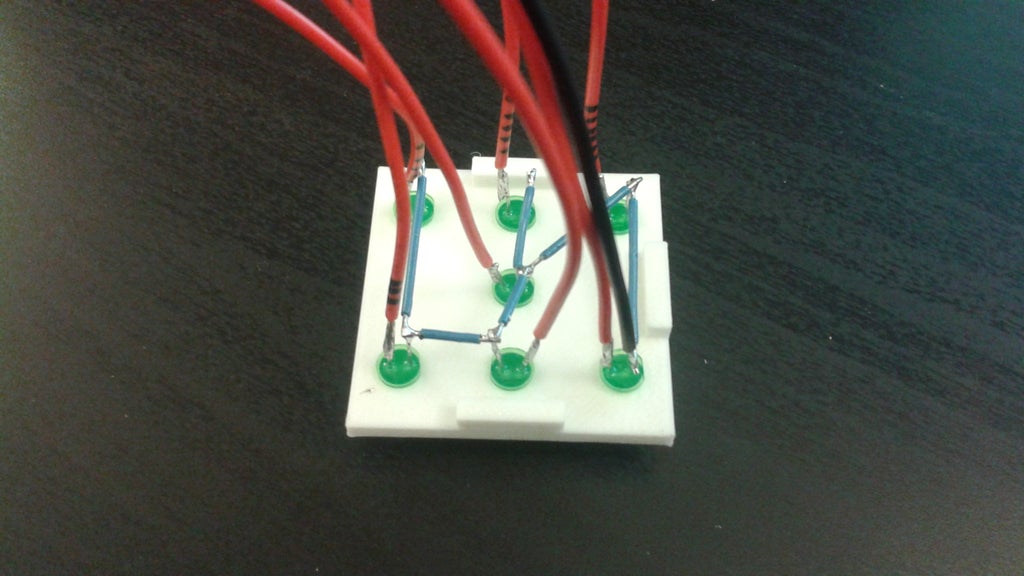
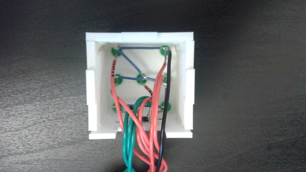
I started by placing all of the LEDs and soldering their connections. For the housing I printed, the LEDs fit perfectly in the holes such that they stayed tightly in place without any glue. Depending on your printer you may need a little bit of glue to help them stay in place.
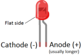
For soldering the LEDs, it is very importantthat the LEDs are connected with the correct orientation. The anodes of the LEDs will be connected to the digital I/O pins of the microcontroller, and the cathodes of the LEDs will be connected to Ground.
As you can see in my picture, I connected all of the cathodes together with blue wires. Ground connections do not have to be specific, so we can connect all of the cathodes together and then connect that group to ground with a single wire (the black one in the image). This makes it a lot simpler then having seven separate ground wires. After connecting all the cathodes together and to a single ground wire, I connected a separate wire to each of the anodes of the different LEDs. These are the red wires in the picture. As you can see, I used a marker to put some tally marks on each one. This makes it easier to keep track of which wire will be connected to each pin of the microcontroller.
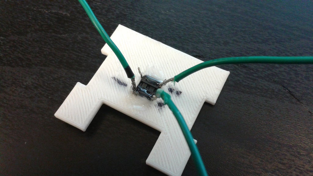
Next, I put the button in the square hole of the front panel. This required a little bit of hot glue on the back to hold it in place. The picture above doesn't show my nicest looking work, but when we put the cube together this side won't be seen.
Recall from the schematic that only 3 of the 4 pins on the button are connected. One is connected to ground through a 220Ω resistor. Another pin is connected to the microcontroller's 5V power source. The other pin is connected to pin 26 of the microcontroller. Pin 26 reads whether the button has been pressed or not. You can see how I soldered the wires in the picture above. Notice that I labeled the wires with one dot, two dots, and a dash. This is to keep track of what wire goes to which pin on the microcontroller. One dot is for the wire that goes to pin 26. Two dots is for the wire that connects to the microcontroller's 5V supply. The dash is for the wire that connects to the microcontroller's GND.

For the 220Ω resistor at the ground connection, I just put one end of a resistor into the end of my connector. The exposed pin of the 220Ω resistor will be connected directly to the GND pin of the microcontroller. If you aren't using MTE cables like I am, you can just solder a resistor to the other end of your wire.
The next step is to attach the zUNO clips to the base. The holes on the zUNO clips were a little too big for the pins on the base, but a little bit of hot glue over the joint makes it fit well and stay in place. 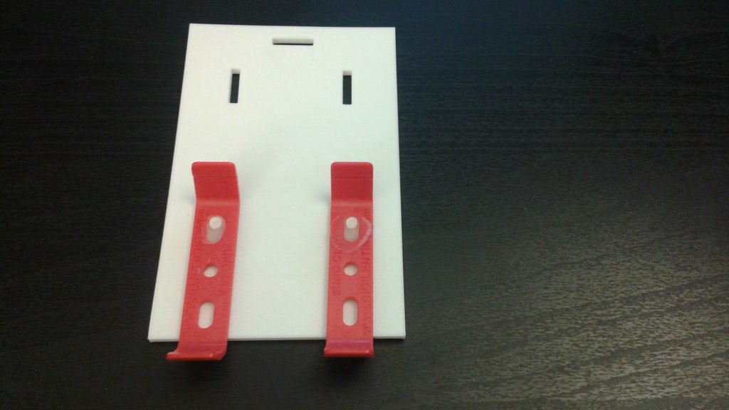
Now let's put the whole cube together. Use glue as necessary to hold the sides of the cube together. Also try to keep the wires lined up nicely so they will all be coming out of the front panel when we place the cube on the base.
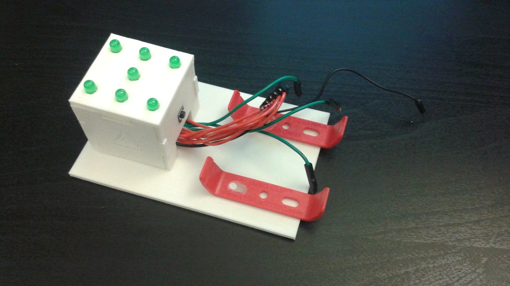
All that's left now is to put the cube on the base! I didn't need any glue to hold the cube in place because the cube fit into the holes of the base perfectly. But use glue as needed to keep the cube attached. The final result is shown below! Move on to the next step to see it in action.
Step 5: The Final Result!
Lastly, mount the microcontroller onto the zUNO clips and plug in all the wires.
The pin numbers that each wire needs to connect to is shown in the code in step 3, but to review:
- The LEDs are connected to pins 27-33.
- The ground wire of the LEDs is connected to the microcontroller's GND.
- The wire that carries the button's state (whether it's been pressed or not) is connected to pin 26.
- Another wire of the button is connected to the microcontroller's 5V supply, and the button's last wire is connected to the microcontroller's GND through a 220Ω resistor..
Then just upload the sketch from the IDE to your microcontroller and it's ready to go! Check it out in the video above!
Please don't hesitate to ask any questions if you have any!
Also, as I mentioned, I entered this project in several contests on Instructables. So if you like this it, please consider voting for it by clicking the "Vote!" ribbon in the top right corner.


