

Introduction: AirCasting LiteBeam


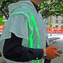

Staring at a screen can be a drag (and may lead to being run over while
walking or biking!) so we developed the LiteBeam to communicate the AirBeam measurements using LEDs. The LiteBeam uses a IOIO microcontroller connected to the AirCasting app over Bluetooth to illuminate LEDs in response to the sensor measurements received by the AirCasting app: green for low intensity, then yellow, then orange, and red for high intensity.
Step 1: LiteBeam Schematic & Parts


Links to parts are provided for convenience only; they are not an endorsement of the vendor. Most of these parts are available from multiple vendors. Note that not all Bluetooth dongles are compatible with the IOIO.
LiteBeam Parts
Step 2: Wiring the SPDT Switch


Bend one of the outside legs on the SPDT switch. The bent leg will not be used. Grab two black jumper cables and one white. Using a pliers, hook the ends before soldering as shown.
Step 3: Wiring the RGB LED

Grab one black jumper cable, one green, and one red. Apply solder to the green (G), red (R), and ground (-) metal plates on the RGB LED. Then solder the jumper cables as shown.
Step 4: Wiring the IOIO

Grab two red jumper cables, one black, and one green. Insert the red jumper cable into pin 35 of the IOIO, hook the end using a pliers, and solder in place. Insert the green jumper cable into pin 36, hook the end using a pliers, and solder in place. Insert the black jumper cable into the center pin of the ground (GND) row, hook the end using a pliers, and solder in place. Insert the second red jumper cable into the middle pin of the 5V row, hook the end using a pliers, and solder in place.
Step 5: Wiring the Transistors to the Breadboard

Grab two transistors and the breadboard. Rotate the transistors until the small metal tab is on the lower left. Leaving one row to the right, insert the legs of the transistors into the board as shown. Flip the board over and bend the legs until they are flush with the board as shown. Then insert a yellow jumper cable on the upper left side of the transistor as shown. Then flip the board over and solder the yellow jumper cable to the upper legs of the transistors.
Step 6: Wiring the Li-Po Charger

Grab the switch, the breadboard, and the Li-Po charger. Insert one of the black cables running from the switch into the breadboard, bend the leg so it's flush with the board and solder it. Insert the other black cable running from the switch to the ground (GND) on the Li-Po charger. Bend the leg so it's flush with the board and solder it. Insert the white cable running from the switch to the enable (EN) pin on the Li-Po charger. Bend the leg so it's flush with the board and solder it. Insert a red jumper cable into the 5 volts (VCC) pin on the Li-Po charger. Bend the leg so it's flush with the board and solder it. Insert the other end of the red cable into the breadboard pin closest to the yellow jumper cable. This is the yellow cable that is next to the transistor that is closest to the edge of the board. Bend the leg so it's flush with the board and solder it to the yellow cable and the transistor.
Step 7: Connecting the RGB LED

Insert the black cable running from the LED into the breadboard pin next to the black cable running from the switch. Bend the leg so it's flush with the board and solder it to the other black cable. Insert the green cable running from the LED into the breadboard next to the transistor that is closest to the edge of the board. Be sure to insert it through the breadboard pin next to the transistors metal tab. Then bend the leg so it's flush with the board and solder it to the leg of the transistor. Insert the red cable running from the LED into the breadboard next to the other transistor. Be sure to insert it through the breadboard pin next to the transistors metal tab. Then bend the leg so it's flush with the board and solder it to the leg of the transistor.
Step 8: Connecting the IOIO to the Breadboard


Insert the red jumper cable running from pin 35 of the IOIO into the breadboard to the right of the transistor, as shown. Then bend the leg so it's flush with the board and solder it to the leg of the transistor. Insert the green cable running from the IOIO into the breadboard to the right of the transistor, as shown. Then bend the leg so it's flush with the board and solder it to the leg of the transistor. Insert the black cable running from the IOIO into the breadboard hole nearest the other two black cables. Then bend the leg so it's flush with the board and solder it to the other two black cables. Insert the red cable running from the IOIO into the breadboards upper left corner, as shown. Then bend the leg so it's flush with the board and solder it to its neighbors (red, yellow, and leg).
Step 9: Connect the Battery and BT Dongle

Connect the battery to the Li-Po charger. Connect the USB adapter to the IOIO. Connect the Bluetooth dongle to the USB adapter.
Step 10: Insert the RGB LED Into the Enclosure

Slot the LED into the tabs on the enclosure and hot glue gun into place.
Step 11: Insert the IOIO Into the Enclosure

Insert the IOIO as shown
Step 12: Insert the Battery & Switch

Insert the battery as shown. Insert the switch as shown and hot glue gun into place.
Step 13: Insert the Li-po Charger & Breadboard

Insert the Li-Po charger and breadboard as shown. Screw the enclosure together using a Torx screwdriver size "18". Note that it takes a lot of fiddling to fit all the electronics inside the enclosure.
Step 14: Connect Your LiteBeam to the AirCasting App

Download the AirCasting app from the Google Play Store. Navigate: menu button > "Settings" > "External devices" > "Pair with new devices" > search for "Available devices" > select the IOIO > enter the pairing code "4545" > press the return button > press "IOIO". The AirCasting app should navigate to the "Sensors Dashboard" and your LiteBeam should light up! Note that you only need to pair the IOIO once. After that you can skip pairing and just connect.


