

Introduction: Bench-mounted Router Table


Ask any bunch of woodworkers which is their most essential fixed power tool and you'll get many answers. But ask for the top three, and they will always include the router table.
In recent years, router manufacturers have begun offering routers with height adjustments that can be accessed through the base, when the router is hanging upside down in a router table. This eliminates the cost and complexity of incorporating a router lift into the design to control the height of the bit. These new routers have that built-in.
Inspired by these, a number of writers have published designs for router tables using these new routers that aren't really tables, they're router table tops, meant to be attached to an existing workbench.
Bench-Mounted Router Table
Stow-and-Go Router Table
Stow-Away Router Table
When I was building my own Real Woodworker's Workbench, I had to buy a second router. I decided to buy one with an integrated lift, and to use it to build a router-table attachment for my bench, similar to those described above.
It took me longer to get around to it than I had planned, but a few weeks ago I finally got started.
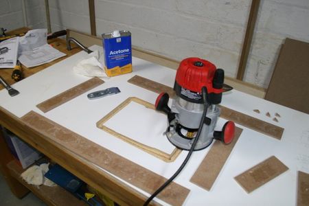
I made it out of a 24"x48" piece of 3/4' Melamine-coated particle board, with a 3/4' backing of Medium Density Fiberboard (MDF), using a commercially purchased insert plate and fence. Melamine provides a slick, smooth, easily-cleaned surface, which makes it a pretty good choice for a top. 3/4' isn't enough to prevent bending, though, and the fiberboard core isn't as dense as MDF, hence the MDF backing.
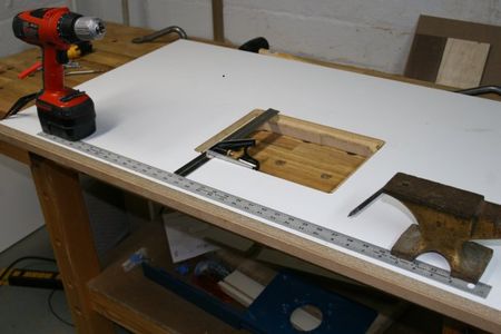
Step 1: Laying Out the Mortise


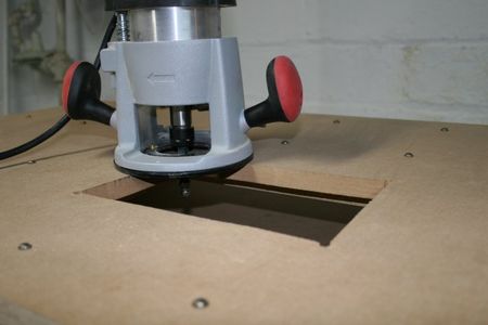
The router, in a router table, is screwed to a router table insert plate. The insert plate is a flat piece of stable material (often metal, sometimes acrylic or wood), that sits into a reset mortised into the top. The first task in building the table is to cut out this mortise. This is usually done with a hand-held router.
I bought a commercial plate, and the manufacturer offered a template sized to match the plate. I didn't buy one. It required a 1/2" pattern cutting bit, which I didn't have, and didn't have any other immediate need for. So instead of shelling out $30 for the template and bit, I made up a template of my own that I could use with a guide bushing kit and the bits that I already had.
A guide bushing is used with a straight bit. It rides along the side of the template, keeping the bit a set distance away from the template. The critical factor is the distance between the outside of the bushing and the edge of the bit.
I constructed my template out of straight strips of 1/4" MDF, held in place with double-sided carpet tape. As I said, the critical dimension is the offset, the distance between the outside of the bushing and the outside of the bit. This equals the radius of the bushing minus the radius of the bit, or half of the difference between the diameter of the bushing and the diameter of the bit.
Fasten the insert plate to the top, in the position you want it to be, with double-sided tape. Tape straight strips of 1/4" MDF around the plate, separated from it by your calculated distance. Peel up the insert plate, and then tape down some pieces of 1/4" MDF in the center, to help provide stability for the router. The position of these inside pieces isn't critical, so long as the gap between them and the outside pieces is wide enough that you can route an area greater than the width of the lip you want to end up with.
I added some small triangular pieces into the corners, to keep the bit from cutting too sharp a radius.
Step 2: Cutting the Mortise


Once the template has been built up, it should be routed out. This should be done in two passes, once taking a shallow cut, then a second pass at full depth.
Once the mortise has been routed out, remove the center section by drilling a hole in each corner and joining them with a jigsaw. The resulting mortise can then be tested for width and length.
The next step is to peel up all the pieces that had made up the template, both on the table and in the center rectangle that you've cut out. You'll want the router base to move easily across them, so make sure you remove all the tape residue. (I found that acetone and a razor blade made it a reasonably easy job).
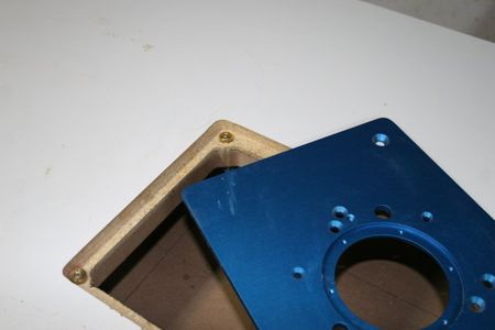
Remove the guide bushing and the bit you've been using with it, and switch to a straight bit that has the same radius as the insert plate. Position the pieces of template to guide along the side of the router, preventing it from cutting farther into the table top, and then take another pass with the router, cleaning up the bottom of the cut, and making properly-rounded corners. Once done, the plate should fit neatly into the hole.
I made one more pass, with the guides set 5/8" closer to the mortise, and the bit set deeper, to make a cleaner edge on the lip than had been left by the jigsaw. This isn't necessary, but it's little work.
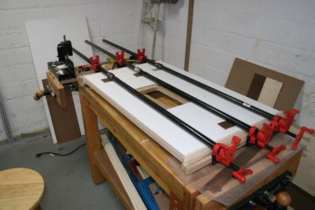
Step 3: Laminating the Top


A single piece of 3/4" Melamine is rather thin, for a router table top, particularly when it is intended to be used only partially supported by a workbench. You can't make consistent cuts if your table is flexing while you work, so I decided to back my Melamine top with a layer of 3/4" MDF.
The trick to successfully laminating sheet goods is constant, even pressure. There are folks who have vacuum presses designed explicitly for this job. I don't have one. Instead, I use screws, in a regular grid about 6" across. The holes through the MDF should have a diameter sufficient that the threads don't engage in the MDF. We want to pull the MDF and the Melamine together.
I marked the MDF, drilled holes through the MDF, and cleaned up the tearout from the drill with a block plane. Then I set the MDF on the Melamine and used an awl and a mallet to mark the positions of the holes. I then drilled pilot holes into the Melamine at the marked spots.
The glue-up is simple, provided you make sure you have everything on-hand before you start. You've only a limited amount of time once you set the pieces together before the glue bonds. That's not the time to realize you need to run out to the garage because you don't have your screwdriver or clamps.
Spread a thin layer on each surface (bottom of the top and top of the bottom). Flip the MDF on top of the Melamine, line up the holes, and insert some screws into opposite corners. Don't tighten them all the way down, leave some slack. I found that lifting the top layer up a couple of inches, then running an awl through the hole, made it easy to get the holes lined up.
Once you have the opposite corners screwed together, clamp both pieces down to your work top. If your top is flat, this will force the MDF and the Melamine to be flat, while the glue cures. (Nether MDF nor Melamine is as stiff as it appears to be. Both will easily take on subtle curves that will give you no end of headaches, if you allow them to survive to your final product.
With the corners clamped, tighten up all the screws, and let the assembly sit overnight. After the glue has set, remove the screws.
Step 4: Inserting the Leveling Screws


Once the Melamine has been laminated to the MDF, the next step is to cut out the mortise in the MDF. This is done in the usual way - drill holes through the corners, join with a jigsaw, then use the router with a flush trim bit to route it to match the mortise in the Melamine.
A warning - MDF dust is toxic, and routing creates a lot of it. Use a mask, and whatever dust collection you have. Even something as simple as a furnace filter and a fan can catch a lot of the fine stuff that would otherwise hang around in the air for hours.
With the mortise done, the next step is to add leveling screws. What hardware you use for this depends upon what you have available. I didn't want to thread the screws straight through the MDF - I didn't think it would hold a thread. But there wasn't enough room on the lip for most of the tee-nut designs I'd seen. So I went down to the hardware store and looked at what they had.
What they had included some simple knurled nuts that looked like they could easily be adapted to my needs.
The result was simple - a knurled nut press-fit into each corner, with a thumbscrew running through it so I could adjust the height. A simple hex nut on each thumbscrew provided for a way to tighten things down.
I drilled a hole just large enough in diameter to pass a thumbscrew in each corner, then drilled a larger countersink that was just a bit smaller in diameter than the knurled nut. I then threaded them through the holes and used a wrench to force the knurled nut into the hole.
The result was a leveling screw in each corner that could be used to adjust the height of the insert plate to exactly match the top.
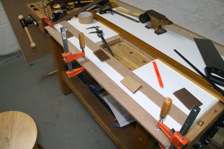
At this point, I had a router table. It didn't have a fence, and it didn't have a miter slot, but it was a flat top from which I could hang a router, if I'd needed to use it. Still, I wanted a fence, and I wanted a miter slot, and I wanted to band the whole thing with hardwood, to keep the edges of the Melamine from chipping. (You can see from some of the pictures that the Melamine has already chipped along some edges, simply from its handling at the Home Store). And I wanted to add some more support, under the part of the top that would not be supported by the bench, though I'm not really certain that it is necessary.
Step 5: Trim to Size


The next step is to trim to size. Before we can do that, we need to decide upon the size. The width is simple. The wider, the more support the bench can provide. Length needs more consideration. How long is the material? How long is the fence? If you're inlaying a purchased miter track, how long is that? And where are you going to store it?
I wanted mine to fit on the shelf under my bench, so I decided on 40", because the distance between the legs is 41". I intended to wrap it with 1/2" hardwood, so I cut it to 39".
Parallelism isn't really much of an issue in a router table, because the cutting tool is a fixed point. In a table saw, it is essential that the miter track be parallel to the blade. On a router table, such parallelism is only a cosmetic issue. Still, for the plate to be noticeably not parallel to the edge, or for the edges to be noticeably not square would make it look rather odd, so I made an effort to maintain parallelism and perpendicularity.
I marked off a line parallel to the edge of the mortise, and extended it to the bottom. I then made a straight cut across the bottom between the marks. I made all the cuts with the Melamine on the bottom. The blade on a circular saw cuts up, towards the saw, so tear-out occurs on the top side. (A table saw cuts down towards the table, so tear-out occurs on the bottom side).
I used a drywall square to layout perpendicular cuts for the other three sides. The cuts, themselves, I made with a circular saw and the cutting guides I made while making my workbench.
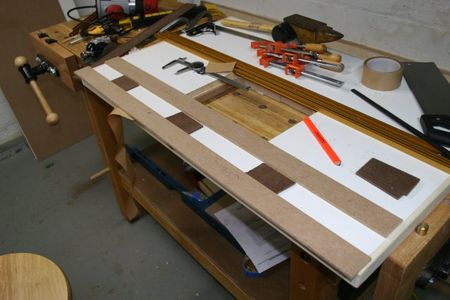
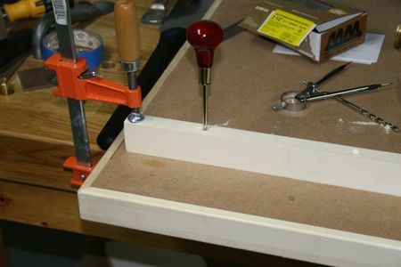
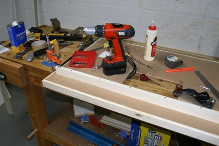
Step 6: Edge-banding the Top


Because Melamine chips easily, along the edge, I decided to edge-band the top with hardwood. This is just a shop tool, not a piece of fine furniture, so there's no real need to use miter corners, instead of plain old butt joints, but I did, anyway.
You want four pieces, each at least half-an-inch wider than the top is thick, two at least two inches longer than the top is wide, and two at least two inches longer than the top is long.
I had a plank of 1/2"x6" aspen on the shelf, which would serve the purpose. First I cut it in two pieces of the appropriate length, and then ripped each into pieces pieces of the appropriate width.
I still don't have a table saw, and setting up a jig for rip cutting narrow boards on a circular saw seemed more work than was necessary, for so few cuts, so I just clamped the boards to the edge of the bench with my holdfasts and cut it with a handsaw. A problem immediately arose - the saw I should have been using was out in the garage, and I didn't feel like going out to get it. So I used a flush-cutting pull-saw, which served, but needed some care. The biggest problem was that because I was pulling away from the bench, instead of pushing into it, and because I was cutting such narrow stock, I had to reposition the holdfasts as I cut. If the area where I was cutting was more than six or eight inches away from a holdfast, the pull would flex the board, rather than cut. Fortunately, re-positioning holdfasts is fast and easy.
The trick to getting good miter joints is to assume that all of your measuring tools are lying to you. Start by figuring out how to get a real 45-degree cut with whatever tool you are using. I'll guarantee you one thing, whatever tool you use, be it miter box, miter saw, table saw, or whatever, if it has an mark for a 45-degree angle, it's going to be wrong. Cut a couple of pieces of scrap at opposing 45-degree angles, and match them up against something you know is square. Then figure out what you need to do to get a real 45-degree cut, instead of the 42-degree cut your tool actually delivers when you set it to 45.
When you know you are cutting at the right angle, make a 45-degree cut on one end of each piece. The other ends we'll mark and cut - and perhaps trim just a bit with a hand plane or a sanding block - by fitting them in place, not by measuring. Measuring is a source of inaccuracy.
Set the top up on some scrap, so that it's not resting directly on your bench. You want the edge banding strips to extend just a bit above and below the edge of the top, so you need a bit of a gap. Take one of the short strips and one of the long strips, and match them up at to form a proper miter joint at one corner of the top, extending along the appropriate sides. Clamp or tape them into place. Then go to the other end of each piece, and mark the angle you need to saw. Do the same with the other two pieces, along the other two sides of the top. Mark the strips against the specific sides that they will be glued to, in the orientation that they will be glued. You can number the sides and the top with a pencil, to help you keep track.
Take your strips back to the miter box (or whatever you are using), and cut just a little bit past the mark, leaving each strip perhaps 1/16" longer than you need. Fit the pieces back together, around the top, and them trim the last little bit on each to make them fit together properly. (A jack plane and a shooting board would be the best tool for this, but I'm still refurbishing my jack plane, and I've not yet built a shooting board, so I just used a sanding block).
Once all of the strips fit, glue them up, two at a time. Spread glue on two opposing edges, spread glue on their matching strips, and clamp them in position, with cawls to spread the pressure. When the glue is dry, route the edges flush with the top. Then glue on the other two strips, and then route them flush. Finally, grab a round-over bit and round off the corners.
Step 7: Miter Track and T-track


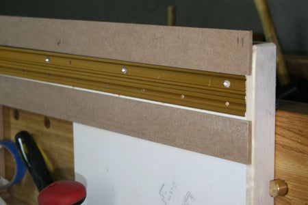


The commercial fence I'd bought needs a pair of tracks along which to adjust. I decided to use t-track for this, because I was uncertain of how well a simple routed track would hold up. Miter tables don't always include miter tracks, but they often do. If for nothing else than for holding feather boards. I was torn, though, between miter track and t-track in the miter track position. I ended up putting in both.
I used the guide bushing and bit that I had for routing the mortise for the insert plate, and the same technique of building up a template out of strips of 1/4" plywood.
I set the template just slightly narrow, figuring it would be easier to widen the groove than to make it narrower.
I routed in several passes. First, cutting just deep enough to remove the plastic, with the idea that this would reduce tear-out. Then about half my intended depth, then just shy of my intended depth, and then, after checking the fit of the track to the full depth. Then I cleaned up any remaining high spots with a chisel.
I left a half-inch or so on each end unrouted, because I feared tear-out. I cleaned it up with a flush-cut saw and a chisel.
Step 8: Stretchers


The back third of the top will be supported by the workbench, the rest will hanging off the side. This section could use some additional support.
Step 9: A Minor Fix


When I first mounted my router to the insert plate, and tested it against the top, I found a problem. There router has a knob that is used to lock the spindle from spinning, while you use a wrench on the collet. This knob wouldn't turn, because it ran into the MDF.
It only took a moment to route out enough to make it work.
Step 10: Bolting It to the Top


I could have used 3/4" dowels and some long bolts, but that would mean having to reach under the bench to tighten things down. instead, I went with Veritas Bench Anchors.
I drilled a 3//8" hole in the end of a piece of 3/4" dowel, and inserted a 3/8" dowel center.
Then I put the router table in position. "In position" means that the short stretchers are bumped up against the side of the bench. Then I held it there with a couple of holdfasts. I used the dowel+dowel center to scribe the positions of the two benchdog holes I intended to use to hold the top down, then flipped the top upside down.
I used a drill guide to drill at the marked locations. These are holes that need to be precisely placed, and precisely vertical.
Step 11: Finished


The final step is to set the top on the bench, line up the holes, screw in the bolts, fasten the router to the insert plate, drop the plate in the mortise, and start routing.


