

Introduction: Bluetooth Speaker W/ Music-Reactive LED Matrix


This project is entered in the Wireless Contest and the LED Contest -- if you like it, I would greatly appreciate your vote. Thanks!
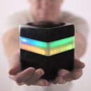
I designed and built a DIY Bluetooth Speaker with an integrated LED matrix. The LED matrix includes a number of different visualization modes, including a fireplace mode, an abstract “moving art” mode, and several that react to the music via a microphone inside of the speaker box. I haven’t seen any other product designed for the home, which marries sight and sound in this way.
The idea for this project came about in a somewhat unorthodox way. I wanted to build something for several friends expecting newborns. I wanted a gift that would help their children develop neurologically, and a gift that they wouldn’t outgrow. Having done a number of LED projects, and having some woodworking experience, I came up with the idea to integrate an audio-reactive LED matrix in a Bluetooth speaker.
The speaker box involved a fair amount of woodworking. The outside of the box is made from rough curly maple lumber, which I milled to 3/4". The front and back panels are made from MDF. The finish of the curly maple was inspired by electric guitar finishes, like those seen on some of my favorite Paul Reed Smith guitars.
Internally, I am using a 2x15w Dayton Audio bluetooth amplifier board for the audio, and an Arduino Mega to control 16x16 LED matrix (WS2812 LEDs). A small electret microphone inside of the speaker box detects the music that is playing, and provides a signal the Arduino can use to create reactive display on the LEDs.
The design also allows for mechanical adjustment to entirely change the look of the LED matrix; from pixelated to abstract. I am particularly proud of this feature, as I haven’t seen it anywhere else before, and the effect is very cool (it is shown towards the end of the video). The LED matrix is mounted to a baffle behind the white semi-transparent acrylic diffuser, and by twisting a thumb screw on the back of the speaker, you can move the LED baffle towards or away from the diffuser. The thumb screw thus allows you to go from a pixelated display (where individual LEDs are visible), to an abstract display, where the LEDs blur together to form moving art, with an almost 3D-like effect.
Step 1: Gather the Supplies


Wood:
You can make the speaker box out of any type of wood you like. I used 3/4” solid maple for the perimeter of the speaker box, ½” MDF for the front panel, ¼” MDF for the back panel (but would recommend ½” instead), and scrap ½” plywood for the interior speaker enclosures.
Diffuser:
Semi-transparent white acrylic sheet: https://goo.gl/YV4X81
Electronics:
Arduino Mega (or clone): http://bit.ly/2xHtew4
16x16 LED Matrix: http://amzn.to/2BgIcsj
19.7V or 24V power supply (at least 60w): http://bit.ly/2fnIpQy
3” Full Range Speakers: http://amzn.to/2iJ4GdZ
Dayton Audio 2x15w Bluetooth Amp board: https://goo.gl/Rx9Ez2
Dayton Audio accessories pack with audio line-in jack: https://goo.gl/eAQCWJ
Bracket for Dayton Audio board: https://goo.gl/NJejt1
1000 mF capacitor: http://amzn.to/2hZ9MWj
330 ohm resistor
Auto-gain Electret Microphone: http://amzn.to/2hNQjnS
24V 16mm Latching on/off LED push button: http://amzn.to/2Bg5xu9
5V 16mm Latching on/off LED push button: https://goo.gl/Y28Vkh
5V 16mm Momentary LED push button: http://amzn.to/2BeZjuq
Female Power Jack: http://amzn.to/2ziyuEB
Spade connectors: http://amzn.to/2zfpiAD
Lever-nut Wire Connectors: http://amzn.to/2BhMtvM
Step-down converter: http://amzn.to/2A44gGh
Alternate Power Option:
5V power supply (at least 70w): http://amzn.to/2zgiGSJ
Step-up converter (to raise to 19.7V for speaker circuit): http://bit.ly/2jYc4VL
LED Baffle & Hardware
5” 1/4-20 bolt
T-nut (1/4-20 threaded)
Knurl Nut Thumb Screw (1/4-20 threaded): http://amzn.to/2jSRdDF
Brass screws: http://amzn.to/2BgEkaD
Tools/Other Stuff
Forstner Bits: http://amzn.to/2Bgv863
Step 2: Cut the Wood
Here is the cut list for a speaker that is 22” W x 9” H x 6” D. You can cut from the wood of your choice, hardwood, MDF, or plywood. (MDF is better than plywood to handle the vibration of speakers, as I understand it.)
Top/Bottom Panels Speaker Box: (2) ¾”x22”x6” (mitered ends)
Side Panels Speaker Box: (2) ¾”x9”x6” (mitered ends, subtract 1.5” if doing butt joints)
Front Plate: ½”x20.5”x7.5”
Back Plate: ½”x20.5”x7.5”
LED Baffle: ½”x7.5”Hx 8.5W”
Speaker Enclosures: (2) ½”x7.5”x4.25”, (2) ½”x7.5”x5.5”
Use a circular saw, table saw, and/or miter saw to cut the above parts list.
Step 3: Make Cutouts in the Top Panel for the Push Button Controls


Before we glue up the box, we need to make cutouts in our top panel for the three 16mm (~ 5/8”) push buttons. The 24V latching on/off button will turn everything on and off, the 5V latching on/off button will turn the 5V circuit (with the LED matrix and Arduino) on and off separately from the Bluetooth speaker, and 5V momentary button will change modes on the LED matrix.
The threads on these 16mm buttons aren’t long enough to extend through the wood, so we will need to drill larger recesses on the inside of the top panel, in order to screw the nut to the threads on each button and attach them. Mark center points for the speaker on the underside of the top panel, with one centered exactly, and the other two offset from the center by 1.75” on either side. Then use a 1-3/8” Forstner bit on the inside of the top panel to drill a hole to within 1/4” from the top (e.g., set a stop for 1/2” deep on your drill press). Use the center dot left from the Forstner bit as a guide to drill through the center point with a small (e.g., 1/8”) drill bit, which will allow you to align things when you drill from the opposite side. Now flip it over, and use a 5/8” Forstner bit to drill through each hole from the top, so you have a hole that perfectly fits the 16mm buttons. This process is shown here: https://youtu.be/X1bEgGLwVLY?t=164
Step 4: Cut & Paint the Front Speaker Panel


First you will want to use a pencil to mark the center point for each speaker. I marked my center points at 3.5” from nearest side edge, and centered vertically (3.75” from top/bottom edge), so the speakers would be inset by 2” from the edge of the speaker panel. Then use your pencil to draw a 6.75” x 6.75” square that is centered vertically and horizontally on the front panel. This square is the cutout for the LED matrix.
Next, use a 3” hole saw to cut out the holes for the speakers, centered on the points you marked. A drill press is recommended, but you probably could get away with hand drilling if you are careful.
Then use an angled router bit to give the inside of each speaker cutout and the LED matrix cutout a chamfered edge.
Lastly, you'll want to paint the MDC front panel. For the MDF front and back, I used white spray paint, and topped it with a few coats of clear lacquer. I also made one version with a black front panel, where I used black spray paint.
Step 5: Cut and Attach the Diffuser


Cut a piece of your acrylic to 7”x 7” with a table saw, circular saw, or jigsaw. Peel back just the edges of the protective plastic on either side of the acrylic, and place it on the inside of your cutout in the front panel. Use some super glue to glue it to the front panel.
Step 6: Make the Cutouts in the Back Speaker Panel

First, make ¼” cutouts for the threaded line-in jack and threaded female DC power jack. Like the push buttons, the threads don’t extend through. Use the same process described above for the buttons, to make larger recesses on the inside of the back panel for these two threaded jacks. Except, this time, use a ¾” Forstner bit for the recess and drill it to within 1/8” of the exterior of the back panel, and use a ¼” Forstner bit to drill the exterior hole that will snugly fit these two ¼” jacks.
You’ll also cut the following holes in the pack panel:
- Mating ¼” hole for threaded bolt coming from LED baffle. This ¼” hole should be drilled dead center in the back panel.
- (optional) ¾” hole for fan intake. Drill where convenient. I centered this hole about 2” from the top edge.
- Vent holes as desired. I drilled two ¾” holes towards the side edges of the back panel, to allow for ventilation (the LEDs and the step-down converter can get pretty hot).
Step 7: Finish the Speaker Box Shell


Before inserting the front panel into the miter box, you’ll want to sand and finish the shell and front panel. The finish choice is up to you. Since my top, bottom, and side panels were solid maple, I just used Waterlox as a finish.
I also made a couple more copies of the speaker where I used grey aniline dye and Tru-oil, for an electric guitar-inspired finish. On one of these I used black spray paint for the front and back panels, and on the other grey one I used white spray paint.
Step 8: Assemble the Speaker Box Shell


Before gluing up the box, make sure you’ve done the step above for the button cutouts. Also, before gluing, attach supports around and offset from the edges of the top, bottom, and side panels, which the front panel will rest against. Cut some scrap wood strips (MDF or plywood) about ½” high, and glue and nail two of them to each of the top, bottom, and side panels. The strips should be ½” or ¾” high. I set the front support strips on each panel back by ¾” from the edge of the front, so that the ½” front speaker panel would be inset by ¼” when resting against the supports. See video here: https://youtu.be/X1bEgGLwVLY?t=112 Make sure not to put the supports in the center 7” span of your top and bottom panels, as this would interfere with your LED baffle moving close to the diffuser.
Note, in the video and pics, I also made supports for the back. For this instructable, I improved the design by sizing the inner speaker enclosures so they also serve as support for the back panel, such that support pieces aren’t needed in back.
After attaching the supports, we’ll make the outer shell of the speaker box with top, bottom, and side panels. This is just a basic miter joint box, with four sides. Use wood glue and clamps to assemble. I also recommend putting some painters tape on your front and side sections (so they don’t stick with the wood glue), and placing them in the box when clamping and while the glue dries, to make sure you’ve got it perfectly square and snug.
Step 9: Attach the Inner Speaker Enclosures and Front Panel to the Shell


Prepare speaker enclosures and front panel:
Each inner speaker enclosure is each made from an L-shaped inner section, which fits against, the front, side, top, and bottom panels to form an enclosure.
First, mark spots for your speaker screws using the speaker itself as a guide. Then pre-drill holes
Next, drill ½” holes for speaker wires in the 4.5”x7.5” piece, and attach the 4.5”x7.5” piece perpendicularly to the front panel, with its inner edge at 5.5” from the nearest side of the speaker panel. Use glue and nail from the front to attach these pieces (you’ll later go back and use wood putty and sand to cover nail holes). Note: in the video, I used pocket holes, but had issues with them drilling through, so I don’t recommend this way.
Attach the front panel and speaker enclosures:
Then, attach the speakers with screws to the holes you pre-drilled. (The speakers I linked to have built in gaskets, so they are sealed. Now insert this structure with the front panel, perpendicular side of speaker enclosure, and speakers, into the speaker box. Thread speaker wires through the hole. At these time, use some caulk to seal the inner edges of the speaker enclosures against the back of the front panel. (Optional: add some polyfill now to the speaker enclosures.)
Next, drill pocket holes in the side edges of the back sides of the Speaker Enclosures (1/2”x6”x7.5”) Now attach the back sides of the speaker enclosures to the side panels using glue and pocket hole screws, and glue and screw the butt joint between the back side of the enclosure and the perpendicular inner side of the enclosure, to finish off the enclosures.
Step 10: Make the Movable LED Baffle


For this, we’ll use the ½”x7.5”H by 8.5” W piece we cut earlier.
1. Drill a ½” recession about ¼” deep in the dead center of the front of your LED Baffle (this will allow your bolt head to be recessed flush)
2. Drill a hole for the ¼” T-Nut dead center in the back (so it extends from back through to recess you just drilled in the front)
3. Hammer in the T-Nut from the back
4. Screw 5” ¼-20 hex bolt through from front (use super glue on the T-nut if you have issues with it coming loose)
5. Drill large holes in your baffle that align with locations of wires in back of LED matrix (you’ll probably want to solder the capacitor between the + and – on your LED matrix, before doing this)
6. Pull LED matrix wires through holes, and super glue LED matrix to front of baffle (optional: for safety / heat dispersion, glue aluminum sheet to the front of the baffle, then glue the LED matrix to the aluminum)
Step 11: Electronics and Code


Here is the Github link to the code (in-progress, but works): https://github.com/modustrialmaker/Audio-Reactive-LED-Matrix
First, download and install Arduino if you haven't already.
Second, you'll need to add the FastLED library to Arduino. (Just search for "FastLED" in the Arduino libraries tab.)
Third, upload the Arduino code (linked to above) to your Arduino Mega (I used a Mega because of its memory and the size of the code; it is way overkill from I/O perspective). The code assumes that: (a) the LEDs are wired to pin 2, (b) the momentary push button is wired to pin 5, (c) the microphone input is wired to pin A0, and (d) the 3.3V pin is wired to the AREF pin on the Arduino (and to Vcc on the electret mic).
Turning to the electronics, follow the simple instructions that came with the Dayton Audio board to hook it up. It is straightforward; pretty much plug n’ play.
You’ll take the 19.7V or 24 V + and ground inputs from the female power jack, and split them with a 3-way or 5-way level-nut connector. Wire the 24V latching on/off switch between the power jack and this split, so it functions as a relay on/off switch. From the split, run the 19.7V directly to the Dayton audio board and the step down converter (make sure to adjust the step down by twisting its screw, and use a multimeter to verify it is outputting 5V).
Then wire the 5V latching on/off button between the output of the step-down and the rest of the 5V components (Arduino, LEDs, momentary push button, and fan), so it serves as a relay to turn on/off the 5V circuit separately from the Bluetooth speaker. Then follow the Fritzing diagram to wire up the Arduino, LEDs, 5V momentary push button, and fan.
The Dayton audio bracket will be used to mount the Bluetooth board. It is relatively inexpensive and makes this easy. To mount the Arduino Mega, 5V step down converter, and 5V fan to the back panel, I just used plastic standoff screws and super glue
I won’t go into a lot of detail about the placement of parts in the speaker, because I don’t think I did it very well. However, I can give you some guidelines to figure out the layout. First, screw all the 16mm buttons into the holes in the top panel. Then use JST connectors and level-nut connectors to connect all the electronic components, so you can figure out how to lay them out inside the speaker. Then play with layouts to find one that works. When you are figuring out placement of the components, make sure to insert the LED baffle in the enclosure, so you can confirm that the components are clear of the threaded bolt extending from the baffle to the back panel of the speaker, and make sure that the baffle has room to be moved forward and back (from flush with the diffuser to ½” or so away from the diffuser).
Disconnect the components via JST and level-nut connectors, so you can permanently attach everything. Use super glue to attach the Arduino Mega, 5V step down converter, and 5V fan in the locations you just figured out. Now reconnect everything and test that all the electronics work properly.
TIP IF AUDIO REACTIVITY DOESN'T SEEM RIGHT: Mic sensitivity can vary a lot. If the responsiveness doesn't seem right, use the serial monitor to read out the mic values, figure out the range when you are playing a song from the sound source you plan to use, and adjust the MIC_HIGH and MIC_LOW parameters in the code. Playing with those will dramatically change how the code reacts to sound.
Step 12: Attach the Back Panel and Start It Up!


Insert the back panel into the speaker box, making sure to align the ¼” center hole in the back panel with the ¼-20 bolt, so the threaded bolt extends through the hole. Now screw the knurl nut onto the bolt, so you can adjust the distance between the LED baffle and diffuser by turning the knurl nut (which essentially serves as a thumb screw). Pre-drill holes for the brass screws in the corners of the back panel, and attach the back panel by screwing in the brass screws.
Plug it in, connect your phone to the Bluetooth, and enjoy!

First Prize in the
LED Contest 2017

Second Prize in the
Wireless Contest


