

Introduction: Build a Pocket RGB LED Light for Your Home Photo Studio


The event that inspired me to start this project was the time when my daughter asked for my help to make some special photos. She isn’t a professional photographer but she is quite passionate about this art form and was looking forward to making some interesting photography.
So we mixed my interest in leds with her inclination for taking pictures and created the project you are about to see described.
There are already devices that incorporate colorful led lights (pocket rgb led lights) that are available on amazon, for example:
- AtomCUBE RX1 RGBCW Pocket Light
- Falcon Eyes F7 12W RGB Led Light
- Aputure MC Aputure RGB Led Video Light
to enumerate just a few.
The most useful thing that comes with using this kind of device in my opinion is the fact that you can change through colors slowly or at whatever speed you would like. It’s also amazing that you can control the hue and the saturation of the colors, so you can have an array of styles to choose from. Each of the devices had a few options I liked, others had different options that were useful but I did not find all of the options I would have wanted into one single device. What I thought I could do was install a software on a microcontroller that would direct the LEDs so that I could achieve the lighting effects I desired. In this way I could experiment and find out pretty fast what sort of colors suit my subjects.
You have to keep in mind that nothing compares to doing something with your own hands, so that it will work exactly the way you want it to. Am I right? Thus, I can create this device exactly as I want. The construction is not complicated at all, the electronics are cheap (as usual for me 😊) the only requirement could be the possession of a 3D printer, although this is not really necessary because there are companies that can print the components of the led panel. The effects this tool gives create an amazing look to pictures, as you will see in the last step of the project. And it can be used not only for photos, but also for video filming, so that you can capture the way the lights are changing.
This can be pe perfectly exemplified in the technique presented in this video for example but there are also many other tutorials on the internet that describe the way to use these pocket led lights, these tutorials apply to our device because it works in the same way as other devices of this type and it offers many options (if not more).
So let's start!
Step 1: Materials, Components


For the construction of this device I used:
- A pocket RGB LED light body and LED support (2 variants, more about at the construction step) - printed on the 3D printer, here is the link for the STL files on Tinkercad;
- A piece (158x140 mm) of transparent plexiglass (maybe also transparent white) as a screen;
- Window privacy foil (frosted white - gives the impression of a smooth, textured light), ;
- A piece of LED strip with 68 WS2812 LEDs (60 leds/m);
- An ESP-01 module;
- An RGB LED controller for ESP-01;
- 5.5x2.5mm DC Female Plug with Cable;
- 5V power supply with 5.5x2.5mm DC Male Plug
I did the 3D printing with a PLA material of 'aluminum' color, it looks like the case is made of metal :) The LED support is forced into its place so it was not necessary to glue it. On the sides of the box I provided some holes for ventilation because, from my experience, at high brightness the leds get a bit hot and the PLA is not very resistant to high heat. However, the use of the LED panel at maximum brightness should be avoided as it also shortens the life of the LEDs.
I also designed two 3D printable accessories for this device that essentially serve for a better concentration of light flux. I haven't tried them yet, maybe in the future, but I'll make the STL files available to you, which are also on Tinkercad.
Also here you can download an STL file for a nut that can be inserted into the slot in the housing of the device with which you can attach the pocket RGB LED Light to a tripod. The nut is not my project but you can find it on Tinkercad here.
If you want, the plexiglass board for the screen can be transparent because the white foil filters and lowers the intensity of the LEDs light a little.
The electronic components are very cheap (especially if ordered from China 😊 )
- LEDs $3.3
- ESP-01 module $2.2
- RGB LED controller module $0.9
- Plug with cable $ 0.25
The 5v power supply however must be of good quality and relatively high current. For 68 LEDs at maximum white brightness the required current would be about 4A (68 * 60mA). In order to be in the safety margin and not to overload the power supply, it should be able to output about 6A. The 5v/6A power supply can cost about $10- $12 so it would be about the most expensive component. But it is necessary. If we do not provide the required current for the diodes, in addition to the fact that they will not illuminate at maximum brightness, they will also have a very annoying flickering. To this cost would be added the price of the 3D printing (which is only the price of the material if I use my own 3D printer) and plexiglass costs a few tens of cents. In the end, the cost would be about $15, much cheaper than any of the pocket RGB LED lights on the market today.
Step 2: Software
However, all this construction receives added value by using quality software. And because the ESP8266 microcontrollers from the ESP-01 boards have gained a huge popularity, I had a great variety of programs to choose from. At a first search I found the following solutions:
- WiFi Controlled Desk Lamp
- FastLED + ESP8266 Web Server
- FastLED + ESP8266 + Dedicated Web Server
- Intrinsically-Sublime/esp8266-fastled-webserver
- Web management of WS2812b LED Strips with ESP8266
- McLighting v2 - The ESP8266 based multi-client lighting gadget
- McLighting v3 - The ESP8266 based multi-client lighting gadget
- WLED - ESP8266/ESP32 webserver to control NeoPixel LEDs
By far 'WLED' is the one I liked the most, it offers everything I wanted from a small lighting panel and much more! It is also very easy to install, the web interface is beautiful and practical and the fact that 'WLED' also provides clients for Android and iOS is a big plus.
I will not insist on the configuration and the use of WLED because there are a series of howtos and videos about that, there are also some articles that you can find on the WLED wiki.
However, to start with the WLED configuration, I strongly recommend the video below
Step 3: Construction


After printing the case and the LED support, I proceeded to the actual mounting of the LEDs on the support. During the design I had to choose between three LED mounting possibilities at the same size of the housing:
- A variant with 48 LEDs

- A variant with 83 LEDs

- A variant with 68 LEDs

I used the last version (neither too few nor too many LEDs 😊) but in Tinkercad you can also find the LED support for the second version. The holes in the support are provided not only for hiding the connection wires between the pieces of the LED strip but also to help to position them on the support.
After mounting and gluing the pieces of the LED strip, I soldered the contact cable to the RGB LED controller module, after I passed the power cable through the hole in the housing I soldered the 5v power supply wires to the same led controller module. My opinion is that there is no need for the electronic scheme, the images above speak for themselves. The next step was to load the firmware into the ESP-01 module as follows:
- I downloaded ESPHome-Flasher, currently version 1.3.0;
- I downloaded the firmware from the WLED github namely WLED_0.10.0_ESP8266_1M_full.bin;
- I attached the ESP module to the programmer (for uploading the programs, I used the programmer in the picture, I also used it in other projects of mine, for example my Desktop Ring Clock);
- I inserted the programmer (with the ESP module attached and the button pressed) into a USB port (then I released the button, the ESP entered programming mode);
- I started ESPHome-Flasher, I chose the COM port of the programmer, the previously downloaded firmware and I started writing
- When writing was finished I closed ESPHome-Flasher and I removed the programmer from the USB port.
At the end I put the ESP module in the RGB LED controller, I mounted everything in the box and attached the Plexiglas screen.
With this setup I measured 140 lux at 1m distance at full white (with an app on my phone, I don't have a dedicated lux meter 😊 ). It may seem too small of a value but don't forget that WS2812 LEDs were not invented for this purpose. In any case, as you will see, we can still use them as an accessory in an amateur photo lab.
That's all.
Step 4: The Pocket RGB LED Light in Action


So WLED firmware is installed and working well.
I watched some videos about its use, I red some howtos and I went on to take some photos and some short videos.
I attached above some photos that my daughter took with her Nikon D3300 DSLR.
Great thanks to our cat Sophie for being such a great model for us even if it was a little bit hard to work with her 😊
Behind the scenes, the catwalk...

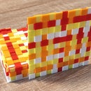
In the making of the photos, we used one color for all 68 LEDs and two colors, one for each half of the LEDs.
For the videos, filmed with my phone, I tried a red and blue "walking light effect" (I moved the LED light over the subject), and some WLED effects: the "Rainbow" effect on the rotating doll and the "Sparkle" effect on my Desktop Ring Clock. You can watch the merged videos below.
It might not be the best quality but as I told you, my daughter and I are just enthusiastic amateurs 😊
But NO Photoshop involved in the photo making!
Step 5: Conclusion
The Pocket RGB LED Light I have built is quite usable even if the light intensity of the device is quite low. To increase the value of the light intensity you can build and use more such devices, you can use more LEDs or even stronger RGB LEDs.
I also thought that two WS2812 LED arrays could be used with 64 LEDs each, as in the photo below,

the device could be smaller, it would have more LEDs (128) and much higher light intensity.
Thank you for reading so far, I hope you liked my article, I'm ready for your questions and observations as usual 😊

Participated in the
Lighting Challenge


