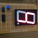
Introduction: Electronic Die
This project is an electronic die that generates the codes from 1 to 6 through 7 LEDs as outputs for showing the mentioned numbers while the inputs are the codes generated by a 7490 counter fixed to count from 000-101. For carring out the electronic die, it's necessary to design a decoder interface between counter and display by being this last one: the configuration of 7 LEDs referenced previously.
Step 1: List of Materials
From the list of materials, I changed the capacitor from 1uF to 1nF and the pushbutton switch Normally Closed to a Switch Push Button Tactile Single Pole Single Throw Off Momentary (On).
Materials:
1 PCB 9cm X 15cm
7 10mm Red LED
4 IC Socket 14-pin
1 IC Socket 8-pin
1 IC 7432 OR gate
1 IC 7408 AND gate
1 IC 7490 Counter
1 IC 7404 NOT gate
1 IC 555 Timer
1 Standard Regulator +5V, 7805
1 9V Battery Snap
1 Resistor 22K Ohm
1 Potentiometer 100K Ohm
1 Capacitor Monolithic Ceramic 1nF 50V
1 Switch Push Button Tactile Single Pole Single Throw Off Momentary (On)
1 9V Battery
Step 2: Installing the 10mm LEDs
Install the LEDs by inserting them in the PCB so that you can fold their terminals under the PCB. Once folded the ends of each LED, you should join and solder the cathodes each other.
Step 3: Installing the IC Socket 14-Pin
Install the IC socket 14-pin in the PCB and solder their pins # 7 to the LED's cathodes only.
Step 4: Schematic I: the Design
For interfacing the counter and the LEDs, it's necessary an interfacing element. That is, I have to design an appropriate decoder for this electronic die. Look at it so that you can understand it.
Step 5: Schematic II: the Project
Note the connections between D1 & D5, between D2 & D4, between D3 & D6 while D7 is connected alone. Look at the schematic so that you can realize that IC7490 counter will have to connected its pin-10 to GND and pin-5 to +5V too.
Step 6: Connecting the LEDs
In this step, do the following connections:
LED pin-anode D1 to D5 and IC 7432 pin-6
LED pin-anode D2 to D4 and IC 7432 pin-8
LED pin-anode D3 to D6 and IC 7408 pin-8
LED pin-anode D7 to IC 7404 pin-2
Step 7: Installing the Standard Regulator 7805
Continue with the rest of connections to the IC sockets previously installed, and also insert the 7805 in the PCB so that you can solder its pins under PCB.
Step 8: Install IC Socket 8-pin, Capacitor, Potentiometer, 22K-Resistor, Switch, and 9V Battery Snap
Once installed the components above mentioned, make the respective connections and follow instructions carefully. Also remember there are two schematics for your guide, the design and the project in itself with all of information what you need to complete your project successfully..
Step 9: Install the Integrated Circuits(IC)
For installing the integrated circuits, look at the photos above so that you can insert correctly the IC in their respective sockets and so you will almost be done your project.
Step 10: Complete Your Project
For completing your project, install the 9V battery. And for beginning to use the Electronic Die, you need to press the switch to watch lit all LEDs because the frequency is high and the changes too; however, when you leave of pressing the switch is set a number that can be among 1 to 6. If you are already in this step, congratulations and enjoy your project because now is yours.


