

Introduction: Arduino Wearable Keyboard Glove


The Arduino Wearable Keyboard Glove is an arduino powered gesture based input device. Essentially by moving a finger you can use a T9 based input system to type!
The device was initially developed as a proof of concept for a non-technical module at University, so the code and design pretty much fulfill the required function and nothing more. I do not have a background in computer science so the code for this is very basic and not the optimum solution in any way shape or form. However it can be used at a blueprint for users to develop and unlock much better functionality.
To make a pair of these gloves you will require: -
2 x Arduino Leonado (or Micro) Microcontrollers or equivalent
2 x ProtoBoards (2x3cm approx)
10 x 22kOhm resistors
2 x 10kOhm resistors
2 x mini push button
10 x 4.5'' Flex Sensors
Pair of gloves
Various: Assorted lengths of wire, headers, solder and velcro
It is worth noting the sensor arrangement was taken from another instructable and thus a more comprehensive guide is available here.
Step 1: Build the Prototype Shields


To take analogue readings of the flex sensors, potential divider circuit is used. I based my the potential divider configuration on an instructables by dschurman found here, but with the addition of a push button to turn the programme that reads the sensors on and off
Image 1 shows a hand drawn circuit diagram including labels to indicate where to connect the wires on the arduino.
My design required the protoboard to be mounted on top of the arduino as a shield, so headers were also soldered onto the board to provide a sturdy mount. This should be done to meet your own specification.
Images 2 and 3 show are how my proto shields looked once all the pieces were soldered together.
Step 2: (Optional) Solder Headers to Flex Sensors


Optional:
This was done to ensure the flex sensors could be re-used or replaced in case of component failure or a change of project requirements.
Soldering wires directly to the sensor would remove some of the added complication this step includes but I do recommend this step as the terminals/connectors attached the sensors feel very fragile, the headers were soldered on, then wrapped in electrical tape with a layer of heat shrink applied over. This gives the base of the sensor a significant improvement in rigidity and protection from over flexing which may otherwise damage the pins.
Step 3: Unit Assembly

Now it is time to attach your prototype board to the arduino shield as indicated by the circuit diagram and attach the flex sensors if they haven't been soldered on directly, it is also time to designate a unit as a left hand and one as a right as there is separate code for each.
Step 4: Fix to a Glove
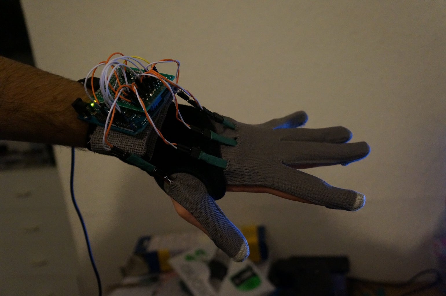
Fixing the units to the glove with some velcro is easy and the sensors can be sewn inside. The code is set up so that the metallic side must face downwards, partly to protect the metallic surfaces from unnecessary wear or damage.
To stop the sensors falling our i superglued the heatshrink to the gloves in the end.
The way it was done in my project required a frontless glove and wrist support mount to be used as it was design for users with limited dexterity (thus gloves are difficult to put on) however i wouldn't recommend this unless you have the same in mind.
Step 5: Upload Sketches to Arduinos
Using the Arduino IDE create copy and paste the following code into sketches and upload to the corresponding left and right units.
The Arduino Leonado can be recognised as a USB plug in and play keyboard when using the correct libraries called in the code. The board itself only outputs the digits 0 to 9 which are then translated by T9 program on the PC into letters. such that. 1 = a, 11 = b, 111 = c, 2 = d... etc. Currently the code works best with this free software which is in german but you simply run the software and right click the icon in the the bottom right of your screen and click the top box to turn the tool on and off (the bottom box quits and closes the app): Currently the mappings are:
--------------Left Hand------Right-----
Thumb -------1-----------------0
Index----------6-----------------2
Middle---------7----------------3
Ring-----------8----------------4
Little----------9-----------------5
This however can easily be changed from within the sketch.
Attachments

Step 6: Switching on & Calibration
Switching on:
As the leonado is powered by USB and communicates directly by USB the programme will not activate unless the button is pressed, this stops unintentional/unwanted entry as soon as a sketch uploads. a single press will illuminate the onboard programmable LED which indicated the flexread loop is running and thus bending a digit will cause an input, i recommend you try this outside of the arduino IDE. A subsequent single press or press hold will switch off the programme by exiting the loop. The LED will turn off to show this.
Calibration:
There are 5 thresholds in each sketch, one for each digit.
Nominally they work around 700 but increasing the value will decrease the sensitivity by increasing the flex required to trigger an input and visa versa. this is required due to the sensor being somewhat flexed during 'resting' positions of the hand and the +/-10% variability in the resistivity values.

Participated in the
Tech Contest


