

Introduction: Robotic Arm Gripper


This 3D printer-made robotic gripper can be controlled with two inexpensive servos (MG90 or SG90). We have used the brain shield (+Arduino) to control the clamp and the jjRobots control APP to remotely move everything over WIFI but you can use any other servo controller to move the gripper.
The problem with the servos is that they tend to get hot (even damaged) when you force then to apply force
continuously . So we are using the same solution LEGO uses: letting a rubber band to close the gripper . The servo will move the clamp to a certain position, from there, the rubber will close it completely. There is a small channel created to leave the horn moving freely once the rubber band starts to close the "hand", so we are not forcing the servo leaving it to "rest". Check the video below.
Depending on the force you want the rubber to apply when closing the clamp, (or the length of the rubber band you have) you will need to attach it to the different holes created for two M3 6mm bolts. (image below showing the bolts placed in the "default" holes). The closer to place the bolts to the "wrist" servo, the less strength will be delivered by the robotic gripper
 The rubber band attached to the "default" holes. If your use more than two bands the servo wont be capable of opening the nails.
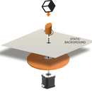
  The robotic gripper has been designed to close around the main Z axis. So the "wrist servo" gear will be the X,Y zero coordinate system.
 Step 1: Bill of Materials:
- 3D parts
- 1x 623zz ball bearing
- 1x M3 15mm bolt + washer
- 2x M3 6mm bolt
- 2x SG90 or MG90 (recommended) servos
- 1x M2.5 10mm
- some short rubber bands
- sticky EVA foam for increase the grip of the claw
Step 2: Assembling Your Robotic Gripper
1) Get the STL files from here (Thingiverse) Print them as indicated: 20% infill and PLA filament will do the job. Carefully clean the parts, remove any plastic burr, any friction between the elements will dis-align the claw when moving.

2) Insert the 623zz ball bearing into the left nail hole. You might need a small hammer to place it properly. A good alignment of the nail will depend on how well you have inserted the bearing in its channel. A 15mm M3 bol+washer will be used to attach the nail to the base. See upper photo for reference

3) Place the servos. In this case we are using two different servos model, the SG90 (blue) and MG90 (black). The difference: the gears, the MG90 has metal gears so it will last a little bit more than the SG90 (with Nylon gears). Additional, the MG90 will shows less backlash. Use the screws you will find in the servos´ bag to attach then to the base of the robotic gripper .
 Use the M2.5 bolt to fix the WRIST servo to the base. Check the photo below. Insert a single arm horn in the trench of the base. It will keep the servo aligned during the rotations of the clamp´s wrist.
  This photo shows the robotic gripper with the nails already placed. Ignore that at this point. You will assemble them later
Take a look to the photo above, In order to place the WRIST´s servo as it should, insert the horn as indicated.

Now it is time to place the robotic gripper servos. Pay attention to this step, otherwise, the claw will not close nor open properly. First, you will have to find the rotation limit of the servo turning the horn anticlockwise (photo 1). Once you have found it, take the horn out of the gear and place it back but as indicated in the photo number 1: completely horizontal. Then, rotate it 90ºclockwise, now it is ready to receive the NAIL. Cut the ends as indicated in the photo 2.
 Current state of the gripper. No nails in sight
 NOTE: This gripper has been designed to be 3D printed. It is easy to print, but as every 3D printer-made object it has it disadvantages. If you tighten up the screws too much, you can break the pieces or increase the friction unnecessary. If you notice that the nails of the clamp are not moving freely or there is too much friction, loosen the screws just a little bit.
 Attach the nails to the base as indicated above. Use the screw (or the bolt if you are using a MG90 servo) which comes inside the servo´s plastic bag and the M3 15mm bolt with the washer to connect the LEFT nail to the servo´s horn. DO NOT TIGHTEN THEM UP TOO MUCH, or the servo will have to work unnecessary to open and close the clamp. All the tolerances are quite small and if you force the plastic, it will bend increasing the friction.
Screw the 2x M3 6mm bolts as above/below for the rubber band

 EVA FOAM is recommended if you want to increase the grip of the nails. But you can use any other material you have around for the same purpose (rubber?)
Glue or stick the FOAM . You are almost there, just need to wrap the rubber band around the bolts heads and you are ready to go.

Step 3: NOTE: Simple Way to Remotely Control the Gripper
 Battery holder (9V) and the Brain shield to control the Robotic Gripper (+jjRobots control APP via WIFI)
 We have used the Brain shield and the Arduino Leonardo "combo" to control the gripper but any electronics capable of moving 2 servos (and delivering up to 0.7 Amperes per servo) will do the job. This clamps is the one used with the jjRobots SCARA Robotic ARM


