

Introduction: Save Water & Money With the Shower Water Monitor


Which uses more water - a bath or a shower?
I was recently thinking about this question, and I realized that I don't actually know how much water is used when I shower. I know when I'm in the shower sometimes my mind wanders, thinking about a cool new projects idea or trying to decide what to have for breakfast, while water is just gushing down the drain. It would be a lot easier to reduce my water consumption if I actually knew how many litres I was using each time!
I did a bit of research, and found that different shower heads can use anywhere from 9.5 litres (2.5 gallons) per minute to less than 6 litres (1.6 gallons) per minute, if you have a flow restrictor installed. A very old shower could use even more water.
I decided to design and build a device that would display the total volume of water used per shower, the cost of the water, and the flow rate. I've had this device installed for a few weeks, and it's really handy to have a live readout of the amount of water being used.
In this Instructable, I'll explain how I built this. Of course, you don't have to follow my steps exactly! It's always good to make use of parts you have lying around. I've included links to all the parts I used, or an equivalent part that will work.
Supplies
(All Prices in USD)
- Flow Sensor - $3.87
- LCD Screen - $2.29
- Arduino Nano - $1.59
- Boost Converter - $1.88
- LiPo Charger - $1.89
- Waterproof Toggle Switch - $0.93 (Not the exact one I used, but it should work)
- Waterproof Pushbutton - $1.64
- Standoffs, M3 Screws & Nuts - $6.99
- 2X Female 3.5mm Jack - $2.86 ea.
- Male 3.5mm Plug - $1.48
- 3.5mm 3' Cable Assembly - $3.57
- USB Cable Assembly - $1.74
- 1/2" NPS Female-to-Female Coupling - $1.88
- 500mAh 3.7V LiPo Battery - $3.91
Tools & Common Supplies
- Soldering Iron & Solder
- Wire
- Wire Cutters
- Wire Strippers
- Double-Sided Tape
- Phillips Screwdriver
- 3D Printer (Optional)
Step 1: Waterproofing

The most difficult aspect of this project is making the whole thing waterproof. Since it will reside in a shower, it must be able to survive extreme humidity and the occasional splash. About 75% of the total time spent on this project was figuring this part out.
The way I see it, there are two choices: design a custom 3D printed enclosure, or try to make it work with an off-the-shelf enclosure. Since I recently got my own 3D printer, I decided to go with the first option.
If you don't have access to a 3D printer, here are some off-the-shelf enclosures I've found that claim to be waterproof, and would probably work. Please note I have not purchased either of these enclosures so I make no guarantees that all the components will fit inside!
Banggood - 100x68x50mm Box with Transparent Lid - $5.35
Digikey - 130x80x70mm Box with Transparent Lid - $11.65
For this point onward, when I refer to the enclosure, I am talking about my 3D printed one.
Step 2: My Custom 3D Printed Enclosure!


After working in Fusion 360 for several hours, I came up with this enclosure. It has three circular cutouts to fit two female 3.5mm jacks and one toggle switch. The lid has a 16mm hole for the momentary pushbutton, and a rectangular cutout for the screen, as well as the four mounting holes to hold the screen in place. The lid is a separate part and has a lip to help prevent moisture ingress through the seam. The four holes on the corners of the box are to hold the lid on with 30mm standoffs. All the screw holes are 3mm in diameter, which fits an M3 screw.
You can download the STL files from my Thingiverse page. It can be printed without any rafts or supports, but I used supports just to be safe. I also used 100% infill. Since the walls are so thin, reducing the infill percentage doesn't really change the total print time or total material, so I just kept it at 100%.
To make the screen visible, it could either protrude through a cutout in the lid of the enclosure, or be placed behind a transparent window. Since the screen shouldn't be exposed to moisture, we're stuck with the second option. Unfortunately 3D printing with transparent filament is still in its infancy, so we'll have to get a bit creative.
My solution was to create a rectangular cutout in the lid, and glue in a piece of transparent plastic from some vegetable packaging. This technique can be used even if you aren't using my custom enclosure; simply cut out a rectangle with a utility knife or a Dremel. Of course, if you're using an enclosure with a transparent lid, this isn't needed at all.
The best source for transparent plastic that I've found is produce packaging. Usually spinach or other leafy vegetables come in large clear plastic containers. In my case, I used the packaging from a "pepper medley".
I wanted an overhang of 5mm to give plenty of surface area for gluing, so I cut out a 27x77mm rectangle of clear plastic. I had to trim the corners a bit so that the screws would fit. I squirted a line of superglue around the perimeter of the cutout, and then placed the clear plastic on. I added a bit more superglue around the edge after just to make sure it was sealed.
Pro-Tip: Place the part in front of a small fan while the glue is drying. As superglue dries, it tends to leave a vile white residue behind, which we certainly don't want on our transparent window. I used an old 12V fan from a computer power supply. I let the glue sit for 12 hours to make sure it was completely dry.


Step 3: Mounting the LCD Screen


Once the transparent window has dried, the LCD can be mounted. The LCD is a super popular 16x2 character display, with the I²C "backpack" pre-soldered to the back. I highly recommend getting this screen with the I²C interface. Wiring all the parallel lines is quite annoying and introduces more potential for mistakes - the I²C version only has two wires for power and two wires for signal.
I used four 10mm standoffs to mount the screen. The standoffs each have a male thread on one end and a female thread on the other. I put the male thread through the holes in the LCD and tightened an M3 nut to each one. Then I used four M3 screws to secure the female ends of the standoffs through the lid of the enclosure. I got this package of standoffs which has the 10mm ones to mount the LCD, and longer ones to hold the lid to the base. Plus, there are M3 screws and nuts, so you don't need to buy any additional hardware.
Be sure the nuts are very tight so that when you tighten the screws, the standoffs don't turn. Also, make sure you don't over-tighten the screws, or the plastic lid could deform and not seal properly.
The row of 16 header pins on the LCD should be on the top - make sure you don't mount the LCD upside down!
Step 4: Mounting the Momentary Button


I decided to use this sick-looking chrome button on the front panel. I've used them in previous projects and I really like the way they look. They're supposed to be waterproof, and they come with a rubber ring to prevent moisture from entering the enclosure through the threads.
This step is pretty straightforward. Undo the nut, but keep the rubber ring on. Insert the button through the hole in the lid, and tighten the nut from the back side. Avoid over-tightening the nut, or the rubber ring will be crushed and won't serve its purpose.
Step 5: Power and Charging Circuit


Now we will put together the battery power components. This includes the battery, master switch, battery monitoring/charging board, and the boost converter.
The battery I used is a 3.7V 1500 mAh single-cell lithium ion battery. The particular one I used was pulled from a broken Playstation controller. Any single-cell Li-Ion or LiPo battery will work, so long as it fits into your enclosure. This type of battery tends to be very thin and flat, so you could probably use one twice as big as mine without any problems. An 18650 cell would work, but it won't fit in my custom enclosure so you'll need to design your own, or use an off-the-shelf enclosure. If possible, I recommend using a salvaged battery (like I did) because shipping batteries is often expensive!
The battery should first be soldered to the TP4056 charging board. If you want, you can solder a JST RCY connector to the battery and charger for convenience (I did this), but it is not necessary. Be sure to observe the correct polarity as indicated by the markings on the charger board, as the board is not protected against reverse battery polarity!
Next, solder a wire from the positive output of the charger (located beside the positive battery wire) to the positive input on the boost converter. Then solder a wire from the negative output (located beside the negative battery wire) to the master toggle switch's common (centre) pin. Finally, solder a wire from the switch's normally-open pin to the boost converter's negative input. If you connect a multimeter to the output of the boost converter and turn on the master switch, a voltage should be displayed.
Since our Arduino, LCD screen, and flow sensor all need 5V, we must set the output of the boost converter to 5V. This is achieved by turning the knob on the potentiometer with a small screwdriver. With the master switch turned on, battery connected, and multimeter hooked up to the boost converter's output, slowly turn the potentiometer until the output reads 5V. It will be difficult to get a reading of exactly 5.000V but aim for a voltage between 4.9V and 5.1V.
Since my custom enclosure is held shut with several screws, we don't want to have to open the case every time it needs to be charged. I used a 3.5mm headphone jack for this. The exact connector I used is this one from Digikey (which is what the cutouts in my enclosure are sized for), but this one from Banggood should work as well.
First, I inserted the connector into the bottom-most hole in the enclosure. Since this will be unplugged most of the time, and therefore susceptible to moisture ingress, it is best to mount it on the bottom to prevent water from dripping inside. After installing the lock-washer and tightening the nut, I soldered two wires to the "tip" and "sleeve" tabs on the connector. The pinout of the connector is shown in one of my annotated images. I soldered the other end of the "sleeve" wire to the negative input on the charger, beside the micro USB port. Lastly, I soldered the "tip" wire to the +5V pad, on the other side of the USB port. The USB port on the charger will not be used, because it would be difficult to make the USB port penetrate the enclosure without allowing moisture in.
Step 6: Charging Cable


Since we are using a 3.5mm audio jack as our charging port, we need to make an adapter cable that has a male 3.5mm plug on one end, and a USB A plug on the other end. This will allow us to use any generic mobile device charger (such as an iPhone charger) to charge this device.
You could buy a USB cable assembly with a USB A connector on one end and tinned wires on the other end, but if you're like me, you probably have a dozen random USB cables lying around that you don't need. Rather than buying a USB cable assembly, I just got a micro USB to USB A cable that I didn't need and snipped the micro USB connector off.
Next, I stripped the white jacket off the cable to reveal only two wires inside: a red and a black wire. Some USB cables will have four wires: red, black, green, and white. The green and white are for data transfer, and can be ignored. Strip the insulation from the red and black wires only.
Next you will need a male 3.5mm plug. I used this one from Banggood. Solder the red wire from the USB cable to the middle tab (which is the tip of the connector) and the black wire to the long sleeve tab. See my photos for clarification.
I recommend always plugging in the 3.5mm plug before the USB plug, as the process of plugging in the cable could cause the plug to short across the metal receptacle.
Step 7: About the Flow Sensor


I picked up this flow sensor from Banggood for $3.87. Before using it, I decided to investigate how it works.
The design is surprisingly simple and ingenious. The electronics are completely sealed from the water. There is a free spinning propeller which spins slower or faster depending on the flow rate. At one point on the propeller is a magnet. On the outside of the sensor is a small compartment which contains a small PCB with two components: a resistor, and a hall-effect sensor. Every time the magnet passes by the hall-effect sensor, it toggles between high and low. In other words, it switches between 5V and 0V every time the propeller rotates.
To read the sensor, we apply +5V to the red wire, negative to the black wire, and read the digital signal from the yellow wire. In the photo of my oscilloscope you can see how the signal changes as the flow is turned on. At first, the signal is constantly zero volts. When the flow starts, the frequency of pulses quickly comes up to speed and reaches a steady state.
According to the datasheet, the sensor outputs 450 pulses per litre. This will be important later on when we are writing the software.
Step 8: Flow Sensor Wiring
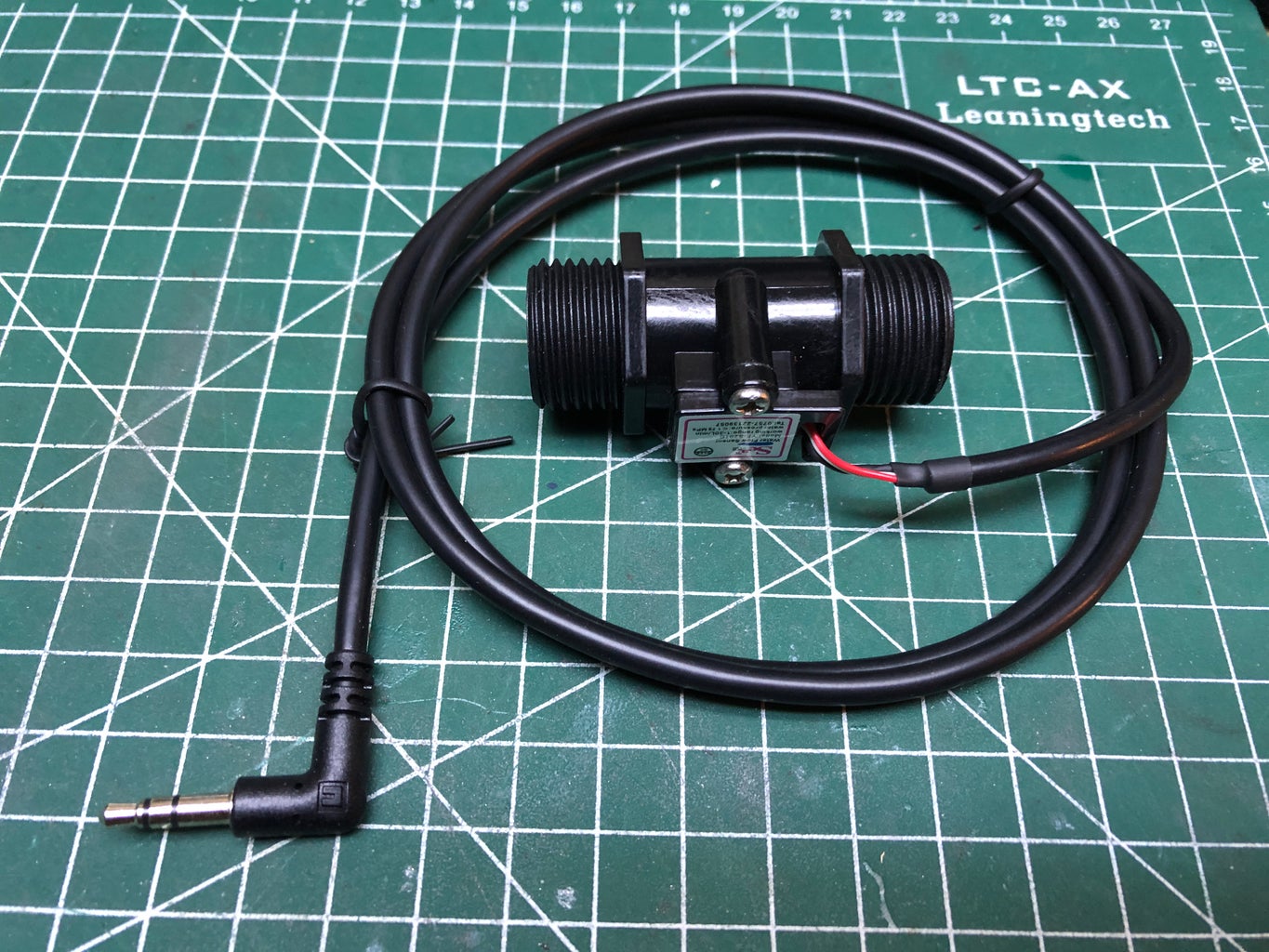


The flow sensor comes with a 3-pin JST-XH connector. This is not ideal because the wires are too short, and the connector has exposed contacts which can easily be shorted by stray water droplets. I ordered this 3.5mm audio plug cable assembly from Digikey. It is 3' long, which is the perfect length, and it has tinned wires, which makes it easy to solder. I don't recommend trying to use an old headphone cord, as those tend to have very thin enamelled wire, which is nearly impossible to solder.
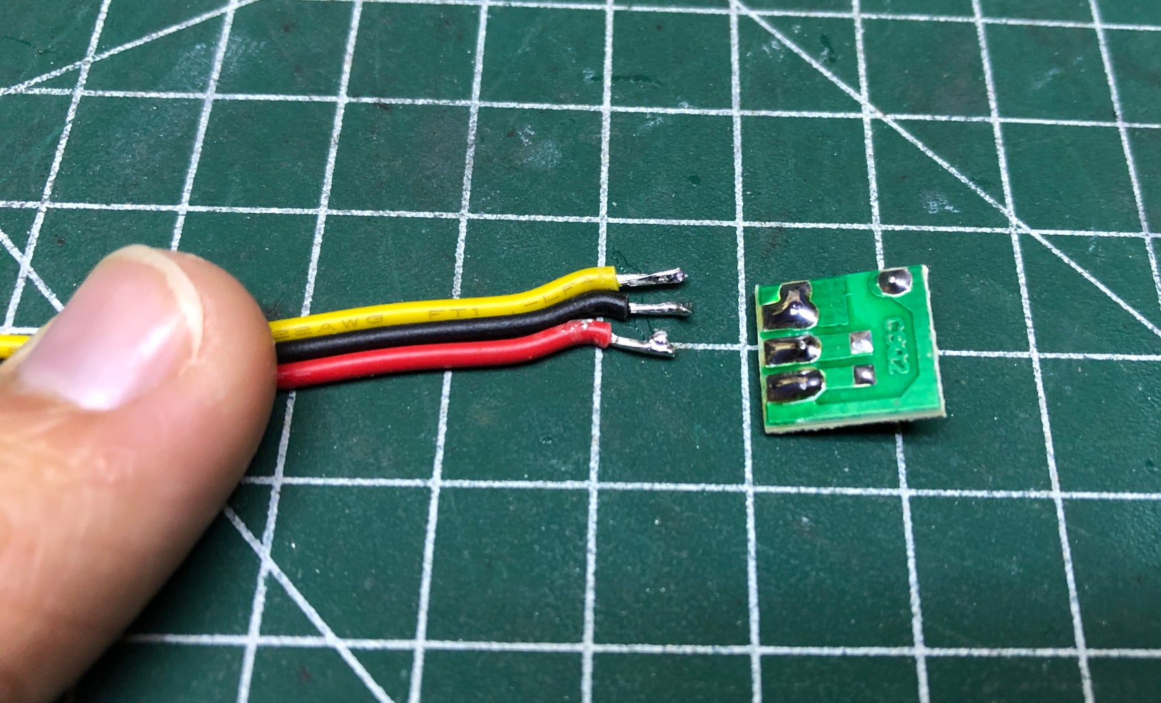
The flow sensor has a plastic cover, held on by two Phillips screws. Simply remove these screws, and pull out the circuit board. It isn't held in with any glue, it's just kept in place with the plastic lid. Next, desolder the three wires by heating them up with a soldering iron and lifting them off, one at a time.
Next, solder the 3.5mm audio cable to the pads. I suggest matching the colours the way I did. This configuration has +5V on the tip, signal on the ring, and ground on the sleeve. This is the same configuration used for the charging port, from step 6. If you accidentally plug the charger into the sensor port, or vice versa, there won't be any damage to the device.
Step 9: Installing the Flow Sensor


Up until this point, all our work has taken place in the workshop. But now, it's time to head to the bathroom!
First, I removed the shower head. This revealed a short bit of pipe protruding from the wall, with 1/2" NPS male threading. Conveniently, our flow sensor has the exact same thread size! The only problem is that the sensor has male threading on both ends, so we will need a female-to-female coupling.
At my local hardware store, there were 1/2" couplings in brass, iron, and PVC. The PVC one was the cheapest, so I got that one. Although in hindsight, the brass or steel ones would have looked nicer.
Once you have the coupling, simply screw the flow sensor into the coupling, and then screw the other end of the coupling onto the pipe. The flow sensor has an arrow to indicate the intended direction of flow. Make sure you don't install it backwards, or else the measurements could be inaccurate. Finally, screw the shower head onto the end of the flow sensor.
Of course, I am assuming your shower uses a 1/2" NPS thread, as mine did. If this isn't the case, you will need to get extra adapters.
Pro-Tip: Add some Teflon plumber's tape to all the threads before screwing the pieces together to prevent leaks. I didn't have any on hand, but I am planning to add this in the near future.
Step 10: Arduino & Perfboard


Since we're going to have to do a lot of wiring, it's a good idea to get a piece of perfboard to make things a bit tidier. I cut a rectangle of perfboard about 1" by 2". Next, I placed my Arduino Nano in the middle of the board and marked where the header pins went through. Then I cut two lengths of female headers, each 15 pins long. I soldered these onto the perfboard where I previously marked. This will allow us to remove the Arduino for programming.
Pro-Tip: Mark the orientation of the Arduino's USB port so that you always plug it into the perfboard the same way.
Step 11: Wiring Everything


Now it's time to solder everything together! I've included a complete wiring diagram, which you can follow, or see my written steps below if you prefer a more guided approach.
First, I cut some male header pins and soldered them onto the perfboard on the +5V and ground rails. Then I soldered two more header pins connected to pins A4 and A5 on the Arduino. These headers will allow us to connect the LCD screen using female-to-female jumpers.
Next, I soldered a pair of wires from the output of the boost converter to the +5V and ground rails. This will provide power to the Arduino, the LCD, and the flow sensor.
After that, I cut two wires and connected them to the terminals of the pushbutton. I soldered one wire to the ground rail, and the other to digital pin 3.
The last part to solder is the flow sensor. Since we already attached a 3.5mm plug to the sensor, we just need to solder a 3.5mm female jack. First I soldered three wires - one to each of the tabs on the jack. Then I inserted the jack through the enclosure and secured it in place with a nut. Finally, I soldered the sleeve to ground, the tip to +5V, and the ring to digital pin 2.
I chose to use digital pins 2 and 3 for the button and flow sensor because they are hardware interrupt pins. This will make it much easier to write the code.
Now we're finished soldering, but we still need to hook up the LCD. Since we soldered headers, we just need four female-to-female jumpers. Connect the "Vcc" pin to +5V, the "Gnd" pin to ground, the "SCL" pin to A5, and the "SDA" pin to A4. In order for the LCD screen to fit in the enclosure, we'll need to bend the header pins backwards. Bending the pins back and forth several times will fatigue the metal and cause the pins to break, so I recommend only bending them once, and do so with care.
Now the wiring is complete!
Step 12: Programming

Now that the hardware is all connected, we can program the Arduino.
I want the program to have the following features:
- On the first line, display a rapidly-updating count of the total litres
- On the second line, display the total cost of the water or the flow rate
- When the shower is running, the pushbutton toggles between showing the cost or the flow rate
- When the shower is not running, the pushbutton should clear all the data and reset the screen
- The sensor should be read using an interrupt routine to avoid gross polling methods
- When updating the screen, we should only update the values that have changed, rather than overwriting the entire screen each time (this would cause noticeable flicker)
The program follows a simple structure. By using the millis() function, we can create delays that don't actually halt the execution of the program. See this tutorial for an example of blinking an LED without using the delay() function.
The millis() function returns the number of milliseconds since the Arduino was turned on. By creating a variable "previousMillis" and subtracting Millis() - previousMillis(), we can see the elapsed time since previousMillis was updated.
If we want something to happen one per second, we can use the following code block:
if((millis() - previousMillis) >= 1000){ previousMillis = millis(); toggleLED();}This checks if the difference between millis() (the current time) and previousMillis (the last time) is greater than or equal to 1000 milliseconds. If it is, the first thing we do is set previousMillis equal to the current time. Then we execute whatever additional steps we want. In this example, we're toggling an LED. Then we exit this block of code and finish the rest of the loop() function, before going back to the start and repeating it all over again.
The benefit of using this method over the simple delay() function is that delay() puts a gap of time in between the instructions, but doesn't account for the time it takes to execute the other instructions in the loop() function. If you are doing something that takes longer than just blinking an LED, such as updating an LCD screen, the time it takes is not negligible, and after a few cycles it will add up. If you're updating the LCD screen on a clock, it would quickly become inaccurate and fall behind.
So now that we understand the overall structure of the program, it's time to insert the instructions. Rather than explaining every single line of code here, I suggest you first read over the attached flowchart, which gives a high-level overview of what the program does.
Once you've seen the flowchart, take a look at the attached Arduino code. I have commented almost every line to make it clear what each line is doing.
There are a few parts in the code you might want to change. Most importantly is the cost per litre. In my city, the water costs 0.2523¢ per litre. Locate the following line, and change that value to match the cost where you live:
const float COST_PER_LITRE = 0.2523; // cost per litre, in cents, from city website
If you prefer to use gallons over litres, change all the "LCD.print()" lines that refer to "L" or "L/s" to "G" or "G/s". Then delete the following line:
const float CONVERSION = 450.0; // keep this uncommented for litres
...and uncomment this line:
const float CONVERSION = 1703.0; // uncomment this and delete the line above for gallons
There is one more oddity you may have noticed in my code. The default character set does not include the "¢" character, and I didn't want to use dollars, because the cost would show up as "$0.01" or less for the majority of the time. Therefore, I was forced to create a custom character. The following byte array is used to represent this symbol:
byte cent_sign[] = {<br> B00100, B00100, B01111, B10100, B10100, B01111, B00100, B00100};After creating this array, the special character must "created" and stored.
lcd.createChar(0, cent_sign);
Once this is done, to print the custom character we use the following line:
lcd.write(byte(0)); // print cents sign (¢)
The LCD can have up to 8 custom characters. More information on this is here. I also came across this helpful online tool that lets you draw the custom character using a graphical interface, and it will automatically generate the custom byte array.
Attachments

Step 13: Closing the Lid


Finally, we're nearly finished!
It's time to stuff all the electronics into the enclosure and hope the lid closes. But first, we need to attach the 30mm standoffs. The package of standoffs I bought doesn't include any that are that long, but it does come with 20mm and 10mm ones that can be attached together. I screwed four standoffs into the holes on the bottom of the enclosure with four M3 screws (see images 1 & 2). Be sure to tighten these securely, but not too tight or you risk breaking the plastic enclosure.
Now we can fit all the electronics inside. I attached the charger and boost converter to the lid with double-sided tape, as seen in the third image. Then I wrapped some electrical tape around the exposed metal on the two 3.5mm jacks, just to ensure nothing gets shorted by contacting the connectors.
I was able to make the Arduino fit by placing it on its side, in the bottom left corner, with its USB port facing the right. I used more double-sided tape to secure the battery to the bottom of the enclosure beneath the LCD screen.
Finally, once everything is jammed more or less securely into the box, the lid can be screwed down with four more M3 screws.
Step 14: Testing


First plug in the 3.5mm connector from the flow sensor. I recommend doing this before the device is turned on, because it's possible for the plug to make unwanted connection as it's being inserted.
Next, turn on the master power switch. While there's no water running, the front panel button shouldn't do anything besides clearing the total and clearing the screen. Since the total will be zero by default, the button won't appear to do anything yet.
If you turn on the shower, the total should start increasing. By default, the cost is shown. If you press the front panel button, the flow rate will be displayed on the bottom line. Pressing the front panel button will toggle between showing the flow rate and showing the cost, so long as the shower is running. Once the shower stops, pressing the front panel button will reset the measurements and clear the screen.
Mounting
How you choose to mount the device depends on the layout of your shower. Some showers might have a ledge close enough to the shower head that you could simply place the device there. In my shower, I have a basket attached with suction cups that I placed the device inside of. If you don't have the luxury of a ledge or basket, you could try holding the device to the wall with a double-sided suction cup. This will only work if you're using an off-the-shelf enclosure which has a smooth backing, or you printed my custom enclosure on a printer with a glass build plate. If your enclosure has a rough backing (like mine does), you could trying using some double-sided tape, although this might leave some residue on your shower wall if you try to remove the device.
Troubleshooting
Screen is on, but backlight is off - make sure the jumper is installed on the two pins on the side of the I²C module
Screen is blank, with backlight on - check that the I²C address is correct by running the I²C scanner
Screen is on, but values stay zero - check that there is a signal coming from the sensor by measuring the voltage on pin 2. If there is no signal, check that the sensor is connected properly.
Screen is blank with backlight off - check that the power LED on the Arduino is on, and check that the screen has power
Screen turns on briefly, then everything stops - you probably set the voltage from the boost converter too high (the components can't handle more than 5V)
The device works, but the values are wrong - make sure the flow sensor you're using has the same conversion factor of 450 pulses per litre. Different sensors may have different values.
Step 15: Now Start Saving Water!
Improvements
The current version of the software works well enough, but eventually I'd like to add the ability to have different users (family members, housemates, etc.) The device would store each person's stats (total water & total number of showers) to display an average water use for each person. This could encourage people to compete to use the least amount of water.
It would also be cool to have a way to export the data to be viewed in a spreadsheet, so that it could be graphed. Then you could see what times of the year people have more frequent and longer showers.
These features would all require the use of EEPROM - the Arduino's built-in non-volatile memory. This would allow the data to be retained even after the device is turned off.
Another useful feature would be a battery indicator. Right now, the only indication that the device needs to be recharged is when the battery manager board cuts off the power. It would be easy to hook up an extra analog input to measure the battery voltage. A voltage divider wouldn't even be needed since the battery voltage is always less than 5V.
Some of these ideas are bordering on feature creep, which is why I didn't develop the software any further.
The rest is up to you!

First Prize in the
Sensors Contest


