

Introduction: The Floating Arm Trebuchet


The floating arm trebuchet is a modern take on an ancient war machine. This variation features a drop channel, which allows the counterweight to fall straight down rather than swing with the arm. This is a more efficient way to transfer potential energy into kinetic energy at a small scale. A pair of wheels allows the arm to roll along glide rails as the counterweight falls. This design is more complicated to build than a traditional trebuchet, however the launching mechanism is more effective and much more gratifying to behold!
You can find the lesson plan, 1-page project sheet, and more project ideas at STEM-Inventions.com
Step 1: Tools and Materials

This project requires precise measurements to work consistently. Therefore, use only woodcraft that is perfectly straight and well-formed. Discard warped or defective pieces before building.
Please message me to report broken links.
You'll need:
- hot glue gun with safety tip
- six 12" (30.5 cm) paint stirrers
- utility knife
- ruler
- Drill
- 1/4" and 1/8" drill bits
- seven 12" (30.5 cm) square dowels, 1/2" (1.3 cm) wide
- 1/4" (6 mm) bolt, 5" (12.5 cm) long
- seventy 1/4" (6mm) fender washers
- three 1/4" (6mm) hex nuts
- 1/4" (6mm) wooden dowel
- masking tape
- bamboo skewer
- at least 30" (76cm) of string
- paperclip
Material substitutions
Paint stirrer: ruler, wood shim, craft sticks, or another flat, rigid strip of wood
When you make a purchase through these links, I may earn an affiliate commission at zero cost to you.
Step 2: Prepare the Pieces

Prepare the pieces:
- Cut two 12" (30.5 cm) paint stirrer into four 6" (15 cm) pieces
- Split two of the 6" (15 cm) pieces down the middle
- Cut the bottom of the split pieces at approximately a 45° angle
- Cut 2 paint stirrers into four 5" (12.5 cm) pieces, leaving two 2" (5 cm) pieces
Step 3: Build the Base and Drop Channel


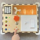
Base and Drop Channel
- Form the base using two whole paint stirrers and the two 6" (cm) pieces. Center and hot glue the ends of the long pieces to the shorter cross pieces.
- Create the drop channel: Hot glue four square dowels upright at the center of the base. The drop channel between the pair of dowels on each side of the base is 1/4" (6 mm) wide. The space between the dowel pairs across the base is 1 1/2" (4 cm).
Step 4: Build the Glide Rails


Glide Rails
- Use the 5" (12.5 cm) pieces of paint stirrer and the four 6" (15 cm) square dowel pieces to form the glide rails.
- The glide rails do not cross into the drop channel.
- Use the 2" (5 cm) pieces of paint stirrer to add structural support to the glide rails and to help maintain a uniform gap.
- Glue the split paint stirrer pieces at an angle to support the glide rails and drop channel. The tops of these pieces have been trimmed for a cleaner look.
Step 5: Assemble the Throwing Arm


Throwing Arm
- Get ready to assemble the counterweight and trebuchet arm. You’ll need all the hex nuts and all but 10 of the washers. The washers and nuts will be assembled onto the bolt in the order shown.
- Drill four 1/4" (6 mm) holes into a square dowel. One hole should be near the end of the dowel, and the other three are spaced 1" (2.5 cm) apart, starting 2" (5 cm) from the first hole.
- Assemble the metal components with the square dowel in the center. Insert a 2" (5cm) piece of round dowel into one of the remaining holes. Wrap layers of masking tape around the round dowel until the thickness is slightly larger than the center of the washers. Snugly fit 5 washers onto each end of the dowel. The dowel should spin freely, but the washers should remain in place. Cut off any excess dowel to prevent it from getting caught on the drop channel beams. This will be the roller that travels over the glide rails.
Step 6: Make the Trigger


Trigger
- Set the counterweighted arm into the drop channel. Give it a quick test by pulling the arm back and letting it go. The arm should smoothly swing forward as the counterweight falls.
- Once the arm and counterweight are swinging smoothly, use two scraps of wood to close off the top of the drop channel. Drill two sets of holes using the 1/8" (3 mm) bit for the trigger pins.
- Create the trigger by tying one 30" (76 cm) piece of string to two 2" (5 cm) pieces of bamboo skewer.
- Set the trigger by raising the counterweight above the holes and inserting the pins. The pins should fit in the holes loosely. The goal is to use the weight of the counterweight (rather than friction) to hold the pins in place.
Step 7: Firing Pin and Projectiles


Firing Pin
- Straighten out a paperclip and then fold it in half. Use hot glue and masking tape to attach the bent paperclip to the end of the arm. Bend the rounded end of the paper clip upward slightly. This is where the projectile will be attached.
Experiment with the paperclip angle
The angle of the bend in the paperclip will determine the timing of the projectile’s release. A straighter paperclip will result in a quicker release and a higher trajectory. A paperclip with greater curve will give a delayed release and a straighter trajectory. There’s no “best” angle—it depends on what kind of trajectory you want to achieve.
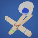
Projectiles
2. Create some projectiles from household items. All you need is a small and dense object with a string tied to it. A loop at the end of the string allows the projectile to attach to the paperclip.
The form and density of the projectile have a big impact on how well the trebuchet performs. The string length will also affect how far your projectile will launch. Experiment with a variety of items to find which one will go the farthest. Get started with small but dense items.
Step 8: Load and Fire!


Get ready to fire!
Loop the string onto the paperclip and place the projectile onto the base. Stand to the side of the trebuchet to avoid being struck by a wayward projectile. Give the trigger a swift tug to release the pins!
Pro Tip: Maximizing performance
There are several subtle but key variables that influence how well the trebuchet performs. The rollers in the arm can be positioned into different holes, thus altering the position of the fulcrum. The hole nearest the end of the arm maximizes the speed of the projectile, but it may not perform as well with heavier projectiles. As mentioned, the angle of the paperclip is a key variable, as well as the type of projectile, and the length of string that it’s attached to.
Step 9: Troubleshooting

This project requires precision to work consistently. Here are my troubleshooting tips that I discovered while tinkering and developing this project plan:
The axles for the glide wheels bumps into the drop channel beams.
Trim the axle until it is flush with the wheels. If the washers start falling off, rub a little bit of hot glue on the outside of the axle and the washer to keep them in place.
Reposition the drop channel beams further apart.
The counterweight hits the glide rails while falling down.
Make sure the glide rails do not intersect the drop channel at all.
Make the drop channel gap slightly wider.
The throwing arm hits the drop channel.
Make sure the throwing arm rests between the glide rails before launch as shown in the image above.
Reposition the drop channel beams further apart.

Runner Up in the
String Challenge

Runner Up in the
Make it Move Contest 2016


