

Introduction: Wooden Digital Clock


Wooden Digital Clock with
- Time, Temperature, Humidity, Alarm
- WiFi controller through web browser
- Advance display config
- Stop alarm by vibration sensor
size : 64 x 64 x 79 mm
i use PLA with wood veneer instead of full wood
my room's too small for put woodworking tools
If want view detail all steps, you can watch video
Attachments

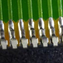
Step 1: PCB - Display


This step for make PCB (two layer) display module (if cannot do, you can find PCB Manufacturing Service)
I use MAX7219 for led driver and display with Led CEM3491, it have two dots for sec and upper dot for temperature
But CEM3491 is Common Anode, MAX7219 for drive Common Cathode, so must reverse pin Digit and Segment
Material list :
- (x1) CEM3491BY (0.39" Common Anode 4-Digit 7-Segment Display Amber Color)
- (x1) MAX7219 (Led driver display)
- (x1) 10k Resistor
- (x1) 10uF Capacitor
- (x1) XH2.54-5P (5Pin Straight PCB Male Box Header Bar Connector)
Step 2: Program


I have complete program firmware, you just upload it to STM8S005C6T6 by software STVP-STM8 with file controller.s19
STVP-STM8 : http://www.st.com/en/development-tools/stvp-stm8....
hardware for upload : ST-LINK
if see "PROGRAM MEMORY programming completed" it mean done
about upload firmware, view detail in video at 10:35
Step 3: PCB - Controller


Next for solder microcontroller STM8S005C6T6 and other parts for complete PCB controller
button for reset wifi config, just hold down 3s and buzzer will fire beep sound
Material list :
- (x1) STM8S005C6T6 (Microcontroller)
- (x1) ESP8266-12 (WiFi module)
- (x1) ASM1117-5.0 (voltage regulators 5V)
- (x1) ASM1117-3.3 (voltage regulators 3V3)
- (x1) 470uF Capacitor
- (x1) 1uF Capacitor
- (x3) 10uF Capacitor
- (x2) 4.7k Resistor
- (x1) Mini Pushbutton Switch (4Pin)
- (x1) SW-420 (Vibration sensor)
- (x1) DS1307 (Real Time Clock)
- (x1) 32.768 khz crystal
- (x1) CR2032 battery
- (x1) CR2032 battery holder
- (x2) XH2.54-2P (2Pin Straight PCB Male Box Header Bar Connector)
- (x1) XH2.54-5P (5Pin Straight PCB Male Box Header Bar Connector)
- (x1) XH2.54-4P (4Pin Straight PCB Male Box Header Bar Connector)
- (x2) Cable Double Connector XH2.54-2P
- (x1) Cable Double Connector XH2.54-5P
- (x1) Cable Double Connector XH2.54-4P
Step 4: External Interactive


solder external interactive parts : dc jack power, switch, DHT22, buzzer
don't forget put heat shrink tube before solder
and make sure solder jack dc exactly polarity (+ -) with PCB controller
Material list :
- (x1) PCB prototype double side
- (x1) DHT22 (Temperature, Humidity sensor)
- (x1) C1815 Transistor
- (x1) XH2.54-4P (4Pin Straight PCB Male Box Header Bar Connector)
- (x1) DC power jack
- (x1) Buzzer 5V
- (x1) Rocker Switch On/Off
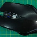
Step 5: Box Case


3d print with PLA filament 1.75mm, layer height 0.16mm
complete SLT file in attachfile, or build for yourself with custom size
Step 6: Assembly


link connector cable and arrange internal, external parts for fit with box case
require M2 bolt (x9)
don't forget put CR2032 battery
Step 7: Wood Skin


I use wood veneer sticker for apply skin simple
Step 8: Complete & Test


Input 9v power supply and turn on switch button to on wifi
Default mode is AccessPoint (mean wifi create from wood clock)
mode AccessPoint have default SSID : noname (no password) with ip 192.168.4.1
with mode Station (mean wood clock will join to other wifi) your device and wood clock must in same wifi network
after switch on and wifi ready, Led will show 4 number of ip, ex : 192 (--blink--) .168 (--blink--) .4 (--blink--) .1
then visit ip on browser, you'll see control page with 7 menu
- Home : display curent Time, Temp, Humi, Heat-Index
- Display : change Brightness and Type display time
- Time : config current time and digits
- Temperature : config temprature
- Humidity : config humidity
- Alarm : config alarm and sound
- Wifi : config wifi

Runner Up in the
Lights Contest 2017

Runner Up in the
Internet of Things Contest 2017


