

Introduction: 12 Arduino Projects for Beginners — With Code


Have you ever wanted to learn how to write code for the Arduino board by working on fun Arduino projects, but never really knew where or how to start?
Well, I believe that every Maker has already been there. That’s the reason why I have create a collection of Arduino projects with increasing level of difficulty for anyone to start getting more familiar with programming the Arduino board. The projects will allow you to learn the basics of the Arduino in a very efficient manner, and take you step by step to building more complex projects.
Step 1: Arduino Projects
This collection of Arduino projects from very basic to more advanced includes:
- LED Blink
- LED button
- LED brightness
- Traffic Light Controller
- Servomotor Control
- Smart Night Lamp
- Play Tunes
- Voice control
- and much more…
These Arduino projects can inspire you for your own projects. If you want to learn more, you can take our complete Udemy online course: Arduino and Robotics.
The projects source code can be found on Github. Without further due, let’s start!
Step 2: LED Blink
The “LED Blink” is for the Arduino the equivalent of the “Hello world” in computer programming, where you will need to write a code to have the sentence “Hello world” displayed in the console of a computer. Not really exciting, but it gives a hint on the inner workings of the Arduino board. Each Arduino board comes with an on-board LED that can be used for this purpose. The project toggles the default LED of the Arduino board located on the pin 12 (ledPin) ON and then OFF every 2 seconds (delayTime, note: 2s=2000ms).
Step 3: LED Button Control
Once more comfortable with the “LED Blink” project, the more natural way to move forward is to add more control on our LED. We can use a push button for this purpose and only switch the state of the LED when the button is pressed down. The “if” statement in line 14 is used to check for a change of state of the button, in this case state transition “button up” to “button down”. The code only toggles the state of the button 200 ms after the button is pressed in order to filter the input. This process is called denouncing.
Step 4: LED Brightness Control
The Arduino projects are starting to get more interesting as we move forward in this post. So far, we have only controlled the LED in a binary form. ON or OFF depending on various events and inputs. But wouldn’t it be nice to control the brightness of our LED? Well that’s exactly what we will do in this project!
Controlling the brightness of an LED is equivalent to controlling the voltage on the pins of the LED. To do that, we will use the PWM output of the Arduino board. With the LED connected to pin 3 and a potentiometer connected to the analog input A0, the code bellow changes the brightness of our LED by rotating the potentiometer.
Step 5: Traffic Light
To continue and end our Arduino projects on LEDs, let’s build a traffic light controller with 3 LEDs (Red, Yellow, Green). Each LED should light up one after the other after a specified amount of time to emulate a traffic light. For further improvements, a button can also be connected to the Arduino to emulate, a “Pedestrian crossing” button that makes the traffic light turn to Red on demand.
Step 6: Servomotor Control
Hoora!!! It is great to have been able to explore small but interesting projects with LEDs. But wouldn’t it be great to see something physically moving and controlled by the Arduino?
We can use a servomotor for this. A servomotor is controlled almost in the same way as the LED is controlled in the “LED brightness control” project, but there is more to it than just setting the PWM output of the Arduino to a specific value. This is when libraries comes very handy, we can use the “Servo.h” library provided with the Arduino development environment to make it very simple to control a servomotor. We include the library in our project and use the functions “attach()” and “write()” to respectively configure the PWM output port to be used with a Servomotor and set the position of the servomotor. The position of the servomotor will oscillate between -180° to +180°.
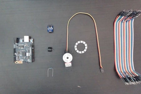
Step 7: Smart Night Lamp
Let’s now put everything together into a single project. The Smart Night Lamp will use all the knowledge that we have acquired so far. We will change the brightness of 3 LEDs by using a potentiometer, and set the angle of a servomotor to it’s current value to indicate the brightness level. Note that a single multi-color LED can also be used instead of the 3 LEDs, this will result in effectively having different colors. A multi-color LED has 3 pins and allows to control it’s Red, Green and Blue value to create any color in the visible spectrum. For simplicity, we will stick here to what we have already learned so far, but for more advanced learners, I would recommend to give a go and use the multi-color LED instead.
Step 8: Play Tunes
That’s an exciting Arduino project, being able to play various tunes with the Arduino board. Although this may seam daunting at first and seems to require a deep knowledge of the musical language, it is fairly easy to produce sound using the Arduino board. By connecting a buzzer on a PWM output of the Arduino board and using the built-in function “tone(pin, frequency, duration)” it is possible to generate a tone of any frequency for a specific duration. A melody is just a succession of those tones. In this example the frequency and the duration of each tone is stored in arrays and are later on played by reading each value in the arrays.
Step 9: Voice Control
Who has never dreamed of interacting with an advanced artificial intelligence such as Jarvis first seen in the movie Iron Man? Well it would be even better to build one by yourself :)!
Connecting a microphone to the Arduino board will allow us to just do that. Voice is just another analog signal that we can capture by using an analog input. By connecting a microphone on the analog pin A0, we can capture our voice as a signal that changes over time. The simplest way to integrating voice control in any application is to just use the amplitude of the vocal signal to generate an action once this amplitude is above a specific value. In this project, we will turn on an LED by speaking into a microphone. We detect the amplitude of the vocal signal (how loud the signal is) and turn on an LED if the signal is above a threshold. Any loud sound can change the state of the LED in this project, this can serve as the basis to implementing more complex behaviours.
Step 10: Conclusion
Congratulations, if you have reached so far in this post, they are even more exciting projects in the github repository that involves using the Arduino 101 board and create cool project with functionalities only available on this board such as accelerometers, timers, Bluetooth, etc…
Below are some useful links:
Udemy course: Arduino and Design : Make Your First Robot
Github: Projects Code
Hope you enjoyed this post, it will be updated as more projects are added to the github repository, so stay tuned and keep coding awesome projects.


![Tim's Mechanical Spider Leg [LU9685-20CU]](https://content.instructables.com/FFB/5R4I/LVKZ6G6R/FFB5R4ILVKZ6G6R.png?auto=webp&crop=1.2%3A1&frame=1&width=306)


