

Introduction: $2 Arduino. the ATMEGA328 As a Stand-alone. Easy, Cheap and Very Small. a Complete Guide.


In this instructable you will learn how to use the Arduino ATMEGA328 microcontroller chip as a stand-alone microcontroller.
They cost only 2 bucks, can do the same as your Arduino and make your projects extremely small.
We will cover the pin layout, how to make it ready for the Arduino software by burning a bootloader and how to upload sketches.
Watch the rest of this instructable to find out how you can make your Arduino projects smaller and cheaper in no time.
Step 1: Parts List
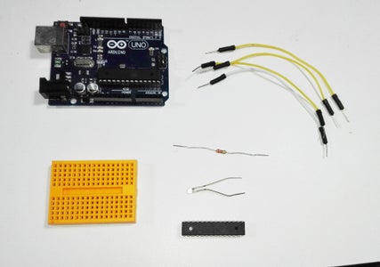
- 1 Arduino
- 1 ATMEGA328P-PU chip. I got mine here:
- Breadboard
- Wires
- Optional: LED and 330 ohm resistor for testing
Step 2: Download and Install Library


An Arduino board comes standard with a 16MHz external oscillator.
We don't really need this 16MHz oscillator as the ATMEGA328P-PU has a 8MHz oscillator build in.
In order to make this chip work as a stand-alone microcontroller at 8MHz, we have to download and install a library for our Arduino environment.
To do this, click the link that match your Arduino version to download the zip file.
It will be eater 1-6-x.zip, 1-5-x.zip or 1-0-x.zip
Next we have to find the Arduino sketchbook folder by clicking on File → preferences → “Sketchbook Location”. In my case “C:\Users\tomtomheylen\Documents\Arduino” this can be different in your case.
Copy the location and go to “this pc”, paste it in the bar and press enter.
If you see a folder named “hardware”, open it.
If not, make a new folder named “hardware” by right clicking and select “new → folder” and type “hardware”. Now open it.
Move the breadboard folder from the zip archive to the “hardware” folder.
Restart your Arduino IDE and go to “Tools → board”.
If everything is OK, you should see in the list “Atmega 328 on a breadboard (8MHz internal clock)”.
The most difficult part is done now so let's have some fun pumping life in that ATMEGA328.
Step 3: Burn Bootloader

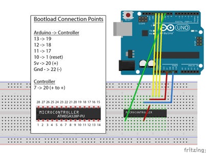
These ATMEGA328 microcontroller chips usually come empty. To make them work with the Arduino IDE, we have to do something what's called “burning a bootloader”. It is a tiny bit of code we burn on the chip so it will understand the Arduino software.
To do this, connect your Arduino to your computer and go to “File → examples → ArduinoIsp” and select “Arduino Isp”. Upload this sketch to your Arduino and disconnect from your computer.
Next we connect the Arduino with the ATMEGA328 as you can see in the image.
Note the half circle on the chip. Make sure it is on the correct side.
Now connect your Arduino and in the Arduino IDE go to “tools → Programmer” and select “Arduino as ISP”.
Next go to “Tools → Board” and select “Atmega 328 on a breadboard (8MHz internal clock)”.
Now go to tools and select “Burn Bootloader”.
Your bootloader is burned and your chip is ready to upload sketches!
In case you have an error message, unplug your Arduino and repeat the previous steps.
Step 4: Uploading Sketches
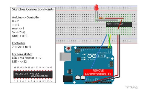

To upload a sketch you have to remove the ATMEGA328 chip from the Arduino board and connect to the breadboard as shown in the image.
You can also use a USB to serial programmer like the FT232RL to do this. I have made a mini instructable on this here:
I have connected a led with resistor on the board to test the blink sketch.
Here is how to use this image for the
pin layout.
So for example if you initialize pin 13 in the IDE, it represents pin 13 on the Arduino board or pin 19 on the ATMEGA328 chip.
Congratulations, you made it! You can now start soldering your own minified Arduino projects for next to nothing.
Step 5: A Few Helpful Tips

I will end this instructable by giving you a few more more helpful tips:
If you solder a project, you need to use a 28 pin DIP socket and add the ATMEGA328 after soldering the project.
I got mine here
It is good practice to solder some malevor female header pins to the 3 first legs so you can still change or upload sketches if needed.
If your micro controller is behaving weird, you can add a 10 to100 uf capacitor in between + and -.
Make sure when you order the chip that it is the ATMEGA328P-PU.
Step 6: Final Note
Did you like this instructable, please click the Favorite button and subscribe.
Also check out my "How to fix Chinese Arduino clones" instructable.
See you in the next Instructable.
Thanks,
Tom Heylen
Facebook: https://www.facebook.com/OfficialTomHeylen
Donate to help me keep doing this work: https://www.paypal.me/TomHeylen/2usd


