

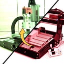
Introduction: Automated Tablet Weaving Loom


Tablet weaving can be really difficult, keeping track of what was your last step is nearly impossible for me. So I let arduino remember that, and when I am at that, I'll let it even to rotate the tablets :-).
Supplies
Frame:
- Lots of PETG 3D printing filament
- Threaded rods M8, M5
- Nuts, Bolts, Shims, M8, M5, M3
- Dry wall screws
Moving parts:
- Roller skate bearings
- 5x16x5mm 625ZZ
- for tablet gears
Electronics:
This is what I've used, not neccesarily the best way.
- Arduino UNO
- 74HC595 expander
- For the solenoids
- ULN2003AN
- For the solenoids
- Breadboard
- A4988 stepper driver
- Nema 17 stepper motor
- Some kind of Power supply
- (optional) Ky-040 rotary encoder
Tools:
- 3D printer
- I've used Prusa MK3S+
- Drill
- Tap & die set
- Wrenches, screwdrivers and all that stuff...
Step 1: What Is Tablet Weaving


Tablet weaving is a way to create handmade strips of cloth, with beautiful patterns. Strips are usually made out of wool, and you need a weaving loom and tablets to be able to create one. They are used, for example, to decorate your medival outfits :-).
Mentioned tablets are made out of slippery material (so the wool won't catch), playing cards cut to size are the most common material. During weaving, you rotate some of them (to create the pattern), according to pattern instructions which can be quite tedious and prone to error. Which is why I decided, to create Tablet weaving loom, that rotates tablets for you (and most importantly, remembers which ones and when).
Btw. great tutorial on tablet weaving patterns is from Manj_who, check it out!
Step 2: Pencil Sketching

First of, I took some paper and sketched basic idea of how the tablets should work. There are few designing challenges to overcome.
Warp (<- all the unweaved) yarns are all around the tablets, so if I want them to rotate by themselves I cannot use axle because it would interfere with the yarns (yarns would wrap around the axle).
Also, each tablet should rotate clockwise and counterclockwise independently. So to have it even more difficult, I decided to use one beefier stepper motor, to power all the tablets and a clutch like mechanism to hook up individual tablets.
Step 3: Tablets


To be able to rotate them with motor I made tablets as a gear with four holes, instead of square. I planned that it would be mounted in three points around the gear (but still be able to rotate).
I decided, that three points are gonna be bearings, fastened to some kind of construction. For the tablets to rotate on mentioned bearings smoothly, I modeled the tablet gear part with an offset, which is smooth without teeth. Later I changed the design of the tablet gear to use less filament.
Tablet gears have matching holder which holds bearings in place, there is even raised area, for bearing to rotate freely (and not get squished between walls of the holder).
Tablet gears were 3D printed. I later realized, that tablets could be real gears without smooth offset, and instead of bearings I could use small gears, which would be easier for modeling in CAD software. I am glad I haven't done that, because it would eat a lot more 3D printing time and would be less smooth of a motion.
Bearings are cheap 5x16x5mm 625ZZ bought from china.
Step 4: Clutch Mechanism


The idea is that the stepper motor rotates CW or CCW and each tablet gear is connected to its own clutch mechanism, which controls if the tablet gear should connect to rotating stepper, therefore rotate the tablet gear.
So if the weaving instructions calls for first and last tablet to rotate CW and everything in between CCW, the stepper first starts rotating CW and clutches engages first and last. Then motor stops, clutches will disengage, different ones will engage and motor starts spinning CCW.
Clutch mechanism was designed in a way, that there is one gear permanently engaged with the tablet gear and one permanently engaged with motor shaft. Between those two gears is the third one, which is connected to a solenoid, that moves the gear to engage with the others.
In other words, when I activate the solenoid, clutch starts to transfer movement from stepper to a tablet gear (because it stucks one lonely gear into two other).
This clutch mechanism consists of two mirrored shell parts, those hold two engaged gears and there is compartment for solenoid which snaps in, so I won't waste any screws (Shells are joined with screws, they are designed with undersized M3 screws and tapped). Third part connects to solenoid a slides up and down and holds the third gear - the clutch gear. There were around 20 iterations of this part to work properly, that was caused by change in design, how clutch attaches to motor.
This mechanism could be even better with one extra solenoid gear. This way, I could connect or disconnect tablet to motor and when engaging second gear, clutch would reverse the movement, so there would be no need to reverse stepper direction and all movements could be done at one go.
Step 5: Stepper Motor and Lantern Gear


At first, I was tempted to use DC motor with rotary encoder, I salvaged from old injet printer but then it stopped working and I realized why it is good to use standartized parts (they could be easily replaced). Not to mention already printed parts which were good for nothing.
The plan was to connect one motor to multiple clutch devices. I could print one very (VERY!) thick gear and connect all clutches to it, but that would be great waste of material and print time. So instead I decided to create so called lantern gear. This way, I could use long metal rods as teeth and print only front and back plate of this lantern gear. The gear was so long it needed some printed supports (rods deformed when connected to clutch). I also made front plate of the gear serve another purpose, which was a coupler for 8mm rod, which was center of the lantern gear. This coupler has place for captive nut, so I can grab flat spot on the shaft with M5 screw.
For matching gear for the shaft one, I used online generator I found on google:
http://hessmer.org/gears/LanternGearBuilder.html
It is suprisingly good, for a free online software :-)
These matching gears were implemented into clutch mechanism.
Step 6: Frame


Original idea was to mount every part onto particle board, but this was not economical (too many screws, every part needed its own mount...) so I was instead inspired by early Prusa 3D printer models which used threaded rods and 3D printed parts (I didn't want to spend too much on aluminium extrusions). At the end, parts touching the "ground" were screwed onto the particle board, but It was far better than mount every tablet gear mount on its own.
I made triangular structure to mount tablet gears on and a part to mount Nema 17 stepper to. All parts were designed in repeatability in mind, so I they can be reused in other projects. Matching part with the stepper holder that holds the shaft on the opposite side contains roller skate bearing, which has M8 hole, so the shaft fits perfectly. It also has space for rotary encoder module, if I later decide to make closed loop stepper control.
Step 7: Mechanical Testing


There was lot of mechanical testing, trial and error, thorough testing what would work, and what needs to be adjusted. This is first successfull mechanical test of moving shaft (only by hand, so I wont cause something irreversible by accident).
Clutch features a testing hole, when I screw M5 screw inside, the gears will stay engaged, which is for testing purposes. Many of designed parts has some adjustments mechanisms, to position them by little, to compensate for errors.
Video of mechanical test can be seen here: https://www.youtube.com/embed/dzRRYfeZewQ
Step 8: Electronics

For solenoids I bought "cheap" (not quality ones) 3-6V mini solenoids from china, with cable too short for anything :D. One was sold for $2.6 + $0.6 shipping, so not that cheap either, but in my country there are no other reasonable options than china for these things.
For driving those, I used Arduino Uno (simplest option). Because I was planning more tablet gears than arduino has pins, I decided to use 74HC595 shift register, to expand arduino pins. Later I realized I should use some kind of transistor, since one solenoid draws 1.35 Amps at 6V when activated. I know, there are shift registers equipped with transistors, everything stuffed nicely in DIP16 package, but I used what I had at hand so I used ULN2003AN transistor array with the shift register.
Stepper motor was driven by A4988 driver which was connected directly to Arduino.
Before installing electronics into the frame, I connected everything and wrote testing sketch witch clicked every solenoid, then all at once a then spinned stepper right round like a record. Testing sketch was run multiple times. As a power supply I used old ITX PSU.
Step 9: Software
I could write all code in arduino ide in C language, but that would took me ages. Instead I decided to utilize really cool library called Johnny-five. It is basically NodeJS based IoT platform, in other words way to control boards like Arduino with javascript, or even better - Typescript.
I was even more amazed, when I found out it supports all HW modules I used (74HC595 expander, A4988 stepper driver), so I could not only control all the hardware, with clean code full of classes, I was able to create web interface, to control and test my HW.
Instructions for tablets (when to turn them and how) are saved in JSON file, which is parsed by NodeJs and passed down to abstractions of HW components. This way every pattern can have its own file.
This one is my first test with web interface.
Step 10: Finish


All that is left is to take trusty shuttle and simple loom clamps, to tighten the yarns, clamp whole thing to a table and start weaving with this new automated helper :-).
Thanks for reading
Kudlas

Participated in the
Jigs & Rigs Speed Challenge


