

Introduction: AMAZING DIY Solar Powered Outdoor LED-Lamp


Hi there! In this Instructable you can learn how to build a cheap and easy solar-powered LED lamp! It charges a battery during the day and lights a very bright COB LED at night!
Just follow the steps! You can do it! It is really easy and fun!
This design of a solar lamp was specially made for an emergency phone in the countryside to light it during the night. Still, you can use the basic design to use it in a different kind of solar lamp.
!DANGER! Basic Math ahead!!! (just skip it if it bores you)
I used a 2800mAh battery and one 1W 12V LED. It draws 83mA per hour.
P=U*I --> 1W/12V= 83mA
My goal was to let the light run for the whole night. With one LED this setup runs 12h+ without any problem. With a second LED of the same kind in series, it should still run at least 12 hours.
83mA*2=166mA
2000mAh/166mA=12h (2000mAh because we can't use the whole capacity of the battery and there are some losses, still this is just an estimate)
So you can try a second 1W LED but it might not run the whole night!
Basic Math is over!!!
Now you can give it a try! Maybe build a solar-powered reading light or a lamp for your garden! Experiment and have fun. In the end that's what it is all about!
I would recommend you have some basic experience in electronics and some tools for the job!
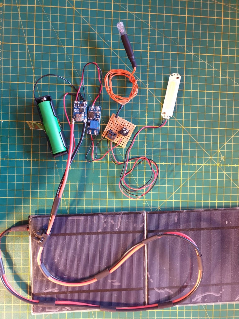
Step 1: Bill of Material
If you have already done some electronics projects you might already have all of the things you need to build this project!
Tools:
- Soldering Iron and solder
- Multimeter
- Wirecutter
- Basic electronics tools like a desoldering pump, screwdriver, etc.
Materials:
- 2x 2.5W, 5V solar panels
- 1x TP5456 charging circuit
- 1x MT3608 boost converter
- 1x 1w; 12V COB LED
- 1x 18650 Li-ion battery
- 1x 18650 battery holder
- 1x Prototyping PCB board (about 5x5cm)
- 1x electronics inclusion (mine is 88x88mm, got it from the local hardware store)
- 1x Photoresistor (I used an LDR 5537)
- 1x 1k Resistor (1000 Ohm)
- 1x 50k Potentiometer (50000 Ohm)
- 1x BC 547 transistor
- Wires (I used 14AWG wire to connect the solar panels and 0,5mm^2 wire for the rest)
So once you gathered your supplies, you are ready for the next step!
Step 2: Prepare Your Solar Panels:


In this design, we aim for a maximum charging amperage of 1000mA with 5V. (1A is the max. current of the TP4056)
Therefore you have to connect the two panels in parallel. So basically you just solder both plus and minus poles together.
Before doing this, I mechanically mounted the panels together with a piece of red electrical tape.
In order to connect the panels to the TP4056 input, you will need to leave some wire. I left about 80cm of wire and connected the two wires with some heat-shrink tubing every few centimeters.
Step 3: Prepare the Charging Circuit:


In the first step, you will prepare the TP5456 so you can start charging.
Why the TP5456?
So the TP5456 is a very good charging circuit for a single cell. It comes with some protective circuitry and will work for this project. Moreover, it is very cheap!
Just solder the plus pole of the solar panels to the positive input (IN+) and vice versa with the negative pole (solder the negative pole of the solar panels to the negative input [IN-]).
This will start powering the chip if the solar panels produce power. You should see an LED on the TP5456 light up.
Next just solder the positive pole of the 18650 battery holder to the B+ pole and solder the negative pole to the B- pole.
That's it! On to the next step!
Step 4: Add the Boost Converter:


One little problem with the TP5456 is the output voltage. It only puts out 5V. Not too big of a deal, but we will need a boost converter to power a 12V LED.
A very cheap boost converter I used is the MT3608 boost converter. It can supply a voltage from 2V to 24V.
The process is very easy. Just solder the Out+ to VIN+ and the Out- to VIN-. I used the standard thin wires to connect the ports.
Once you did this, you should calibrate the boost converter. So get your multimeter and a small screwdriver. You will want to measure the output voltage of the MT3608. Then start turning the potentiometer until you reach your desired voltage. Once you reached this voltage you are finished with this step.
Step 5: Prepare the Twilight Switch:


This is probably the part you have to be the most tech-savvy. So it is the most fun! :D
Here we will build our twilight switch. Basically, it is a transistor (electronic switch) witch will switch on or off depending on the brightness at the LDR (Light Dependent Resistor).
To start we will have to prepare the LDR. It will be placed outside so we will have to protect it from the environment.
To prepare the LDR I soldered extension wires to the two pins of the LDR. Afterwards I placed a small plastic tube over the LDR and filled the opening with some silicone glue. Just to hold it all together and tidy it up a bit I placed some heat shrink tubing over the end.
Now on to soldering the pcb! The schematic is next to the other pictures on top. It is relatively simple to follow, but if you have any questions feel free to ask in the comments.
After you build your twilight switch you can go on the next step!
Step 6: Preparing You COB LED:

This is one of the easiest parts! Just solder wires (I used 0.5mm^2) in your desired length to the plus and minus pads.
Since I mounted the lamp outside I coated the solder joints with electronics silicone to prevent corrosion.
Step 7: Finishing the Build:


At this point, you should have build everything you should need.
Now I would recommend putting in the battery and testing the whole setup. Before closing everything up you need to calibrate the twilight switch. First, put the LDR under the lighting conditions you want it to switch at and carefully turn the 50k potentiometer until the LED turns on. That's it!
Theoretically, the lamp should turn on if the twilight switch is removed from all light sources.
Afterwards put the whole contraption into your housing (mine was 88x88mm and about 70mm in height). Since mine will be placed outside I added a pack of silica gel to the housing. It just is to get rid of any excess moisture.
Once everything is placed in the housing you can close it up. Now it is ready to install!
Step 8: Installation:
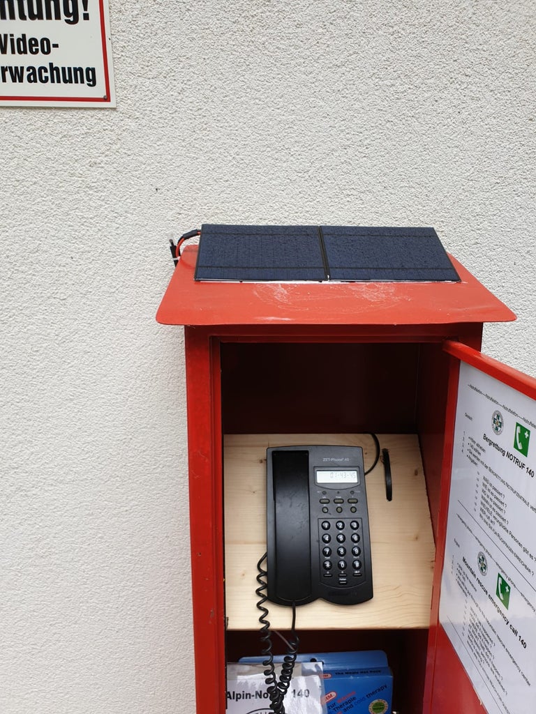


Depending on what you plan with your solar lamp, you have to install it differently.
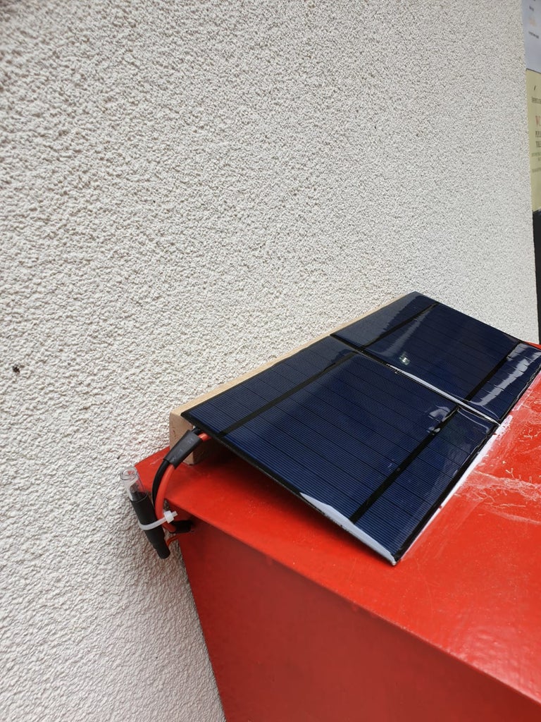
In my case, the lamp will be placed outside inside the housing of an emergency telephone in order to light in during the night. Therefore I mounted the solar panels on the top of the housing with construction adhesive.
For best results, the solar panels should be mounted with a 30° angle and preferably facing south.
When installing remember that the photoresistor has to be outside! Otherwise, it won't be triggered by sunlight.


Step 9: You Did It!
If you have followed through with this instructable until now, you should have a cool solar-powered LED lamp which is really bright.
If you have any questions left, just ask me!
Finally, I hope you had great fun with this electronics project! If you did please share it and post your results!


