

Introduction: Dangerous Lashes


Flesh-like silicone tube pierced by 28 dress pins becomes a mesmerizing display of dangerous lashes.
The gear shafts and the box housing them are all held together by sewing.
Step 1: Materials and Tools

MATERIALS
- Tube of silicone (see here)
- Dressmakers pins
- String
- Acrylic glass (3 mm thick)
- Stepper motor (28byj 48)
- Sparkfun's EasyDriver Stepper Motor Driver
- An Arduino
- Breadboard, jumper wires
- Bolts to fix motor in place
TOOLS
- Sewing needle
- Snips for cutting thread
- Computer/Software
- Lasercutter
Step 2: Model Gears and Box


I looked up the dimensions of the motor on the datasheet (http://robocraft.ru/files/datasheet/28BYJ-48.pdf) and used Fusion360 to build a sketch of the parts that I wanted. I also used a Fusion360 script to create the gears. But then I projected the gear body into the sketch and exported the sketch as a DXF. I opened the DXF file in Illustrator in order to separate the shapes into the parts I wanted to cut. The Illustrator SVG file is attached to the next step.
Step 3: Lasercut Gears and Box


Open the attached SVG file and cut the parts from 3mm thick clear acrylic. I cut mine using the following settings on an Epilog 120 Watt lasercutter. All lines are cut lines, except the thick circle on one of the gears. This is so that the thread from sewing the gear shaft together does not stick above the surface.
CUTTING:
power: 90
speed: 20
hz: 5000
ENGRAVING:
power: 60
speed: 30
dip: 600
Attachments

Step 4: Check Tollerances


Once your parts have cut, the following tolerances are important to check:
- does the gear with the engraved circle fit on the shaft of the stepper motor?
- does the silicone tube fit snug inside the hole cut for it?
- does everything stack together?
Step 5: Cleanup Parts


The small 1.5mm diameter holes that will be used for sewing the parts together often get stuck back together. Right after lasercutting is a good time to check these and clear out any material using a needle or other pointy object.
Step 6: Sand Surfaces


I chose to sand down the top visible surfaces of the box. First using course sandpaper and then a finer one.
Step 7: Sew Together 1


Once your parts are sanded, clean and the sewing holes are free, things are ready to get sewn together.
Start by sewing the shaft of the motor-less gear which gets sandwiched on either side of the rectangle with two holes (see photos). Thread the needle with a 1m long piece of thread. Begin sewing from the underside and stitch around until you are back at the beginning. Continue stitching to fill all the spaces between the holes and tie a double knot between the two ends.
Step 8: Sew Together 2


Sew the second gear that sits on top of the stepper motor shaft. The stitches and knot on the underside should disappear into the grove of the engraving.
Step 9: Fix Motor in Place


Before sewing the box together, use two screws with nuts to keep the motor in place. This is the flimsiest part of the design and I would love suggestions on how to solve this in a more interesting way.
Step 10: Sew Together 3


Sew the box together using a really long (3 meter) piece of thread. Pull each stitch tight. This might take a while.
Step 11: Finished Box With Gears


Here are some photos of the assembled box held up to the light.
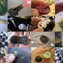
Step 12: Create Lashes From Pins and Silicone


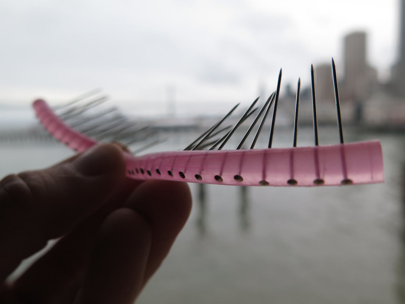

To create the pin lashes in silicone, insert them one by one. Make sure they are evenly spaced, parallel and go through the center of the tube. I used 28 pins along 13.5 cm of silicone tube.
Step 13: Insert Silicone Into Holes


Insert the ends of the silicone tube into the holes on the top of each gear. Twist the silicone to insure it goes in at least 1 cm deep for good grip.
Step 14: Build Circuit


Assemble the circuit following the diagram in this step. Bellow are links to the driver board and motor datasheet that might also be useful.
EasyDriver - Stepper Motor Driver >> https://www.sparkfun.com/products/12779
28byj 48 stepper motor datasheet >> http://robocraft.ru/files/datasheet/28BYJ-48.pdf
Step 15: Program Arduino to Control Stepper Motor


The movement seen in the video is made using the following code example:
Upload it to your Arduino and then open the Serial Terminal. You should receive the following prompt asking you to enter commands:
Begin motor control
Enter number for control option: 1. Turn at default microstep mode. 2. Reverse direction at default microstep mode. 3. Turn at 1/8th microstep mode. 4. Step forward and reverse directions.
To make the motor run continuously, I simply copied the following line of code into the main part of the loop so that it will get called continuously:
StepForwardDefault();
Step 16: Enjoy!


Participated in the
Full Spectrum Laser Contest 2016

Participated in the
Make a Box Contest

![Tim's Mechanical Spider Leg [LU9685-20CU]](https://content.instructables.com/FFB/5R4I/LVKZ6G6R/FFB5R4ILVKZ6G6R.png?auto=webp&crop=1.2%3A1&frame=1&width=306)


