

Introduction: Fix Cloned Arduino NANO CNC Shield


![Tim's Mechanical Spider Leg [LU9685-20CU]](https://content.instructables.com/FFB/5R4I/LVKZ6G6R/FFB5R4ILVKZ6G6R.png?auto=webp&crop=1%3A1&frame=1&width=130)


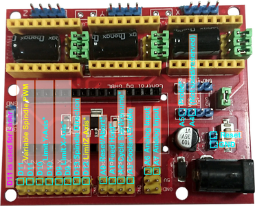
Modifying Clone Keyes CNC Shield.
On the web are Chinese cloned Keyes CNC Shields for the Arduino NANO.
They are cheep and good value. BUT.
If you want to set Micro Stepping as they are, you can't.
Who ever cloned/made this shield made a mistake and put the pins that should go to Vcc, to GND.
As the pins that set the Micro Step Mode are already pulled down to GND internally as default, and to change there state, they need pulling up to Vcc.
Step 1: Ways to Identify a Cloned Arduino NANO CNC Shield


1. The original Keyes Nano CNC Shield has a dark solder mask. (it looks blackish)
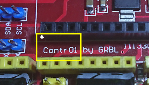
2. there are some print errors. Pins D9 and D10 are incorrectly identified. Control is spelt Contr01.
3. Look at the circuit track and see if the pins are connected to GND.
Step 2: Isolating Pins Top Side


The first step to put things right, is to isolate the pins from the GND rail.
This needs doing in Eight places.
First Two are on the top side.
I found, warming the header pins, made it easier to slide off the plastic supports.
Step 3: Isolating Pins Bottom Side


The next Six are underneath.
Step 4: Check That the Pins Have Been Isolated

After isolating the pins, check that they Are Isolated, using a circuit tester.
Check that they are no longer connected to ground.
Step 5: Connect Broken Ground Track

Isolating the pins from the GND track has separated the GND track and need reconnecting in two places.
Solder two pieces of tined copper wire in the place shown.
Step 6: Connecting Pins to Vcc


Now the isolated pins need connecting to the Vcc circuit.
Luckily there are pins connected to this circuit close by to the isolated pins.
Using tined copper wire make solder bridges to these pins as shown.
Be sure to keep the tined wire away from the track that runs under the bridge.
Step 7: All Finished

That's it.
The Micro-Step jumper Header Pins should now work as they should.
Step 8: GRBL Code

I write my own code when using this board, BUT.
As pointed out by FrancescP2 (in comments), If you are going to use gbrl firmware some changes to the code need making.
When you download the gbrl-master and unzip the file, in the folder you will find a folder called grbl, inside that folder you find a folder called cpu_map, inside that folder you will find 2 files, cpu_map_atmega328p.h and cpu_map_atmega2560.h.
As this shield is for the Arduino NANO, the file that needs changing is: cpu_map_atmega328p.h.
Open the file and you should see as shown (or similar) in the screenshot.
There are 2 ways to do this:
1. Only use cloned shield. If you don't intend to use a shield that is configured correctly.
Using screenshot as reference:
Line 39, change 2 to 5.
Line 40, change 3 to 6.
Line 41, change 4 to 7.
Line 47, change 5 to 2.
Line 48, change 6 to 3.
Line 49, change 7 to 4.
2. If you want to be able to quickly change from one type of shield to the other. (as shown by FrancescP2)
I will do this higher line numbers first so original line numbers (screenshot) I reference stay same for a time.
Lines 47,48 & 49 need replacing with:
#ifdef KEYS_CLONE
#define X_DIRECTION_BIT   2  // CLONE NANO Digital Pin 2
#define Y_DIRECTION_BIT   3  // CLONE NANO Digital Pin 3
#define Z_DIRECTION_BIT   4  // CLONE NANO Digital Pin 4
#else
#define X_DIRECTION_BIT   5  // Uno Digital Pin 5
#define Y_DIRECTION_BIT   6  // Uno Digital Pin 6
#define Z_DIRECTION_BIT   7  // Uno Digital Pin 7
#endif // KEYS_CLONE
Lines 39, 40 & 41need replacing with:
#ifdef KEYS_CLONE
#define X_STEP_BIT      5  // CLONE NANO Digital Pin 5
#define Y_STEP_BIT      6  // CLONE NANO Digital Pin 6
#define Z_STEP_BIT      7  // CLONE NANO Digital Pin 7
#else
#define X_STEP_BIT      2  // Uno Digital Pin 2
#define Y_STEP_BIT      3  // Uno Digital Pin 3
#define Z_STEP_BIT      4  // Uno Digital Pin 4
#endif // KEYS_CLONE
After line 30 insert a variable that can be changed to decide which shied is used?
#define GRBL_PLATFORM "Atmega328p"
#define KEYS_CLONE true
Changing the value of KEYS_CLONE:
true = using clone
false = using correct shield.
(FrancescP2 has given a link to a file he has alterd)
Step 9: Some Pin Changes in Grbl
If using the latest version of grbl, check there web site for some pin changes.
Step 10: Take a Photo of Your Work
Lets see how many "I Made It"s on this little instruction we can get.
I am sure there are a lot of these modules sold on the net.
- Sign up (If you haven't).
- Take a photo of your work.
- Click the I Made It button.
- Add your photo.
- Click Post.

Participated in the
1 Hour Challenge

![Tim's Mechanical Spider Leg [LU9685-20CU]](https://content.instructables.com/FFB/5R4I/LVKZ6G6R/FFB5R4ILVKZ6G6R.png?auto=webp&crop=1.2%3A1&frame=1&width=306)


