

Introduction: Go Further With Arduino Mega 2560 Starter Kits


Elegoo sent me freely a Mega R3 starter kit.
This starter kit contains a lot of equipments and is a good one to discover microprocessor and electronic thanks to the provided tutorial.
Unlike most of other starter kits, this does not contain a Aruino UNO but a Arduino Mega2560.
This instructable aims to show how to go further and take advantage of the Mega2560.
Supplies
Step 1: Arduino Mega Vs Uno
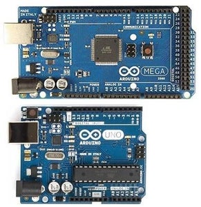
At the first look you can see the main difference between Mega and Uno.
Mega has a lot of more possible connexions, that means it is possible to connect much more sensors at a time.
- 54 digital GPIO vs 14 - (15 PWM vs 6)
- 16 analog GPIO vs 6
Mega has also much more memory, that means it will be able to run much more complex code
- 256 kB flach memory vs 32
- 8 kB SRAM memory vs 2
- 4 kB EEPROM memory vs 1
Due to the Microchip (Atmega2560 vs Atmega328) there are other differences that are not less obvious but could be crucial to deal simultaneously with different kind of sensors and complex code.
4 USARTs vs 1
6 interrupts GPIO vs 2
6 timers vs 3
Step 2: Take Advantage of the Atmega2560
It is easy to understand that the 14 GPIO of Uno are a limit easy to reach when we add equipments (for instance the LCD1602 alone requires 6 of them).
Conversely the 54 GPIO of the Atmega2560 will probably never limitate your development.
It is the same with the memory. 32kB of Flash is often to short when we need complex libraries, and 2kB of SRAM a huge constraint if we need variable arrays.
With respectively 8 and 4 times more memory the Atmega2560 move a lot back the memory constraint.
The only one Uno UART is difficult to use as a serial link with other equipment as it is also used for the USB connection with the computer for debugging.
With the Atmega2560, we can dedicate the Serial0 for debug and use Serial1, 2 or 3 for connecting to sensors or other microcontrollers.
The Arduino code is structured in two parts. The setup() that initializes the program and the loop() that runs permanently and synchronously.
When code complexity increases, it becomes necessary to support asynchronous events and forget delay() function usage.
The 6 Atmega2560 timers and 6 interrupt GPIO improves drastically the possibility to deal with asynchronous events
You already learned the basics with kit tutorials and want to go further with it, I wrote this instructable to help beginners to write efficiently more complex codes.
Step 3: Let's Deal With Asynchronous Events

Arduino program structure is simple:
- void setup() {to set the environment at the startup}
- void loop() { loop that will run permanently }
It's up to us to do all we need inside this loop. With the kit tutorials we learned mainly to deal with sensors and actuators once at a time. If we needed to slowdown the loop, we had to add a delay() instruction inside the loop.
But if we want our code to be able to deal simultaneous and independently with sensors and actuators we need to think differently.
Let's illustrate the delay limitation with the simple example above.
We want to read and print the sensor1 measurement on the serial monitor and to be able to stop the printing according to the sensors reading.
If we use delay() instruction to slowdown the printing, we will not be able to read the sensor2 value during the delay duration and will miss the stop requirements.
Step 4: Firstly Replace Delay() by Testing Millis()

When we need to do something regularly it is easy to replace the delay() instruction by a time testing inside the loop. Doing so we will maximize the possibility to catch asynchronous events.
Notice that time provided by millis() must stored in an unsigned long which requires 4 bytes.
The Arduino Mega with the 8KB autorizes to store huge number of time.
Above an illustration.
Step 5: Secondly Replace Testing GPIOs by Interrupts


Instead of permanently testing a GPIO values inside the loop, it is possible to use microcontroller interruptions to keep informed of GPIO values changes.
To do so we have to:
- define a function (Sensor2Interrupt()) that will be called each time the event we expect appears.
- define the trigger of the event with attachInterrupt instruction ()
- the GPIO to monitor (must be part of the shortlist of interruptible GPIO)
- the function to call
- the change to monitor (for instance going from LOW to HIGH)
Notice that Arduino Mega provides 6 interruptible GPIOs instead of 2 for the UNO.
Step 6: A Word About Microcontrollers Timers

Even if I will not enter in details in microcontrollers timers, it is important to keep in mind their existences.
Timers (6 for the Arduino Mega, 3 for the UNO) can be used to automatically and regularly (based on duration) trigger some of your code. I use this timers for instance to control the DC motor speed.
It is rather complex and I will not go further. If you are interested you can read this well documented instructable.
In any case it is important to bear in mind these timers. They are used by a lot of libraries and can be the origin of integration conflicts. For instance PWM, tone(), servomotor library use timers.
Above the Timers and Pins relationship for the Arduino Mega
Step 7: Let's Go to the Practice

In this tutorial we will learn how to drive the 3 kinds of motors that are in the kit asynchronous and independently.
On top of that we will explore the clock DS13707 internals.
The scenario is:
- each motor can be started and stopped with a dedicated push button
- with the tilt ball we stop all the motors at a time and play sound
- each second the time is printed on the LCD
Parts list
- 1 x big breadboards
- 1 x little breadboards
- 1 x 5v DC power supply
- 1 x 5v DC motor
- 1 x SG90 servo motor
- 1 x 28BYj-48 stepper motor
- 1 x LCD1602 screen
- 1 x DS1307 RTC module
- 1 x ULN2003 stepper driver
- 1 x L293D module
- 1 x passive buzzer
- 1 x tilt ball switch
- 1 x 10K potentiometer
- 1 x 1K resistor
- wires
Step 8: Let's Chose the Arduino Mega Pins
This tutorial requires 22 GPIOs.
The trick is to determine early which Pin we will use. To do so we have to think to each component requirements
- do we need PWM ?
- do we need interrupt ?
- do we need I2C (or SPI or serial) communication ?
In our case
RTC:
needs I2C so Pin_20 and Pin_21 are required
needs an interrupt Pin - we don't need Serial3 so we can use Pin_19
Tilt ball needs an interrupt - we don't need Serial3 so we can use Pin_18
DC motor needs a PMW - we will not use timer4 so we can choose Pin_6
Buzzer needs a PMW - we will not use timer4 so we can choose Pin_7
There are no other specific requirements we will use Pins that have no specific characteristics and are not used by timers or communication.
Lets' choose
- Pin_22 to 27 for the LCD
- Pin_29 & 30 for the DC motor
- Pin_31 to 34 for the stepper motor
- Pin_35 for the servo motor
- Pin_36 to 38 for the push buttons
Step 9: Let's Connect All Together
For connecting each component we just have to follow the component tutorial and replace Pins number used in these tutorials by that we just choose.
We will use the little breadbord to connect the 3 push buttons.
Regarding power we will use exclusively the 5V provided by the power supply connected to the breadbord. Ther is no need to use Arduino 5V Pin.
The Arduino is powered through the USb connection
Step 10: Let's Zoom on the LCD and Clock


The RTC module provides the occasion to go deeper inside the interrupt mechanism and I2C protocol. In the tutorial 19 we can see that the RTC module has a Pin named SQW that is not used.
We will learn what can we do with this. Firstly let's read the DS1307 datasheet.
We can find:
- When enabled, the SQWE bit set to 1, the SQW/OUT pin outputs one of four square wave frequencies (1 Hz, 4 kHz, 8 kHz, 32 kHz).
- The SQW/OUT pin is open drain which requires an external pullup resistor
- DS1307 address map - at 07H there is the control register
- the bit number 4 of this control register enable/disable the output
- the bits 0 & 1 select one of the four the output cycles (1Hz, 4096Hz,8192Hz,32768Hz)
We will set up this feature. On top of the clock connections described in chapter 19, we will connect the SQW pin to the pin 19 of the Arduino.The datasheet the SQE pin requires an external pullup resistor. That why we have to add a 1K resistor between the signal and the +5v.
Now to enable 1Hz output we just have to 0b00010000 inside the control register. To do so we must use directly I2C instructions inside the setup.
- Wire.beginTransmission(0x68); // transmit to device 68 RTC address
- Wire.write(0x07); // DS control register to modify
- Wire.write(0b00010000); // set bit 4 SQWE to 1 to enable oscillator output
- Wire.endTransmission(); // stop transmitting
It is easy then to use the 1Hz interruption to display time on the LCD every seconds.
Above you can see the square signal captured by an oscilloscope and a scheme of the connections.
Step 11: Let's It See in Action
Here you can donwload the code ! - More comments inside the code


