

Introduction: Hacking the Lego Mindstorms RCX With an Arduino Part II: Fine Motor Control


Part I: https://www.instructables.com/id/Hacking-the-Lego-M...
Further to my previous Instructable about setting up the motors and sensors from an old RCX Mindstorms kit to be controlled by an Arduino, I learned that, in order to get a finer control over my motors, I would have to use a controller IC - the L293D. I ordered a couple of these which arrived quickly so I started playing about with them - this is what I ended up doing.
This is mainly about controlling the motors but I have also started playing with the sensors to see how to make the robot more autonomous - I will add this as a separate Instructable when I have finished trying everything out. There are a lot of tutorials on how to do this out there but this summarises all the construction and programming steps I took to get the nifty little robot in the video!
Step 1: Setting Up the L293D Motor Controllor IC

Disclaimer: This is my simplified understanding of how this chip works and may not be entirely technically correct!
Essentially this chip has two sides. Each side can control one d.c. motor. On the left there is the 'enable' pin, which controls the positive supply to the motor. There are also 2 'output' pins which attach to the motor. The two 'input' pins determine which direction the motor goes in.
So for example, if input1 = 0 and input2 = 1, the motor will turn one way. If input1 = 1 and input2 = 0, it will turn the other. If they are both the same (1 or 0), it won't turn at all.
I think that pin 8 can be used if you need a larger voltage across your motors than the 5V provided through the Arduino although I'm not entirely clear on how that works - I assume you just connect your supply up to that pin and the chip takes care of the rest, I haven't tried it yet.
So the idea is to connect each side up to three pins on the Arduino and control it through there.
Step 2: Connecting the Arduino and Some Test Code
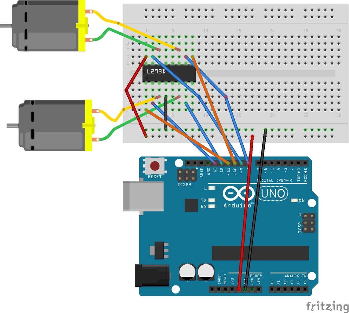
I connected everything up as shown in the diagram. I made sure that each 'enable' pin was connected to an analogue output pin on the Arduino (ones with wiggly lines next to them...). This was so that I could try to control the speed of the motor later on as well as the direction. I then ran some testing code to check that my motors were connected in appropriate directions:
int leftEnablePin = 11; //setting up the pins for the motors

int left1Pin = 13;

int left2Pin = 12;

int rightEnablePin = 10;

int right1Pin = 9;

int right2Pin = 8;


//setting pins as outputs
void setup() {

pinMode(left1Pin, OUTPUT);

pinMode(left2Pin, OUTPUT);

pinMode(leftEnablePin, OUTPUT);

pinMode(right1Pin, OUTPUT);

pinMode(right2Pin, OUTPUT);

pinMode(rightEnablePin, OUTPUT);

}


//Main running code

void loop(){

digitalWrite (leftEnablePin, HIGH);

digitalWrite (left1Pin, 0);

digitalWrite (left2Pin, 1);

digitalWrite (rightEnablePin, HIGH);

digitalWrite (right1Pin, 1);

digitalWrite (right2Pin, 0);

}
Because the motors will be sitting opposite each other, I would technically want them turning in opposite directions in order for them to both 'go forward'.
This all worked well and good. I spent a while messing around with the push button sensor in order to get it to reverse as well but more on that another time.
Step 3: Making the Programming Easier
I normally write very clunky code as I'm no programmer and just tend to write actions as I want them to happen. All this clever algorithm stuff is a little beyond me. However, I realised that, in order to save time later and make things generally easier, I could write functions for everything that I wanted to do.
I decided that I wanted it to go forward and backwards both fast and slow and turn right and left. That should pretty much cover everything that I could think of apart from more sophisticated turns and the like.
I have attached the sketch and copied the code below;
int leftEnablePin = 11; //setting up the pins for the motors
int left1Pin = 13;
int left2Pin = 12;
int rightEnablePin = 10;
int right1Pin = 9;
int right2Pin = 8;


int l_motorDirection = 0; //sets up variables for direction
int r_motorDirection = 1;


//setting pins as outputs

void setup() {
  pinMode(left1Pin, OUTPUT);
  pinMode(left2Pin, OUTPUT);
  pinMode(leftEnablePin, OUTPUT);
  pinMode(right1Pin, OUTPUT);
  pinMode(right2Pin, OUTPUT);
  pinMode(rightEnablePin, OUTPUT);

}

//Main section telling the robot what to do
void loop() {
  fast_forward();
  delay(1000);
  left();
  delay(500);
  slow_forward();
  delay(1000);
  left();
  delay(500);
  fast_forward();
  delay(1000);
  no_move();
  delay(2000);
  fast_backward();
  delay(500);
  right();
  delay(500);
  slow_backward();
  delay(1000);
  no_move();
  delay(2000);

}

//code to set up the command functions
void fast_forward(){
  analogWrite  (leftEnablePin, 255);
  digitalWrite (left1Pin, l_motorDirection);
  digitalWrite (left2Pin, !l_motorDirection);
  analogWrite  (rightEnablePin, 255);
  digitalWrite (right1Pin, r_motorDirection);
  digitalWrite (right2Pin, !r_motorDirection);
}
void slow_forward(){
  analogWrite  (leftEnablePin, 70);
  digitalWrite (left1Pin, l_motorDirection);
  digitalWrite (left2Pin, !l_motorDirection);
  analogWrite  (rightEnablePin, 70);
  digitalWrite (right1Pin, r_motorDirection);
  digitalWrite (right2Pin, !r_motorDirection);
}

void fast_backward(){
  analogWrite  (leftEnablePin, 255);
  digitalWrite (left1Pin, !l_motorDirection);
  digitalWrite (left2Pin, l_motorDirection);
  analogWrite  (rightEnablePin, 255);
  digitalWrite (right1Pin, !r_motorDirection);
  digitalWrite (right2Pin, r_motorDirection);
}

void slow_backward(){
  analogWrite  (leftEnablePin, 70);
  digitalWrite (left1Pin, !l_motorDirection);
  digitalWrite (left2Pin, l_motorDirection);
  analogWrite  (rightEnablePin, 70);
  digitalWrite (right1Pin, !r_motorDirection);
  digitalWrite (right2Pin, r_motorDirection);
}

void left(){
  digitalWrite (leftEnablePin, HIGH);
  digitalWrite (left1Pin, !l_motorDirection);
  digitalWrite (left2Pin, l_motorDirection);
  digitalWrite (rightEnablePin, HIGH);
  digitalWrite (right1Pin, r_motorDirection);
  digitalWrite (right2Pin, !r_motorDirection);

}

void right(){
  digitalWrite (leftEnablePin, HIGH);
  digitalWrite (left1Pin, l_motorDirection);
  digitalWrite (left2Pin, !l_motorDirection);
  digitalWrite (rightEnablePin, HIGH);
  digitalWrite (right1Pin, !r_motorDirection);
  digitalWrite (right2Pin, r_motorDirection);
}
 void no_move(){
  digitalWrite (leftEnablePin, LOW);
  digitalWrite (left1Pin, LOW);
  digitalWrite (left2Pin, LOW);
  digitalWrite (rightEnablePin, LOW);
  digitalWrite (right1Pin, LOW);
  digitalWrite (right2Pin, LOW);
 }
I have set the 'motorDirection' as a variable so that I can access and alter it when reading from sensors, buttons etc.
I had to use the odd 'no_move' instead of 'stop' as Arduino already has stop as a code command.
From a bit of trial and error I discovered that 500ms is long enough during a turn for it to go 90 degrees.
The speed control involves analogWrite instead of digitalWrite and I have 255 as the maximum value with 70 for my slow value.

Step 4: In Conclusion

I was fairly happy with this turning out well and I can now program my robot to do a series of pre-planned moves. I used high tech rubber bands and double sided sticky tape to get everything onto my lego chassis and gave up trying to use 4 wheels, ending up with just a pole at the front.
Next step is to add in some sensor equipment and see how autonomous I can make it. For now I would like to avoid using the Arduino sensors (ultrasonic distance, light, IR etc.) and just stick to the LEGO ones to see how far I can take it.
If any programmers have a better idea on the coding then please let me know!


