

Introduction: How to Use/configure a Bluetooth Module


![Writing Your Hand Written Text With a Plotter [G-Code]](https://content.instructables.com/FTY/0K4F/LW82OIZV/FTY0K4FLW82OIZV.png?auto=webp&crop=1%3A1&frame=1&width=130)
![Tim's Mechanical Spider Leg [LU9685-20CU]](https://content.instructables.com/FFB/5R4I/LVKZ6G6R/FFB5R4ILVKZ6G6R.png?auto=webp&crop=1%3A1&frame=1&width=130)

This is about using Bluetooth Modules.
- The cheep ones from eBay.
- There two main types, 4 pin (HC-06) and 6 pin (HC-05).
Please Note!
- When I say HC-05 and HC-06 I am refiring to the Module name, not the Bluetooth chip on the module.
As I may do projects that use a Bluetooth Module I thought I would this Instructable so I can refer to it from other Instructables. (save repeating things haha.)
- It could be something others could refer to who also use a Bluetooth Module in the projects.
- I hope it gives a bit more understanding, using them.
Not all Manufactures use the same AT commands to set the parameters of there Bluetooth Microprocessors.
- This Instructable will go over the basics to change the speed and Name of the two main types of Bluetooth Modules.
I would say that the majority of Bluetooth Modules are 3.3 volt devices.
- Although most say 5 volt compatible. this is only refiring to the power.
- I will also show details how I prefer to connect these modules to a microcontroller with 5 volt GPIO pins.
Assumptions:
- I assume that you know about Arduino code.
- I assume you know how to use the Arduino IDE.
Supplies


A Bluetooth Module.
- HC-05 or HC-06
I prefer a USB to UART Module to set my Bluetooth Modules.
- An Arduino Nano will do the same, with or without code installed.
If using a USB to UART Module:
- A small adapter will need to be made.
If using an Arduino other components will be required:
- A solderless Breadboard, to connect things together.
- A Logic Voltage converter.
- Cable to connect things.
If your computer does not have Bluetooth capability:
- A Bluetooth Dongle to give your computer Bluetooth connection capability.
To communicate with the Bluetooth device, a Serial monitor/terminal will be required.
- I use my own Serial Monitor: Tim's PC Applications: Tim's Serial Monitor (tims-pc-applications.blogspot.com)
- The Arduino IDE Serial Monitor can be used.
- Any software that can communicate with the COM Ports on the PC will do.
Step 1: Communication


Simplified Definitions:
UART (USART)
- Universal Asynchronous Receiver/Transmitter (Universal Synchronous/Asynchronous Receiver/Transmitter)
- Programming/Protocol that controls a computer’s interface to its attached serial devices.
- Could be either I will just refer to UART.
USB
- Universal Serial Bus
- Generally this just refers to the type of connection (Its the Serial part I will be refiring to when I say USB Serial)
USB Serial
- Another protocol used to transfer data along a cable.
- Serial can have many formats, but in this case you just need to know USB Serial uses a different protocol to UART.
Arduino Pins 0 and 1 (RX and TX)
- These pins are connected to the Hard UART of the Microcontroller. (They are Arduino Pin numbers not chip numbers)
Arduino
- An architecture that by the means of Libraries, Shields/Boards and an IDE (Integrated Development Environment), simplifies the way people can program and use Microcontrollers.
To configure a Bluetooth Module requires communicating with the device using "AT" Commands.
- Not all manufacturers use the same commands, they use similar commands with slight differences.
- I have seen many versions of Bluetooth Modules on the market, 4 pin, 6 pin, HC-05, HC-06 and HC-10.
- So downloading the right data sheet and manual is essential.
- This information refers to the two above. (If I get any of the other types of modules I will update this to suit)
Bluetooth Modules have 2 main communication modes:
- 1. Data mode. Where data is just sent and received.
- 2. Command mode. In Command mode, "AT" commands can be sent to the device, to make it do tasks.
The HC-05 6 pin Module needs the CMD pin High or Low to set the mode. (The breakout board usually has a button)
The HC-06 4 pin module automatically changes to Data Mode when connected to a Paired Device and to Command Mode when not connected to a Paired Device.
I use a USB to UART Modules to configure my Bluetooth Modules, I like it because it has jumper to select Logic Level Voltage. Which means I can connect the Bluetooth Module direct.
- If you don't have one of these, you could use an Arduino Nano instead.
A USB Serial to UART is required required because in most we communicate to the modules via a Serial Monitor/Terminal to the USB Serial Port.

Step 2: Warning 3.3 Volts

Not all Bluetooth Modules can accept a 5 volt data line.
Although a Bluetooth Module may be advertised as 5 volt compatible, this may ONLY refer to the Power Input.
The Data connections (RXD and TXD) may only be 3.3 volt.
Putting 5 volt on the RXD pin will Destroy that Input Pin on the UART chip.
Step 3: Logic Level Convertion


To use a Bluetooth Module with a Microcontroller that has 5 volts logic such as the Arduino UNO, some form of voltage conversion is required.
You can use resistors to make voltage dividers on each data line, but I prefer to use MOFETs.
You can buy a Logic Level Converter on eBay.
Sometimes on a project I will make my own.
- I have done a fritzing of the type I make when making a project.
- The fritzing shows a typical circuit for a Logic Level Converter using MOSFETs

Step 4: Connecting the Bluetooth Module to a Microcontroller


There are several types of Microcontrollers on the market for building projects.
- I will refire to two types of Microcontroller: One that does not have USB Serial and One that does have USB Serial.
- I will use the Arduino Nano and the Arduino Leonardo for reference.
In either case The Bluetooth Module needs to be connected to a UART Port on the Microcontroller.
- It can be a hard coded port, this means that the Microcontroller has a UART device built into it. The pins used will be pre-defined. (More modern Microcontrollers may have more than one UART or give you a choice of which pins to use)
- It can be a soft coded port, this means that you have written code and uploaded the code to the Microcontroller to handle UART commands on pins of your choice.
Most Arduino Modules (Boards) like the Nano and Leonardo have a USB port to use the Serial Communication.
- The Arduino Nano uses an ATmega328, this does not have a USB Port, there is a separate chip on the Arduino Nano Module (Board) that converts USB Serial to UART.
- The Arduino Leonardo uses an ATmega32u4, this does have USB Port built in. (This is why the Leonardo can be use as HID).
Looking at the flow charts I have made you can see how the two types communicate and how the Arduino TX and RX pins are connected.
- The reason I have shown the flow charts is you can see that when using a microcontroller that does not have inbuilt USB Serial, there will be an extra chip installed on the board to convert the USB Serial to UART and it will be using the UART that Arduino uses for TX and RX pins.
- This means you cannot use the USB and the TX and RX pins at the same time on this type of board.
- However if you should want to use both the USB and a Bluetooth Module, you can use Soft Serial using code to make a UART Port on two other pins of your choice.
- Another reason to show the flow chart is you can see that with a NANO, it could be possible to communicate to a Bluetooth device on the NANO TX and RX pins, providing there is no code and the ATmega328 is not using its UART pins. (Not recommended if you are new to this)
Speed Limitations:
- Hard Serial (UART) is limited to the Specification of the the Microcontroller.
- Soft Serial (Code made to emulate a UART Port) Arduino limit (The microcontrollers I am using as reference) is usually 57600.
I have simplified things with the Arduino Leonardo, there is other things that happen with the USB when programming it.
- I wanted to use it as an example, as there are newer cheaper microcontrollers now like the ESP series.
Step 5: Using Soft Serial on an Arduino


Lets Use Soft Serial, as you should be able to apply this to all Arduino Boards.
- With Soft Serial you can chose which pins you want to use to connect to the Bluetooth Module.
- Doing it this way will require code uploading to your Arduino to manage the UART emulation.
Note the use of a Logic Level converter.
- The data pins of the Arduino are 5 volt logic.
- The data pins of the Bluetooth Module are 3.3 volt logic.
I have attached the Sketch it looks like this:
#include <SoftwareSerial.h>

#define BT_RX A2					/*	Bluetooth RX to Arduino TX.	*/
#define BT_TX A3					/*	Bluetooth TX to Arduino RX.	*/
SoftwareSerial BTS(BT_TX, BT_RX);	/*	(Arduino RX, Arduino TX )	*/

void setup(){

	/*	Open serial communications for the USB
		9600, 38400*, 115200 Set this to what you prefire.
		The Serial Monitor needs to be set to the same.
	*/
	Serial.begin(38400);

	Serial.println("Ready for configuration...");

	/*
		Open serial communications for the Bluetooth Module.
		9600 default, 38400

	*/
	BTS.begin(38400);
}


char a = 0;
char b = 0;
void loop(){

	BTS.listen();
	if (BTS.available()) {
		a = BTS.read();
		Serial.print(a);
	}


	if (Serial.available()) {
		b = Serial.read();
		Serial.print(b);
		BTS.print(b);
	}
}
What this does is:
- Checks to see if any data has been received by the Bluetooth Module.
- If data is available from the Bluetooth Module it reads the data character by character, each time sending the character on to the Serial Port (USB).
- Checks to see if any data has been received by the Serial Port (USB).
- If data is available from the Serial Port (USB) it reads the data character by character, each time sending the character on to the Bluetooth Module.
The Bluetooth devices UART speed are set to 9600 by default in Data Mode.
- Command Mode speed may be different to Data Mode speed.
- Not all Bluetooth modules have the same Command Mode speed.
- HC-05 May have a Command Mode speed of 9600
- HC-06 may have a Command Mode speed of 38400 (Depends on how Command Mode was set.)
So, using the sketch above in data mode, may need the BTS.begin(38400) changing to BTS.begin(9600).
- Or vice versa.
- Or if you have changed the UART Data Mode speed, to what ever you have changed it to.
Remember there is a data mode speed limit for using Soft Serial with Arduino, it's 57600
I have done two sketches, they both do the same thing.
- One is without an LCD
- One is with an LCD
- I have an Arduino Nano setup with an LCD for doing small examples.
- I did one with an LCD to remind me what I have set the Serial Speeds to.
Remember an Arduino Sketch needs to be placed in a folder of the same name without the extension ".ino".
Step 6: Using a USB to UART Module


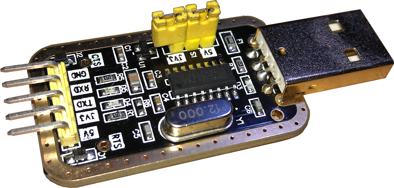
Using a USB to UART Module to make changes to the Bluetooth Module is much easier.
- I use one that has the CH340 chip.
- It is the same chip that is used on the Arduino Nano clones.
The CH340 can be powered with 3.3 volts or 5 volts.
- The module I have has a jumper to select which voltage to power it with.
- If it is powered by 3.3 volts the IO Pins will be 3.3 volts logic.
- If it is powered by 5 volts the IO Pins will be 5 volts logic.
With it set to 3.3 volts, all I need is an adapter to to connect it to the Bluetooth Module.
- I just made it out of 2 Female Pin Headers and a piece of wire
- See the circuit to see the connections.
Attachments
Step 7: Changing the Settings on the Bluetooth Module


Hopefully you now know how to connect to the Bluetooth Module using one of two methods.
- USB to UART Module
- Arduino acting as a USB to UART device.
When changing the settings of your Bluetooth Module.
- It does not matter which way you have connected the Module to your Computer.
- It does not matter which Serial communications Application you use.
- The Serial Application will use the the USB COM port you have connected the Arduino or USB to UART module to.
- If using the USB to UART: The speed in the Application should be set to the speed of the Bluetooth Module.
- If using the Arduino: The speed in the Application should be set to the speed set for "Serial" in the code.
- If using the Arduino: The speed of the of the Bluetooth Module should be set in the code for "Soft Serial".
There are three things I change on a Bluetooth Module.
- The Name. This is so when I Pair my PC with a Bluetooth Module, I know which one to choose .
- The Password. I make them all the same, 1234. makes it easy to remember. If it is for special project used in the open world I may make it complicated.
- The UART Speed. usually I have it as fast as the Microcontroller and my PC will handle if HARD WIRED. But for general norm, I set it to 115200 when connecting to the Microcontrollers built in UART and 57600 when using Soft Serial on an Arduino.
Commands.
Bluetooth modules use AT commands.
- AT commands are used to control a Bluetooth Module and make changes to the way they work.
- Sending AT on its own, should get an OK reply. This is the basic command and just checks to see if all is OK and we are connected in Command Mode and can communicate with each other.
- To send actual commands we send AT+ followed by the command.
- Some Commands will also be followed by text/value/parameters.
- All commands are a text string, so if you get advanced and send commands in your code, it is all sent as a string.
- All commands should be followed with a "Carriage Return" (\r) and "New Line" (\n)
- Be sure to set \r\n in your Serial Application.
As there are two types of Bluetooth Modules we are covering here I will split them into the next two Steps:
- Step 8 will deal with HC-05 six pin.
- Step 9 will deal with HC-06 four pin.
There are some differences between the two types of module due to the improvement of technology and the way Bluetooth chips have progressed.
- There are pros and cons to using each type of module.
If you have both types of Bluetooth Modules it can get confusing.
- Some times we will use an "=", sometimes we won't.
- Some times we will use a "?", sometimes we won't.
- Some times we will use "Values", sometimes we use "Codes".
- Some times we get an "=", sometimes we don't.
- Some times we get an "OK", sometimes we don't.
A Little Tip:
When I change something from the default on a Bluetooth Module I write it on a small piece of paper and slide it under the shrink-Wrap on the back of the Bluetooth module.
- This way I know the settings next time I use it.
Step 8: HC-05 [Six Pin] Bluetooth Module
![HC-05 [Six Pin] Bluetooth Module](https://content.instructables.com/FM4/NYLE/LNIWTJNB/FM4NYLELNIWTJNB.png?auto=webp&fit=bounds&frame=1&width=1024auto=webp&frame=1&height=300)
NAME
- The default name will be something like: Who ever made the Module.
- This does not matter, we are going to change it.
PASWORD
- The Password will probably be: 000000
- This does not matter, we are going to change it.
UART
- The HC-05 default speed settings are: 9600
- This is for both In Data Mode and Command Mode.
- When we change the speed on a HC-05 the speed we set will be for both the Data Mode and Command Mode.
- To communicate in Command Mode we hold the CMD pin LOW. This is why HC-05 Has six pins, one of the pins is the CMD (Command) pin.
- The HC-06 also unusually have a button, with the button held down sends the CMD pin LOW.
- However there is a special command mode.
- The special Command Mode is in case you have forgotten all the settings.
- If you hold the swich down while powering up, will put it into the special command mode and the speed will be 38400. (Always when you do it this way, no matter what was set.)
LED
- When Powered ON in no particular Mode. The LED usually blinks at a fast rate.
- When Powered ON in Command Mode. The LED usually blinks at a slow rate.
- When connected to a Paired Device. The LED usually blinks twice then is off for a short time, then repeats.
After Reading Step 7
Once you have connected to you Bluetooth Module with your Serial Application you are able to communicate with it.
Because we may not always know the settings of a HC-05.
- I prefer to to put it into the Special Command mode.
- Hold the button down while powering the Bluetooth Module.
- If you use an Arduino and become more familiar with the HC-05 you may want to add code to the Arduino to use a pin on the Arduino to set this pin HIGH or LOW.
Commands:
First we send AT
- We should receive OK
- If we was to send AT+ followed with a command, usually the reply would look similar to the command sent with the addition of some info.
NAME (Module Name)
Lets see what the current Name is:
- Send: AT+NAME?
- You should get a reply. For me I would get: +NAME:Tim's HC-05 followed by OK (You will get its current Name)
To change the Name we would use the same command but replace the "?" with "=" followed by the Name we want to change it to.
- Send: AT+NAME=Tim's BT5
- You should get a reply: OK
To check that the Name has changed.
- We send: AT+NAME? again.
- You should get a reply: +NAME:Tim's BT5 followed by OK
Obviously you will want to change it to a Name of your choice.
- Usually you can have up to 31 characters max (including spaces) in a Name.
PASSWORD
Lets see what the current Password is:
- Send: AT+PSWD?
- You should get a reply. For me I would revive: +PSWD: "1234" followed by OK (You will get its current Password)
To change the Password we would use the same command but replace the "?" with "=" followed by the Password we want to change it to. Also note the the Password is in quotes.
- Send: AT+PSWD="0000"
- You should get a reply: OK
To check that the Password has changed.
- We send: AT+PSWD? again.
- You should get a reply: +PIN:"0000" followed by OK
Obviously you will want to change it to a Password of your choice.
Usually you can have up to 16 characters max in a Password.
UART
With the HC-05 we change all the UART settings using a code from a chart: {Baud}, {Stop Bit Code}, {Parity Code}.
The codes are as follows:
Baud:
- 4800
- 9600 (default)
- 19200
- 38400
- 57600
- 115200
- 234000
- 460800
- 921600
- 1382400
Stop Bit Code:
- 0 = 1 bit (default)
- 1 = 2 bits
Parity Code:
- 0 = None (default)
- 1 = Odd parity
- 2 = Even Parity
NOTE!
When you change settings of the UART.
- You have to change the settings used to communicate with it. (If not in special Command Mode)
- If you are using an Arduino you will need to set the values in your code.
- If you are using a USB to UART the Serial Application settings need to match.
- This is another reason I like to use a USB to UART Module to change settings, it is easier.
Lets see what the current UART settings are:
- Send: AT+UART (Notice there is not a "?")
- You should get a reply. For me I would get: +UART:115200,0,0 followed by OK (If it is still set to the default you will get: +UART:9600,0,0)
To change the UART we would use the same command but with with "=" followed by the parameters we want to change it to.
- In general we do not change the Stop Bit or the Parity, we leave them set to 1 Stop Bit and No Parity.
- The code for 1 Stop Bit = 0.
- The code for No Parity = 0.
- The only thing we change is the Baud.
Lets say we want to set the Baud to 57600
- Send: AT+UART=57600,0,0 (Note that the speed is the actual speed, but the Stop Bit and Parity are code numbers)
- You should get a reply: OK
We have now changed the speed of the Bluetooth Module, so any communication setting that talk to the Bluetooth Module must be changed to that same speed.
To check that the speed has changed.
- If using an Arduino change your code to match.
- If using a USB to UART change the speed in the Serial Application.
- We send: AT+UART again.
- You should get a reply: +UART:57600,0,0 followed by OK
Obviously you will want to change it to a speed of your choice.
Step 9: HC-06 [Four Pin] Bluetooth Module
![HC-06 [Four Pin] Bluetooth Module](https://content.instructables.com/F8I/VWBK/LNKC29TV/F8IVWBKLNKC29TV.png?auto=webp&fit=bounds&frame=1&width=1024auto=webp&frame=1&height=300)
The HC-06 is a little cleverer than the HC-05, it changes form Data Mode to Command Mode automatically.
- Depending on whether it is connected to another Bluetooth Device determines if it is in Command mode or Data Mode
- If it is not connected to another Bluetooth Device it is in Command Mode. (Commands are sent via the UART)
- If it is connected to another Bluetooth Device it is in Data Mode. (Data is sent both ways between Module and Device)
Note!
- I find with the HC-06 when I have made changes, a re-boot of the module is a good thing to do.
NAME
- The default name will be something like: Who ever made the Module.
- This does not matter, we are going to change it.
PASWORD
- The Password will probably be: 1234
- This does not matter, we are going to change it.
BAUD
- The HC-06 default speed settings are: 9600
- This is for both In Data Mode and Command Mode.
- When we change the speed on a HC-06 the speed we set will be for both the Data Mode and Command Mode.
LED
- When Powered ON in Command Mode. The LED usually blinks at a slow rate.
- When connected to a Paired Device. The LED usually stays ON. (I have noticed with mine, If you connect then disconnect the LED will remain ON)
After Reading Step 7
Once you have connected to you Bluetooth Module with your Serial Application you are able to communicate with it.
Make sure there is no connection to the Bluetooth Module from another Paired Bluetooth Device.
- If another Paired Bluetooth Device (like your computer) is connected to it, it will automatically set its self to data mode.
- You don't have to un-Pair it from your PC, just do not connect via Bluetooth.
Commands:
First we send AT
- We should receive OK
- If we was to send AT+ followed with a command, usually the reply would look similar to the command sent with the addition of some info.
NAME
Lets see what the current Name is:
- Send: AT+NAME
- You should get a reply. For me I would get: +NAME=Tim's HC-06 (You will get its current Name)
To change the Name we would use the same command and immediately followed by the Name we want to change it to.
- Send: AT+NAMETim's BT6
- You should get a reply: +NAME=Tim's BT6 followed by: OK
To check that the Name has changed.
- We send: AT+NAME again.
- You should get a reply: +NAME=Tim's BT6
Obviously you will want to change it to a Name of your choice.
- Usually you can have up to 31 characters max (including spaces) in a Name.
PASSWORD
Lets see what the current Password is:
- Send: AT+PIN
- You should get a reply. For me I would revive: +PIN=1234 (You will get its current Password)
To change the Password we would use the same command and immediately followed by the Password we want to change it to.
- Send: AT+PIN0000
- You should get a reply: +PIN=0000 followed by OK
To check that the Password has changed.
- We send: AT+PIN again.
- You should get a reply: +PIN=0000
Obviously you will want to change it to a Password of your choice.
Usually you can have up to 16 characters max in a Password.
BAUD
With the HC-06 we change all the Baud settings using a code from a chart, we don't change the other UART setting we usually leave them as they are.
Baud Code = one of the following:
- 1 = 1200
- 2 = 2400
- 3 = 4800
- 4 = 9600
- 5 = 19200
- 6 = 38400
- 7 = 57600
- 8 = 115200
- 9 = 230400
NOTE!
When you change the Baud (Speed).
- You have to change the settings used to communicate with it.
- If you are using an Arduino you will need to set the values in your code.
- If you are using a USB to UART the Serial Application settings need to match.
- This is another reason I like to use a USB to UART Module to change settings, it is easier.
Lets see what the current BAUD (Speed) is:
- Send: AT+BAUD
- You should get a reply. For me I would get: +BAUD=7 (If it is still set to the default you will get: +BAUD=4)
To change the BAUD we would use the same command and immediately followed by the Code for the Baud we want to change it to.
Lets say we want to set the Baud to 57600
- Send: AT+BAUD7 (7 is the code for 57600)
- You should get a reply: +BAUD=7 followed by OK
We have now changed the speed of the Bluetooth Module, so any communication setting that talk to the Bluetooth Module must be changed to that same speed.
To check that the Speed has changed.
- If using an Arduino change your code to match.
- If using a USB to UART change the speed in the Serial Application.
- We send: AT+BAUD again.
- You should get a reply: +BAUD=7
Obviously you will want to change it to a speed of your choice.
Step 10: Pairing Bluetooth on a PC

To Pair a Bluetooth Module with your PC it needs to have Bluetooth hardware.
- Most laptops and tablets come with Bluetooth hardware.
- Not a lot of Desk Top PC have Bluetooth hardware.
To give your Desk Top PC Bluetooth hardware all you need to do is: Plug a Bluetooth Dongle into one of its USB Ports.
- One like the one shown.
- Most of the cheap USB Bluetooth Dongles found on the Internet will do.
AHHHHH I could pull my hair out if I had any :)
- Windows 11, sometimes I wish I didn't upgrade my computer. (someone who likes to do there own thing)
- Microsoft are always moving things around.
- Microsoft wants Windows to be Tablet usable, there Tablets.
- Bring back the old days when you had a choice of UI.
- Any ways I digress. (I could go on)
Things are slightly different for Windows 10 and windows 11.
- I will show both.
- Step 11 will be for Windows 10
- Step 12 will be for Windows 11
Obviously your Bluetooth module needs to powered, up and running.
Step 11: Pair a Bluetooth Module on Windows 10


To Pair a Bluetooth Module with your computer take the following steps:
- Open windows settings, and choose: Devices (Bluetooth, printers, mouse)
- Click: "+" Add Bluetooth or other device.
- Click: Bluetooth (Mice, keyboards, pens or audio and other kinds of Bluetooth devices).
- Wait for you Bluetooth Modules Name to appear. Click: The Name of your Bluetooth Module.
- When it is connecting, it will ask for your Pin. Enter: PIN. Then click: Connect.
- Your Bluetooth should now be Paired. Click: Done. (Note! your Bluetooth is Paired, but not connected)
There is some info we need before we close the Settings Dialog Box.
- Find a link to: More Bluetooth options and click it. (This may be to the right or at the bottom of the window)
This should open another Dialog Box: Bluetooth Settings.
- Go to Step 13
Step 12: Pair a Bluetooth Module on Windows 11


To Pair a Bluetooth Module with your computer take the following steps:
- Open windows settings, Select: Bluetooth & devices. Click: "+" Add device.
- Click: Bluetooth (Audio devices, mice, keyboards, phones, pens, controllers, and more).
- Wait for you Bluetooth Modules Name to appear. Click: The Name of your Bluetooth Module.
- When it is connecting, it will ask for your Pin. Enter: PIN. Then click: Connect.
- Your Bluetooth should now be Paired (Not connected). Click: Done.
- Your Bluetooth Module will now be shown. Click the link: View more devices.
- There is some info we need before we close the Settings Dialog Box.
- Find a link to: More Bluetooth options and click it. (You may have to scroll down to the near bottom of the page)
This should open another Dialog Box: Bluetooth Settings.
- Go to Step 13
Step 13: Bluetooth Settings COM Ports

Click the "COM Ports" Tab.
On the "COM Ports" tab, you will see a list of virtual COM Ports created for the Bluetooth Module.
- Each Bluetooth Module will have been assigned two COM Ports.
- The COM Port we need to make a note of is the outgoing COM Port the one that has a type of port shown next to the Name of the Bluetooth Module.
- Depending of the type/mode of Bluetooth Device, will determine the type shown.
It is the the outgoing COM Port (the one that has a type shown) that we use to connect to our Bluetooth Module via Bluetooth.
- It is the COM Port used for Paired Devices.
- It is the actual Bluetooth connection from PC to the the Bluetooth Module.
- Not the UART connection of the Bluetooth Module.
I am keeping thing simple, so for those that know:
- One COM Port is for transmit.
- One COM Port is for receive.
- But through the magic of Windows, in an Application we use the COM Port I have stated and Windows takes care of every thing.
- It would just complicate thing if when we use an Application that connects to a Bluetooth Device we had to pick two COM Ports.
- It is a backwards compatibility thing.
Step 14: Controlling a Device With a Bluetooth Module

Here I have shown a flow chart showing a computer communicating to a Bluetooth Module.
Here we are using the built in Bluetooth of the computer.
- The serial Application is connected to the Virtual COM Port created when a Bluetooth Device is Paired with the computer. (The COM Port mentioned in Step 13)
- The Serial Application has the speed set to what ever you want basically, within the limits of the built in Bluetooth.
The robot or what ever project you have made will have the speed of the Bluetooth Modules UART set in the code of the Microcontroller used.
- The code in your Microcontroller then interoperates the commands receive to and acts upon them.


![Tim's Mechanical Spider Leg [LU9685-20CU]](https://content.instructables.com/FFB/5R4I/LVKZ6G6R/FFB5R4ILVKZ6G6R.png?auto=webp&crop=1.2%3A1&frame=1&width=306)


