

Introduction: OSOYOO Ultrasonic Levitation DIY Kit : Mastering Solder


This is a mastering solder:Ultrasonic Levitation DIY Kit
It will help you practice soldering skills, to become familiar with a variety of electronic components, and provide you with dynamic results. If the circuit has been assembled and soldered properly, LED will light on, and four balls will levitate.
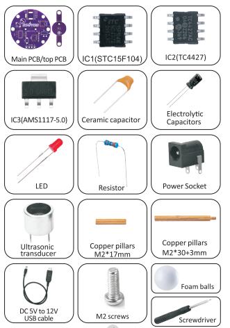
Supplies
Buy from USA Buy from UK Buy from DE Buy from IT Buy from FR Buy from ES ここでご購入を! ![]()
![]()
![]()
![]()
![]()
![]()
![]()
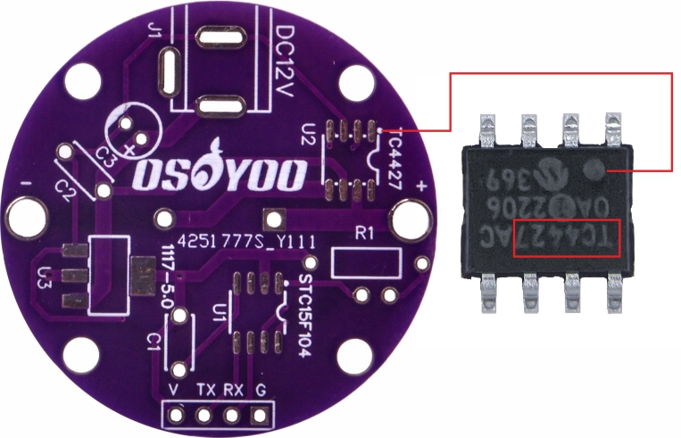
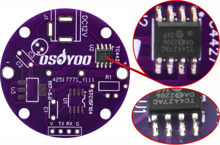
Step 1: Mount TC IC( TC4427) on U2
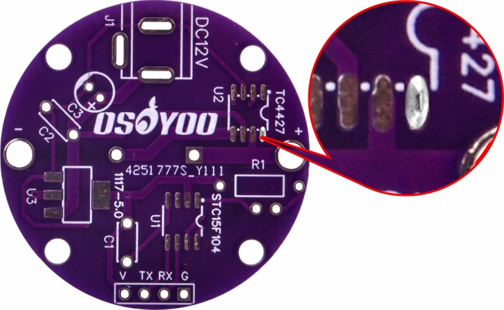
1.1)Be sure that the notch on the IC is in the same direction as the marking on the PC board.(Ps:Be extremely careful in the orientation of the IC.)
1.2)Select a solder pad on the PCB,then put solder on the pads.
1.3)Use a tweezer to put the IC(TC4427) on it, and hold in place. Then touch the soldering iron to one leg of the IC and let it melt the solder and get attached.
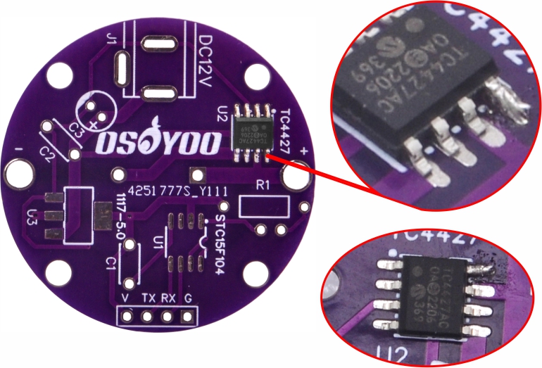 1.4)Solder the rest legs of the IC(TC4427).
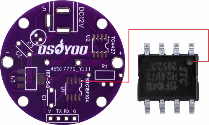
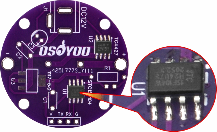
Step 2: Mount STC IC( STC15F) on U1 Using the Same Method .
Be sure that the dot on the IC is in the same direction as the marking on the PC board.
Step 3: Mount IC( AMS1117) on U3 Using the Same Method .

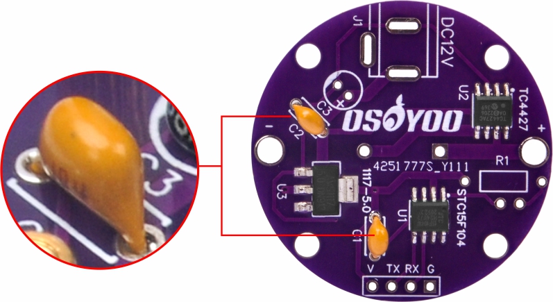
Step 4: Mount 2pcs 100nF Ceramic Capacitors on C1 and C2.
Solder and cut off the excess leads.
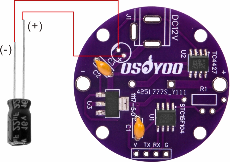
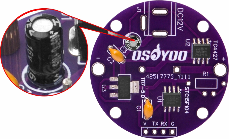
Step 5: Mount a 100UF Electrolytic Capacitor on C3.
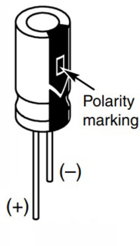
(Ps:Electrolytic capacitors have a positive and a negative electrode.Be sure to mount the Positive (+) of electrolytic capacitor to the hole marked(+) on the PC board.)
Warning: If the capacitor is connected with incorrect polarity,it may heat upand either leakor cause thecapacitor to explode.
Solder and cut off the excess leads.
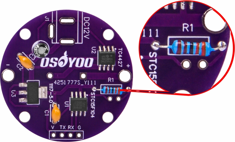
Step 6: Mount a Resistor on R1.
Solder and cut off the excess leads.
Step 7: Mount Power Socket on J1 and Solder .

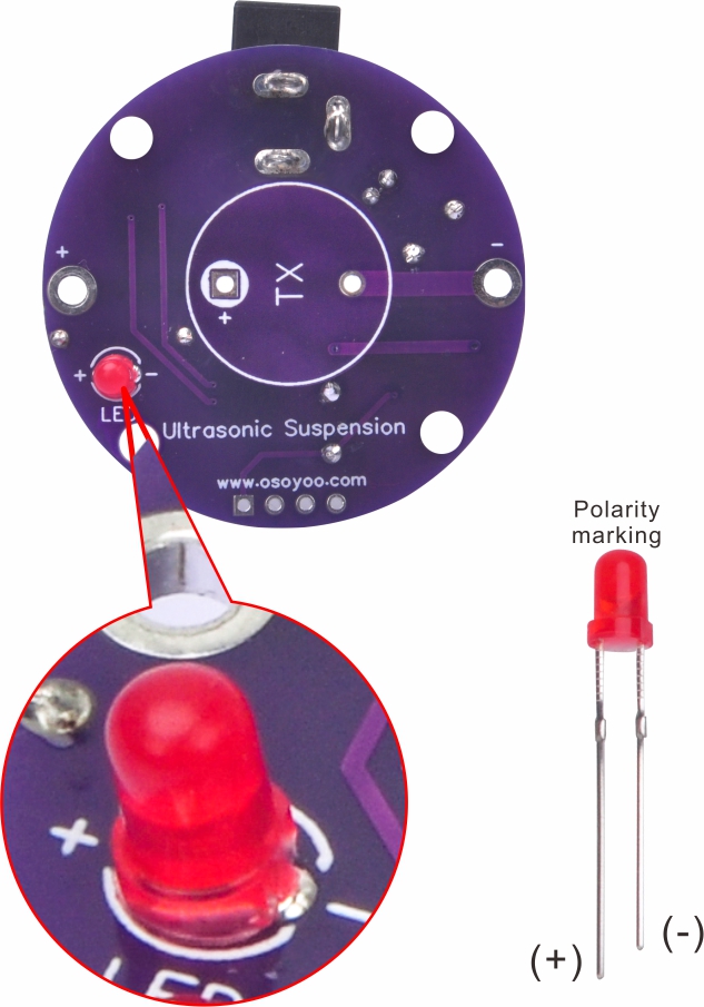
Step 8: Mount a Red LED on the Other Side of PCB.
(Ps:LED have polarity.Be sure to mount the Positive (+) of LED to the hole marked(+) on the PC board.)
Solder and cut off the excess leads.
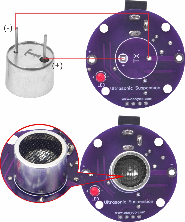
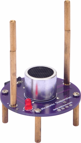
Step 9: Mount a Ultrasonic Transducer on PCB.
Ps:Ultrasonic transducer has two pins. One has a black circle around it, that' the positive (+) leg,put that in the hole marked (+) on the PC board.
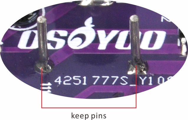
Solder and keep the metal pins.
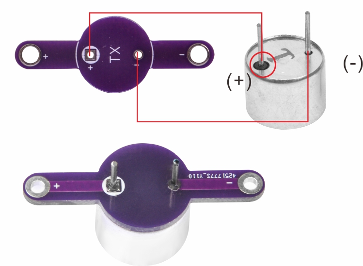
Step 10: Mount the Other Ultrasonic Transducer on Top PCB.
Solder and keep the metal pins.
Step 11: Fix M2*17MM Copper Pillar on the Main PCB by M2 Screws.

Step 12: Splices M2*17mm Copper Pillar and M2*30+3mm Copper Pillar Screw to a Whole Copper Pillar.

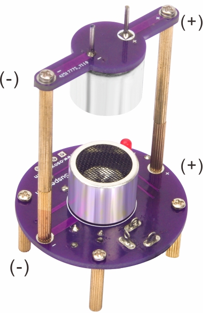
Step 13: Fix Top PCB on Main PCB With 2PCS Pillar From Last Step and 4pcs M2 Screws
(Note that the positive electrodes of the two PCB correspond to each other.)
Step 14: Operation:

After completing the assembly of the kit, double back to see that the soldering looks good and all of the components are in their proper place.If everything is all right power it via USB cable, LED willlight on. Use the tweezer to place the included foam balls into place.
Have fun and enjoy the science and technology---to levitate the foam ball.
Note: The USB cable in the package can boost the 5V voltage to 12V, and can be directly connected to the computer USB port to power the product.
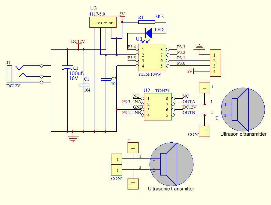
Step 15: Appendix
Schematic Diagram:
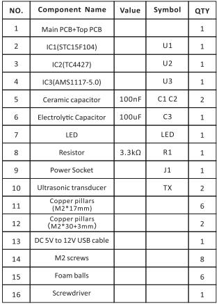
Component list:


![Tim's Mechanical Spider Leg [LU9685-20CU]](https://content.instructables.com/FFB/5R4I/LVKZ6G6R/FFB5R4ILVKZ6G6R.png?auto=webp&crop=1.2%3A1&frame=1&width=306)


